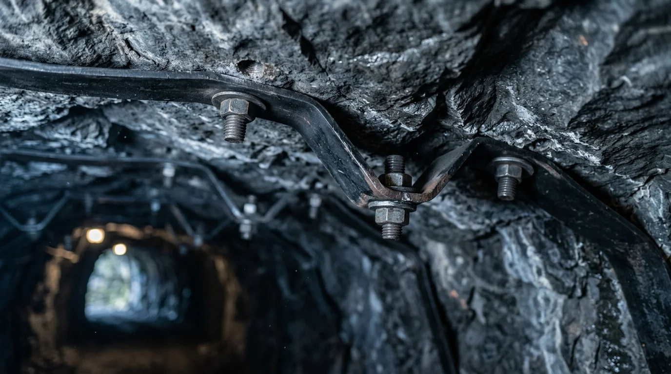
W-Strap Mechanism in Rockbolt Support
In a coal mine roadway, the W-strap (rockbolt support design) (also known as W-shaped steel strap or corrugated steel strap) performs three core functions:
Load Transfer: It distributes the concentrated load of a single bolt over a larger area of the surrounding rock surface, reducing local stress concentration. Field measurements show that after installing a W-strap, the uniformity of stress distribution on the surrounding rock surface improves significantly.
Integral Restraint: It connects multiple bolts into a mesh structure, forming a “beam-arch” composite support system. When a single bolt fails, the load can be transferred to adjacent bolts via the strap, preventing the expansion of local roof falls.
Delamination Suppression: The stiffness of the W-strap can suppress delamination deformation between the surface surrounding rock and deep surrounding rock. This effect is particularly critical for layered rock masses (e.g., interbedded shale and sandstone).
By the end you will know how to determine bolt row/column spacing and select the appropriate W-strap specification, and be able to design a rockbolt support system for a mine roadway.
Principles for Determining Bolt Row/Column Spacing
Bolt row/column spacing is not set arbitrarily; it must be calculated based on factors such as surrounding rock properties, roadway cross-section, and burial depth. Two common calculation methods are used:
Method 1: Empirical Formula Method
For moderately stable surrounding rock (Protodyakonov coefficient f=4-6), bolt spacing a = (0.6-0.8) × L, where L is the effective bolt length (m). For example, if the bolt length is 2.4m and the effective length is 2.0m, then spacing a = 1.2-1.6m, typically taken as 1.4m.
Method 2: Suspension Theory Method
Treating the unstable rock layer as a suspended load, bolt spacing a = √(P / (γ × h × K)), where P is the design bearing capacity of a single bolt (kN), γ is the rock unit weight (kN/m³), h is the thickness of the unstable rock layer (m), and K is the safety factor (1.5-2.0).
| Surrounding Rock Category | Protodyakonov Coefficient f | Recommended Bolt Spacing | Recommended Row Spacing | Bolt Length |
|---|---|---|---|---|
| Stable Rock | 8-10 | 1.5-2.0m | 1.5-2.0m | 1.8-2.2m |
| Moderately Stable | 4-6 | 1.2-1.5m | 1.2-1.5m | 2.0-2.5m |
| Unstable Rock | 2-4 | 0.8-1.2m | 0.8-1.0m | 2.5-3.5m |
| Fractured Rock | <2 | 0.6-0.8m | 0.6-0.8m | 3.0-4.0m |
W-Strap Specification Selection
The core parameters of a W-strap include: steel grade, cross-sectional dimensions, wave height and pitch, and length. The selection steps are as follows:
Step 1: Determine Steel Grade
Commonly used Q235B or Q345B hot-rolled steel plates are cold-formed. For general roadways, Q235B is sufficient; for high-stress roadways (burial depth >500m or tectonic stress zones), Q345B is selected.
Step 2: Calculate Required Section Modulus
The W-strap can be considered a simply supported beam, with mid-span bending moment M = q × a² / 8, where q is the load per unit length (kN/m), and a is the bolt spacing (m). Required section modulus W_z = M / [σ], where [σ] is the allowable stress of the steel (160MPa for Q235, 210MPa for Q345).
Step 3: Select Standard Specification
Based on the calculated W_z, choose from standard products. Common W-strap specifications are as follows:
| Specification | Steel Plate Thickness | Width | Wave Height | Section Modulus | Applicable Bolt Spacing |
|---|---|---|---|---|---|
| W280-3.0 | 3.0mm | 280mm | 50mm | 12.5 cm³ | ≤1.2m |
| W280-4.0 | 4.0mm | 280mm | 50mm | 18.2 cm³ | 1.2-1.5m |
| W320-4.0 | 4.0mm | 320mm | 60mm | 24.8 cm³ | 1.5-1.8m |
| W320-5.0 | 5.0mm | 320mm | 60mm | 32.5 cm³ | 1.8-2.0m |
Simplified Selection Table: For most coal mine roadways, the following empirical matching can be used:
- Bolt spacing 1.0-1.2m → W280-3.0 or W280-4.0
- Bolt spacing 1.2-1.5m → W280-4.0 or W320-4.0
- Bolt spacing 1.5-2.0m → W320-4.0 or W320-5.0
Case Study: Optimization of a Coal Mine Roadway Support
Background: A coal mine return airway had a burial depth of 450m, with surrounding rock of interbedded sandstone and shale (Protodyakonov coefficient f=3-4). The original design had a bolt spacing of 1.8m and row spacing of 1.8m, equipped with W280-3.0 straps. After 3 months of operation, roof sag reached 200mm, sidewall bulging reached 150mm, and some bolt plates were crushed.
Problem Analysis: ① The bolt spacing of 1.8m was too large, exceeding the reasonable span of the W280-3.0 strap; ② The strap’s section modulus was insufficient, causing plastic deformation under surrounding rock pressure; ③ The row spacing equaled the bolt spacing, failing to form an effective mesh restraint.
Optimization: ① Bolt spacing reduced to 1.2m, row spacing to 1.0m; ② Strap upgraded to W320-4.0; ③ Bolt length increased from 2.2m to 2.8m, anchoring into stable rock. After optimization, roof sag was controlled within 50mm, and sidewall deformation within 30mm, meeting requirements.
Construction Quality Control
Installation Requirements:
- The W-strap must be in close contact with the rock surface; gaps should be filled with wooden wedges or mortar to ensure uniform load transfer.
- Strap overlap length should be no less than 100mm, connected with at least two M16 bolts.
- The bolt plate must be placed on the wave crest of the W-strap, not in the wave trough (the trough has lower stiffness).
- The strap should be laid straight, with deflection not exceeding L/500 (L is the strap length).
Quality Inspection:
- Set up three measuring points every 100m of roadway to measure roof sag and sidewall convergence.
- Check the W-strap for obvious deformation, cracks, or corrosion.
- Use a torque wrench to check bolt preload, which should reach more than 90% of the design value.
- Monitor deformation data weekly during the first 3 months.
Summary
For high-frequency vibration conditions, wedge washers are preferred; spring washers are almost ineffective in Junker tests. For bolt spacing selection, the empirical formula method and suspension theory method provide a reliable basis, but the final design must be verified by field monitoring.
Next Steps
To obtain a W-strap and bolt spacing design suitable for your project, please prepare the following parameters:
- Protodyakonov coefficient (f) and rock type (e.g., shale, sandstone)
- Roadway cross-section dimensions (width, height) and burial depth
- Bolt design bearing capacity (kN) and length (m)
- Any specific standard requirements (e.g., GB 50086-2015)
Contact Yaxiio for technical support and quotation: Submit requirements.
Deep Reading
More systematic selection, procurement, or inspection guides.
- Corrosion-Resistant Fastener Selection for Municipal Water Treatment Plantswhitepaper
A more systematic guide on a related selection or inspection topic.
- Bolted Connection Engineering for Agricultural Facilities: Failure Mechanisms, Selection, and Maintenancewhitepaper
A more systematic guide on a related selection or inspection topic.
- Energy Storage System Busbar Bolt Torque and Contact Resistance Controlwhitepaper
A more systematic guide on a related selection or inspection topic.
This article helps with selection and application. But in real projects, specifying the right part is only step one, finding the right factory, controlling quality, and delivering on time is the real challenge. We cover fasteners, rubber, plastics, and industrial textiles across four categories, from Zhejiang industrial clusters to your project site, one team, end to end.
See Our Supply Chain Capabilities →