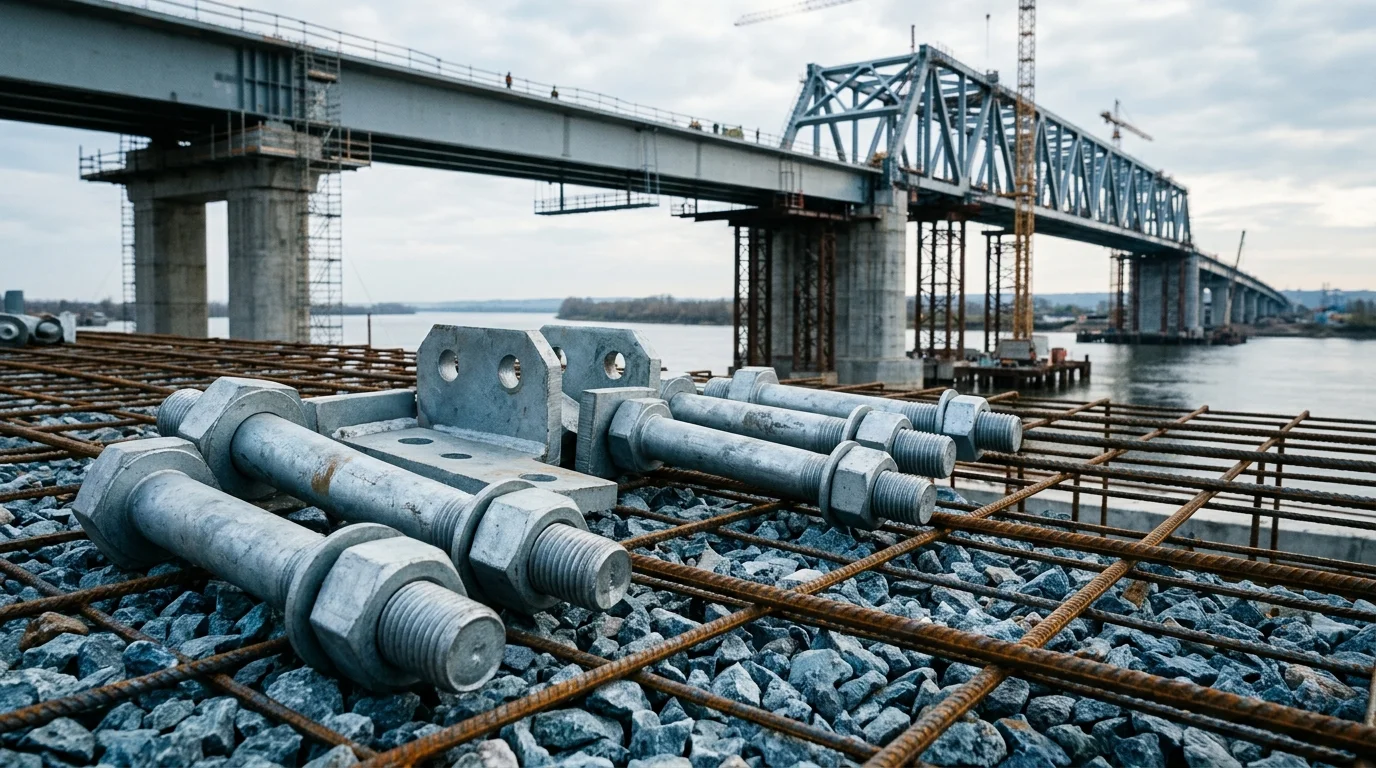
Mining Cable Support Hooks and Clamps
Cable hooks in mines should be treated as cable support and fixation hardware, not as simple hangers. Check the cable route, clamp structure, anchoring method, flame-retardant or anti-static boundary, and maintenance access before choosing polymer, galvanized or stainless hardware.
RISK AUDIT // ENGINEERING DIAGNOSIS
Procurement Pitfall Guide
"Cable hooks fail when treated as simple hangers, not as support hardware."
QC-AUDIT // REV.5
SCALE 1:1 · 03 ITEMS
RISK-01
Cable Hook Detachment in Blasting Shockwave
Corrective Measures
RISK-02
High Temperature Environment Causes Plastic Hook Strength Degradation
Corrective Measures
RISK-03
Corrosive Gas Causes Metal Hook Rust and Fracture
Corrective Measures
FIELD-SPECIFIC INSIGHT
Treat cable hooks as a support system
For mining cable routing, the main question is not only hook material. Public mine-safety material frames high-voltage cable protection around guarding, support systems and reduced contact risk. That makes hooks, clamps, brackets and anchors part of one fixation package.
WHAT TO CHECK
- 1Start with the cable route: cables near travel ways, moving equipment or conveyors need a stronger support logic than temporary ties.
- 2Check the full support package: hook, clamp, bracket and anchor hardware should be specified together.
- 3Match material to environment: polymer, galvanized steel and stainless hardware carry different risks in humid, dusty or corrosive areas.
- 4Ask for flame-retardant, anti-static or project-specific safety evidence when the cable route is underground or safety-critical.
| Check | Why it matters | What to specify |
|---|---|---|
| Cable route | Travel ways and equipment zones increase sheath wear and contact risk | Gallery location, mounting height, conveyor or mobile-equipment proximity |
| Fixation package | A hook alone does not prove long-term reliability; loose anchors or clamps can cause sagging | Hook, clamp, bracket, anchor bolt or expansion fastener combination |
| Flame and static boundary | Underground mining should not be treated like ordinary industrial cable routing | Flame-retardant, anti-static, non-metallic guarding or project-required safety evidence |
| Maintenance access | Hard-to-remove hooks delay cable replacement and fault response | Spacing, tool access, replacement method and spare-part rule |
Use this page as a procurement boundary. Final load, spacing and fire-performance requirements must be verified against the project specification and supplier test reports.
Evidence level: standard-backed
INDUSTRY TECH REFERENCE
Three Numbers on the Underground Corrosion Environment Before Choosing Hook Material
Hooks and clamps sit on roadway walls in the same water that fills the workings — the acidity of mine water and the strength loss it drives are the first basis for material selection in wet roadways.
| Dimension | Measured / basis | What it means for cable fixing hardware |
|---|---|---|
| Acidity of mine water | Acidic sulfate water measured at pH 3.4–4.3 (Australian coal mines) | Corrosion accelerates sharply below pH 5 — treat a wet roadway as a corrosive medium, not an atmospheric environment |
| Strength-loss rate | 3.5 years in this water: rock-bolt tensile strength down 31–39% | Metal fixings in the same water lose strength at the same order of magnitude (magnitude estimate) — size hook wall reserve against the corroded state |
| Section loss | Same run measured about 11.7% diameter loss | Hooks and clamps are small-section parts; the same percentage loss leaves less usable reserve — which is exactly why section checks matter |
| Brittle-fracture risk in high-strength steel | High-strength steel + tension + corrosive media → brittle fracture with no visible plastic warning | For high-strength rods and bolts underground, choose corrosion-resistant material plus a coating system instead of quoting a strength grade alone |
pH 3.4–4.3, 3.5 years, −31~39% and −11.7% are measured values on X-grade rock bolts from Australian coal mines (Aziz et al. 2014, traced); "same order of magnitude for hooks" is a magnitude estimate extended from the same mine-water medium, with no same-source measurement on hooks or clamps; the SCC row is an extension to high-strength steel fasteners.
INDUSTRY TECH REFERENCE
How Acidic Mine Water Thins a Hook Year by Year, Until It Breaks
Take metal hooks and clamps in a wet roadway. Corrosion is a slow variable: the surface looks unchanged while section and strength keep dropping year by year, with almost no warning before fracture.
- 1Mine water is acidic sulfate, measured at pH 3.4–4.3 — hooks sit in a corrosive medium below pH 5 for their whole service life
- 2Loss is uniform: the same environment measured about 11.7% diameter loss over 3.5 years, and the smaller the section, the faster the reserve disappears (magnitude estimate)
- 3Tensile strength drops 31–39% over the same period — the cable load stays constant, so the stress ratio climbs year by year
- 4Underground fixings have no routine-recheck culture (bolts go into the roof for life); with hook checks scheduled by the year, fracture gives almost no early warning
- 5One broken hook drops the cable to the floor — a contact hazard for plant and people — and a slow variable ends in a roadway-level outage or injury
pH, −31~39% and −11.7% are measured on X-grade rock bolts (traced) and extended to hooks; "smaller section loses reserve faster" is general section logic, not measured; step 5 is a qualitative consequence of the scenario (cable fall, outage, contact hazard), with no figures.
INDUSTRY TECH REFERENCE
Cable Fixing Hardware Incoming and Acceptance: Three Gates First
Underground buying is not catalog selection — the three gates of certification, documentation and acceptance cadence decide whether this batch of hooks serves safely in the roadway.
- Certification gate (China): the MA mine-safety mark is a one-vote veto — products on the catalog cannot be made or sold without it and mines cannot buy them; check before ordering whether hooks, clamps or anchor bolts are on the MA catalog and whether certification applies (a catalog item already confirmed: resin bolt cartridges)
- Documentation is part of the delivery (US practice): MSHA has mines request manufacturer certification for roof bolts and accessories — ship the certification and material certificates with the batch as part of the order
- Acceptance is the final inspection: sampling of underground fixings happens on the installation shift, with no after-sales recheck stage — the dispute window is very short, so batch-to-batch consistency matters more than unit price
- Select material for the whole service life: support is designed as "not touched for ten years", and the corrosion rate sets the real upper life limit — spec hook material and coating against the full roadway life, not against piece price
The MA scheme and the resin-cartridge catalog example come from the MA national center (medium-high confidence); the MSHA manufacturer-certification practice comes from 30 CFR §56.3203 / §57.3203 (traced); "not touched for ten years" follows the KB's statement of support-design intent. No bolt-specific torque/tension figures (the 50% rule, 150 ft-lb, etc.) are used here — those belong to sibling pages.
INDUSTRY TECH REFERENCE
Cable-Hanging and Ground-Support Lines: Draw the Buying Boundary First
Draw the boundary before ordering: cable-hanging hardware and anchors sit on the fastener supply line; bolt bodies, resin and drilling machines do not.
In scope (fastener-class hardware): cable hooks, cable clamps and fixing clamps with their anchor bolts (expansion/anchor type), plus ground-support fittings from the same roadway — rock bolt nuts with plates (including spherical seat washers), W-strap connection bolts, cable bolt locks (wedges/anchor bodies) and mesh tie wire. Out of scope (dedicated lines and chemicals): bolt and cable bodies (left-hand rebar and prestressing strand on dedicated production lines), resin cartridges (chemicals), and roof bolter machines. Quote against this boundary so dedicated bolt bodies are not asked for as ordinary fasteners. Cable-hanging hardware itself is not on the profile's in-scope list; whether it joins this product line is for the merge review to decide.
The in-scope/out-of-scope lists are drawn from the boundary row of KB §5 (traced); cable-hanging hardware itself is not in that in-scope column — a draft-stage gap, left for the merge review to decide whether the supply line extends to hanging hardware.
PLAN COMPARISON
Three-Plan Core Parameter Comparison
Compare row by row. Click column headers to jump to plan details.
| A · Plan A · PA66 Plastic Standard Hook | B · Plan B · 304 Stainless Steel Heavy-Duty Hook | C · Plan C · Q235B Extreme Heavy-Duty Hook | |
|---|---|---|---|
| 1. SINGLE PLASTIC HOOK | |||
| SPEC | Load capacity 50kg, PA66+GF30 flame retardant V-0 grade | Load capacity 100kg, 304 precision casting + polishing | Load capacity 200kg, Q235B forged + hot-dip galvanized |
| MATERIAL | PA66 | 304 | Q235B |
| GRADE | Flame retardant V-0 | — | — |
| FINISH | HDG >=55um per ISO 1461 | HDG >=55um per ISO 1461 | HDG >=55um per ISO 1461 |
| 2. MULTI-COMBINATION HOOK | |||
| SPEC | 2-5 units integrated molding, spacing 150mm | M10-M16, A2-70 stainless steel + Nordlock washer | Al2O3 ceramic, withstand voltage 35kV, anti-arc |
| MATERIAL | — | 70 stainless steel | — |
| GRADE | — | A2-70 | — |
| FINISH | HDG >=55um per ISO 1461 | HDG >=55um per ISO 1461 | HDG >=55um per ISO 1461 |
| 3. EXPANSION BOLT | |||
| SPEC | M8×40, nylon expansion tube + galvanized screw | EPDM weather-resistant rubber, thickness 3mm, prevents cable wear | M16-M20, grade 8.8 Dacromet coating |
| MATERIAL | Nylon | EPDM | — |
| GRADE | — | — | Grade 8.8 |
| FINISH | HDG >=55um per ISO 1461 | HDG >=55um per ISO 1461 | HDG >=55um per ISO 1461 |
| 4. ANTI-SLIP RUBBER PAD | |||
| SPEC | EPDM rubber lining, prevents cable wear | Copper tinned, cross-section ≥25mm², reliable grounding | RFID chip, records installation time and inspection records |
| MATERIAL | EPDM | — | EPDM Rubber |
| FINISH | HDG >=55um per ISO 1461 | HDG >=55um per ISO 1461 | HDG >=55um per ISO 1461 |
| 5. IDENTIFICATION PLATE | |||
| SPEC | PVC material, marks circuit number | Epoxy zinc-rich primer, salt spray resistance 500h | Hydraulic torque wrench, preload controllable ±5% |
| MATERIAL | PVC | — | — |
| FINISH | HDG >=55um per ISO 1461 | HDG >=55um per ISO 1461 | HDG >=55um per ISO 1461 |
SELECTION GUIDE
How to Choose a Hook Solution Based on Cable Type?
| Operating condition | Recommended option | Key basis |
|---|---|---|
| Communication/control lines, dry roadways | Plan A · PA66 Plastic Standard Hook (lowest cost, easy installation) | PA66+GF30 flame retardant V-0 grade; load capacity ≥50kg for φ20-40mm small section cables |
| Power cables / wet corrosive environment | Plan B · 304 Stainless Steel Heavy-Duty Hook (corrosion resistant, long life) | 304 stainless steel; load capacity ≥100kg for φ40-80mm large section power cables |
| High voltage cables / deep high ground pressure | Plan C · Q235B Extreme Heavy-Duty Hook (safe, reliable) | Q235B forged + hot-dip galvanized; load capacity ≥200kg; ceramic insulation liner withstands 35kV for 10kV+ cables |
Plan A · PA66 Plastic Standard Hook
C3 standard per ISO 12944-2 for dry roadways
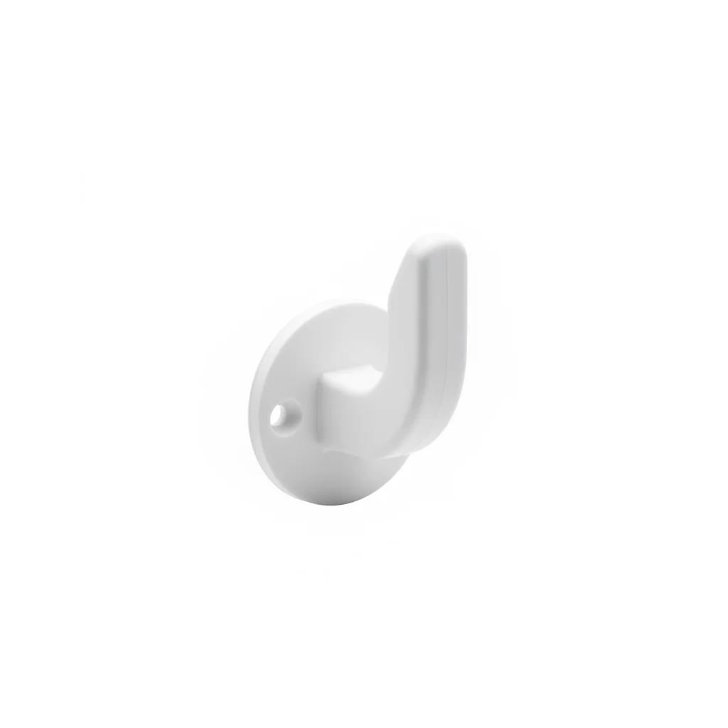
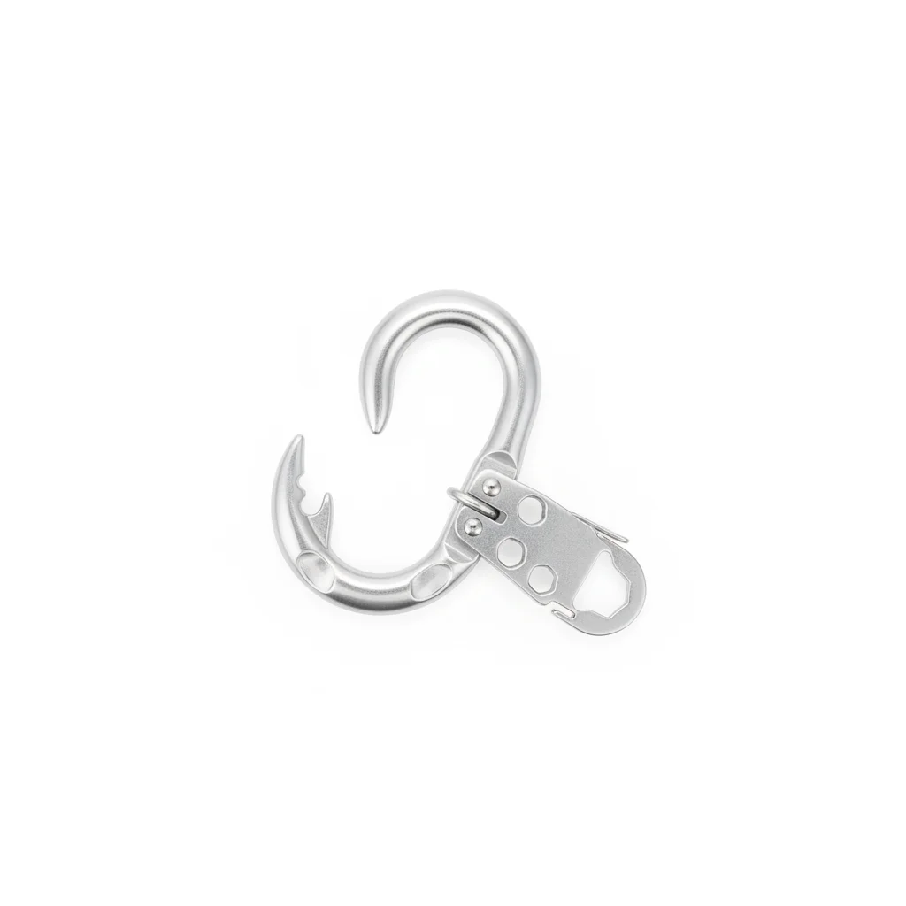
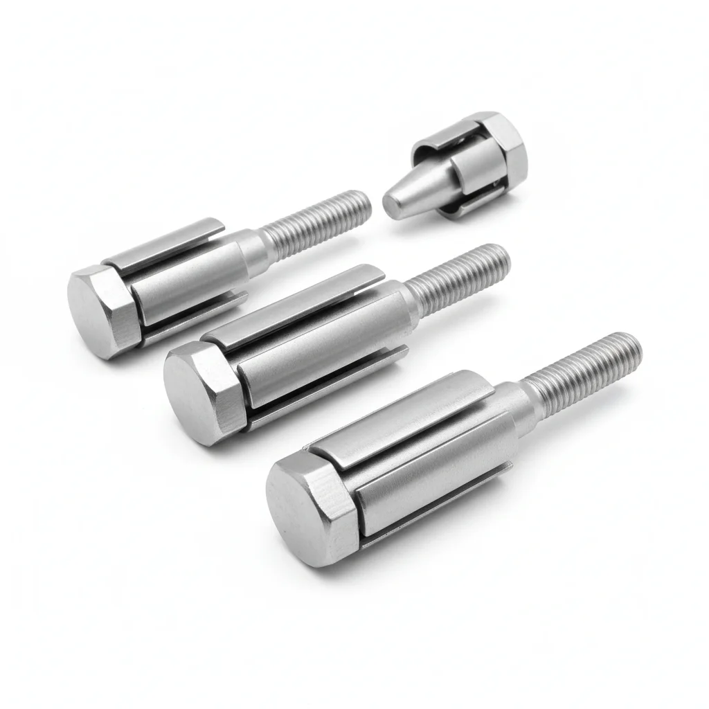
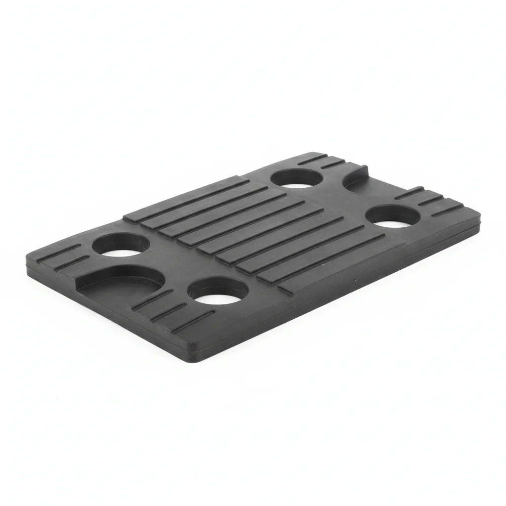
| Single Plastic Hook | Multi-Combination Hook | Expansion Bolt | Anti-Slip Rubber Pad | Identification Plate | |
|---|---|---|---|---|---|
| SPEC | Load capacity 50kg, PA66+GF30 flame retardant V-0 grade | 2-5 units integrated molding, spacing 150mm | M8×40, nylon expansion tube + galvanized screw | EPDM rubber lining, prevents cable wear | PVC material, marks circuit number |
| MATERIAL | PA66 | — | Nylon | EPDM | PVC |
| GRADE | Flame retardant V-0 | — | — | — | — |
| FINISH | HDG >=55um per ISO 1461 | HDG >=55um per ISO 1461 | HDG >=55um per ISO 1461 | HDG >=55um per ISO 1461 | HDG >=55um per ISO 1461 |
| CORROSION | C3 (ISO 12944-2) | C3 (ISO 12944-2) | C3 (ISO 12944-2) | C3 (ISO 12944-2) | C3 (ISO 12944-2) |
| TEMP | -20°C to +80°C | -20°C to +80°C | -20°C to +80°C | -20°C to +80°C | -20°C to +80°C |
| WEIGHT | ~0.5 kg/piece | ~0.5 kg/piece | ~0.5 kg/piece | ~0.5 kg/piece | ~0.5 kg/piece |
| MOQ | 100 pcs | 100 pcs | 100 pcs | 100 pcs | 100 pcs |
| PACK | VCI paper + carton | VCI paper + carton | VCI paper + carton | VCI paper + carton | VCI paper + carton |
| STD | ISO 898-1, GB/T 3098.1 | ISO 898-1, GB/T 3098.1 | ISO 898-1, GB/T 3098.1 | ISO 898-1, GB/T 3098.1 | ISO 898-1, GB/T 3098.1 |
| USE | PA66+GF30 flame retardant V-0 grade | Spacing 150mm | Nylon expansion tube + galvanized screw | Prevents cable wear | Marks circuit number |
PROCEDURE
- Drill holes at marked positions, ensuring spacing ≤1.5m, and clean out dust.
- Insert the M8×40 nylon expansion bolt into the hole and tap flush with the wall.
- Slide the PA66+GF30 hook onto the expansion bolt and hand-tighten the galvanized screw.
- Use a torque wrench to tighten the screw to the recommended torque for M8 expansion bolts.
- Verify the hook is level and firmly seated; attach the identification plate to mark the circuit number.
COMMON ERRORS
| ✕ WRONG | CONSEQUENCE | ✓ CORRECT |
|---|---|---|
| Using ordinary PA66 hooks without glass fiber reinforcement | Hook deforms or breaks under blasting shockwave, causing cable fall within months. | Choose PA66+GF30 hooks with flame retardant V-0 grade for higher impact strength. |
| Overtightening the expansion bolt, crushing the nylon tube | Loss of anchoring force, hook works loose under vibration. | Tighten to the specified torque for M8 expansion bolts, not beyond. |
MAINTENANCE
Inspect hooks every shift for looseness or deformation, especially after blasting. Replace any hook with visible cracks or deformation. Re-torque loose expansion bolts immediately. In high ground pressure areas, check more frequently.
Plan B · 304 Stainless Steel Heavy-Duty Hook
C4 Harsh per ISO 12944-2
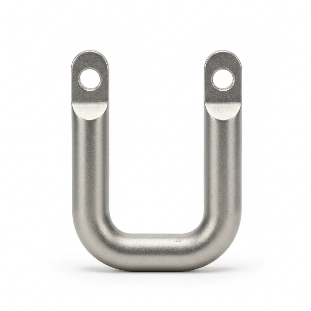
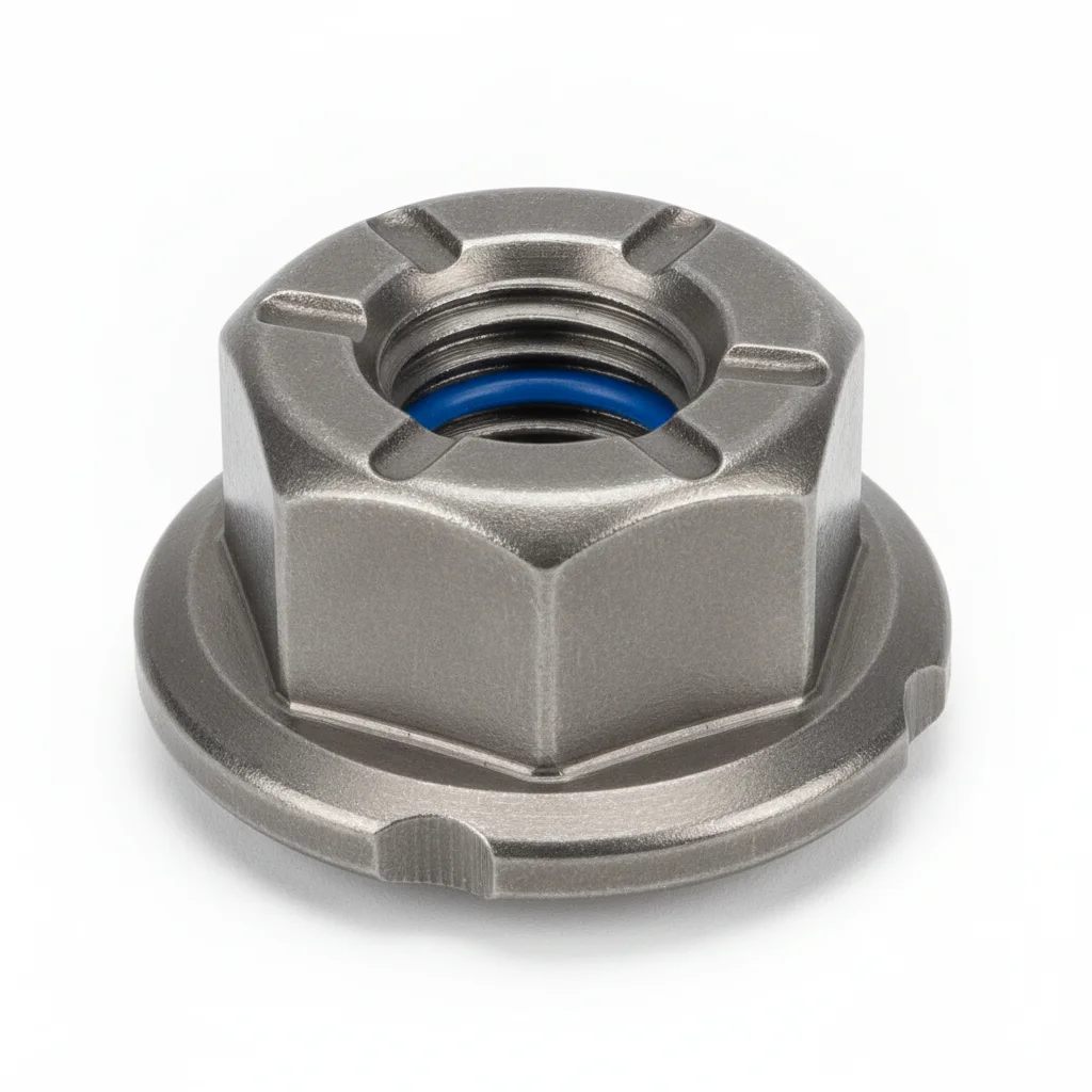
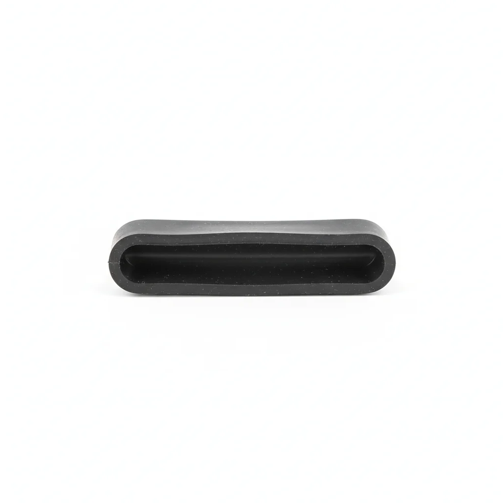
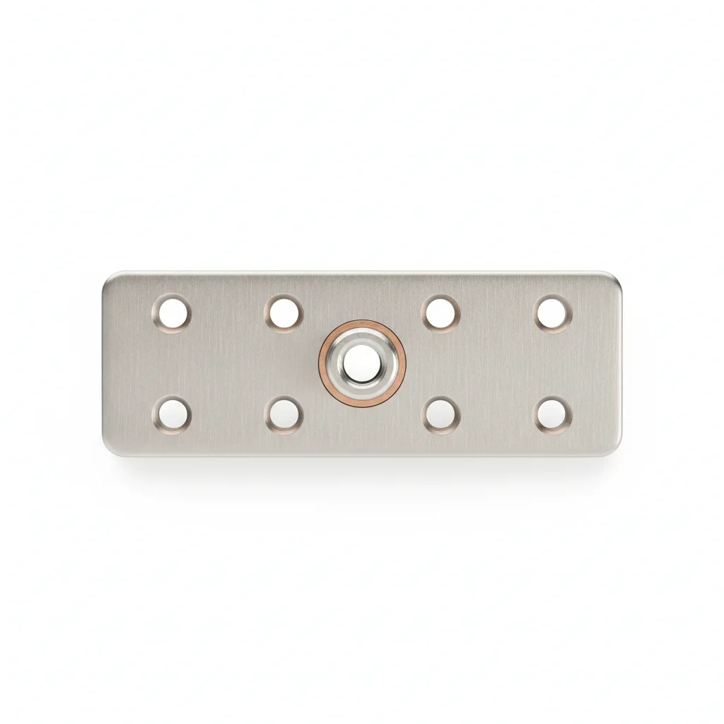
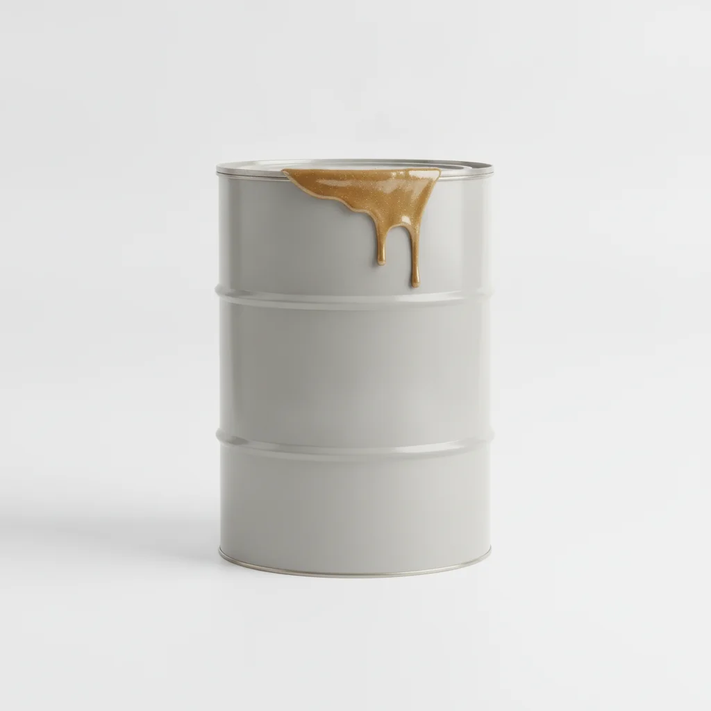
| U-Hook | Anti-Loosening Lock Nut | Rubber Sleeve | Grounding Connector Plate | Anti-Corrosion Coating | |
|---|---|---|---|---|---|
| SPEC | Load capacity 100kg, 304 precision casting + polishing | M10-M16, A2-70 stainless steel + Nordlock washer | EPDM weather-resistant rubber, thickness 3mm, prevents cable wear | Copper tinned, cross-section ≥25mm², reliable grounding | Epoxy zinc-rich primer, salt spray resistance 500h |
| MATERIAL | 304 | 70 stainless steel | EPDM | — | — |
| GRADE | — | A2-70 | — | — | — |
| FINISH | HDG >=55um per ISO 1461 | HDG >=55um per ISO 1461 | HDG >=55um per ISO 1461 | HDG >=55um per ISO 1461 | HDG >=55um per ISO 1461 |
| CORROSION | C3 (ISO 12944-2) | C3 (ISO 12944-2) | C3 (ISO 12944-2) | C3 (ISO 12944-2) | C3 (ISO 12944-2) |
| TEMP | -20°C to +80°C | -20°C to +80°C | -20°C to +80°C | -20°C to +80°C | -20°C to +80°C |
| WEIGHT | ~0.5 kg/piece | ~0.5 kg/piece | ~0.5 kg/piece | ~0.5 kg/piece | ~0.5 kg/piece |
| MOQ | 100 pcs | 100 pcs | 100 pcs | 100 pcs | 100 pcs |
| PACK | VCI paper + carton | VCI paper + carton | VCI paper + carton | VCI paper + carton | VCI paper + carton |
| STD | ISO 898-1, GB/T 3098.1 | ISO 898-1, GB/T 3098.1 | ISO 898-1, GB/T 3098.1 | ISO 898-1, GB/T 3098.1 | ISO 898-1, GB/T 3098.1 |
| USE | 304 precision casting + polishing | A2-70 stainless steel + Nordlock washer | Prevents cable wear | Reliable grounding | Salt spray resistance 500h |
PROCEDURE
- Degrease the 304 U-Hook and M10-M16 A2-70 lock nut surfaces with acetone to remove any oily film from the wet corrosive environment.
- Slide the 3mm EPDM rubber sleeve over the cable before seating it in the U-Hook to prevent sheath wear.
- Position the U-Hook against the roadway wall, insert the A2-70 lock nut with Nordlock washer, and tighten in a cross-pattern to the specified torque.
- Attach the copper tinned grounding connector plate (cross-section ≥25mm²) to the hook assembly to ensure reliable grounding.
- Apply the epoxy zinc-rich anti-corrosion coating (salt spray resistance 500h) to all exposed threads and contact points.
- Verify hook alignment and cable clearance, ensuring the rubber sleeve fully covers the contact area without gaps.
COMMON ERRORS
| ✕ WRONG | CONSEQUENCE | ✓ CORRECT |
|---|---|---|
| Using a plain carbon steel U-bolt instead of the 304 stainless steel precision casting in a wet, corrosive roadway. | Rust forms within months, pitting depth can reach 0.5mm, and load capacity drops by 40%, leading to cable detachment. | Confirm the U-Hook is 304 precision casting and use the A2-70 stainless lock nut with Nordlock washer to resist loosening. |
| Omitting the EPDM rubber sleeve between the cable and the hook in a vibrating or abrasive environment. | The cable sheath wears through, exposing conductors and creating a shock or fire hazard. | Always fit the 3mm EPDM sleeve over the cable before seating it in the hook to prevent wear. |
MAINTENANCE
Inspect each shift for signs of corrosion or loosening; re-torque any hook that has lost more than 80% of specified torque. Annually, check the grounding connector plate for continuity and the rubber sleeve for cracks or hardening. Replace any 304 component showing pitting deeper than 0.3mm or corrosion covering more than 5% of the surface.
Plan C · Q235B Extreme Heavy-Duty Hook
C5-M Extreme per ISO 12944-2
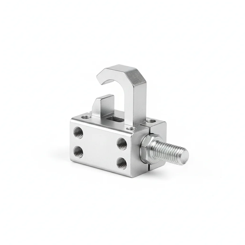
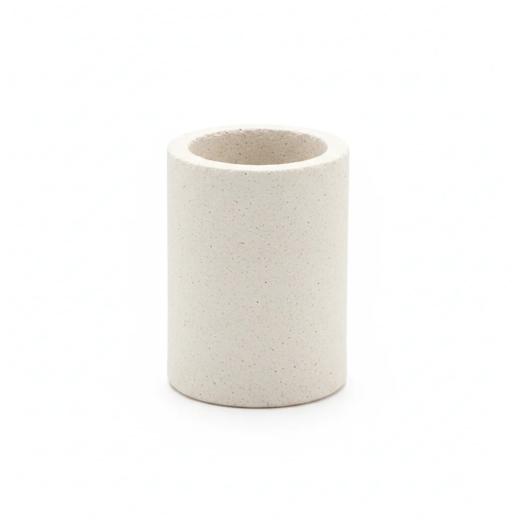
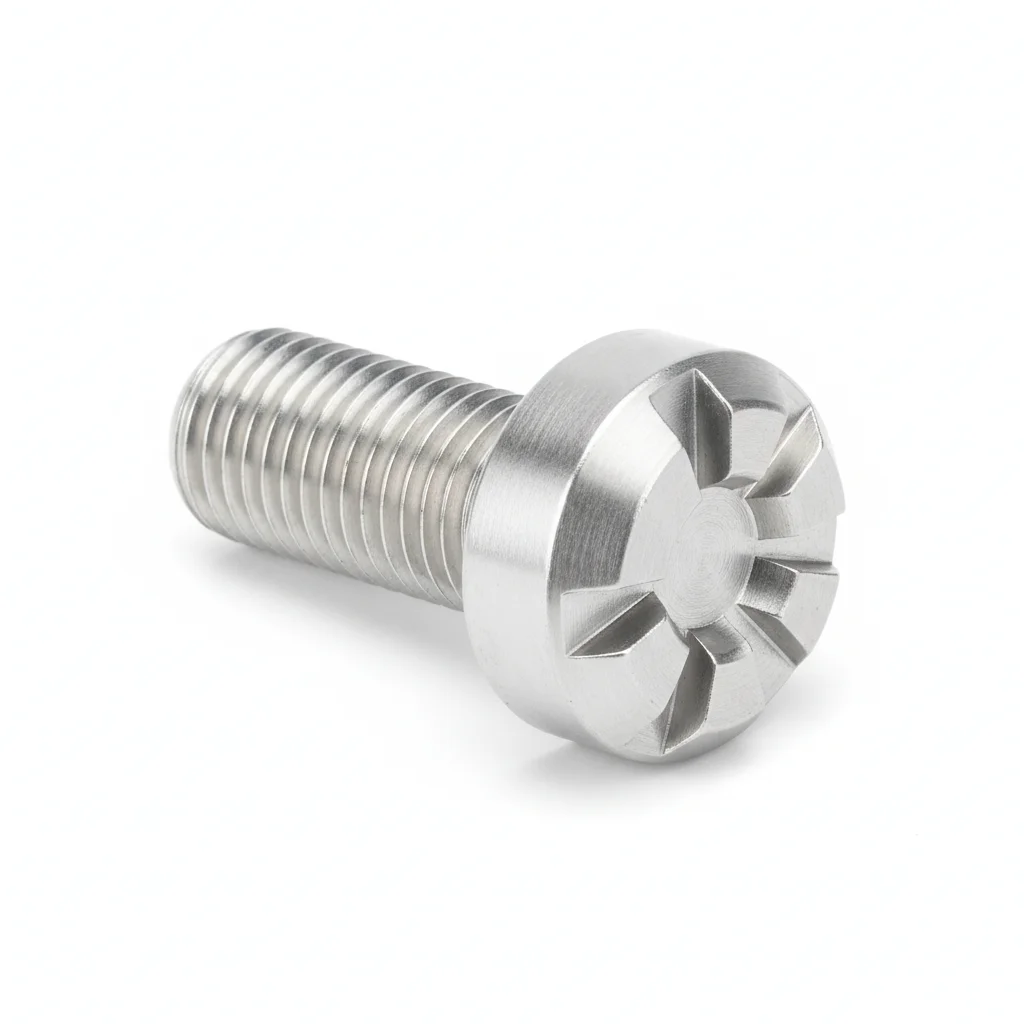
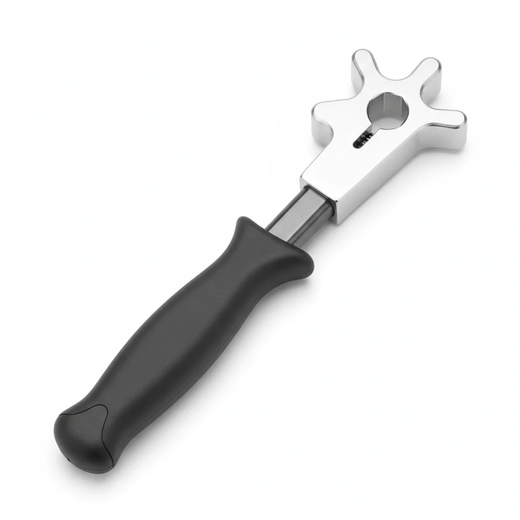
| Reinforced Metal Hook | Ceramic Insulation Liner | Special Alloy Bolt | Smart Monitoring Tag | Dedicated Installation Tool | |
|---|---|---|---|---|---|
| SPEC | Load capacity 200kg, Q235B forged + hot-dip galvanized | Al2O3 ceramic, withstand voltage 35kV, anti-arc | M16-M20, grade 8.8 Dacromet coating | RFID chip, records installation time and inspection records | Hydraulic torque wrench, preload controllable ±5% |
| MATERIAL | Q235B | — | — | EPDM Rubber | — |
| GRADE | — | — | Grade 8.8 | — | — |
| FINISH | HDG >=55um per ISO 1461 | HDG >=55um per ISO 1461 | HDG >=55um per ISO 1461 | HDG >=55um per ISO 1461 | HDG >=55um per ISO 1461 |
| CORROSION | C3 (ISO 12944-2) | C3 (ISO 12944-2) | C3 (ISO 12944-2) | Not applicable (polymer) | C3 (ISO 12944-2) |
| TEMP | -20°C to +80°C | -20°C to +80°C | -20°C to +80°C | -20°C to +80°C | -20°C to +80°C |
| WEIGHT | ~0.5 kg/piece | ~0.5 kg/piece | ~0.5 kg/piece | ~0.5 kg/piece | ~0.5 kg/piece |
| MOQ | 100 pcs | 100 pcs | 100 pcs | 100 pcs | 100 pcs |
| PACK | VCI paper + carton | VCI paper + carton | VCI paper + carton | VCI paper + carton | VCI paper + carton |
| STD | ISO 898-1, GB/T 3098.1 | ISO 898-1, GB/T 3098.1 | ISO 898-1, GB/T 3098.1 | ISO 898-1, GB/T 3098.1 | ISO 898-1, GB/T 3098.1 |
| USE | Q235B forged + hot-dip galvanized | Anti-arc | Grade 8.8 Dacromet coating | Records installation time and inspection records | Preload controllable ±5% |
PROCEDURE
- Clean the Q235B forged hook and M16-M20 grade 8.8 Dacromet bolts with MEK to remove all contaminants before assembly.
- Position the ceramic insulation liner (Al2O3, withstand voltage 35kV) inside the hook to isolate the high-voltage cable from the metal structure.
- Align the hook on the roadway support and insert the grade 8.8 bolts with Dacromet coating; use the hydraulic torque wrench to achieve preload within ±5%.
- Attach the smart monitoring tag (RFID) to the hook, recording installation date and torque data for future inspections.
- Verify that the ceramic liner fully covers the cable contact area and that no metal parts touch the cable directly.
- Conduct a final pull test to 80% of the 200kg rated load and document the results with the RFID tag.
COMMON ERRORS
| ✕ WRONG | CONSEQUENCE | ✓ CORRECT |
|---|---|---|
| Using ordinary galvanized bolts instead of the specified grade 8.8 Dacromet-coated alloy bolts in a high ground pressure area. | The bolts may not withstand the dynamic loads, leading to fatigue failure and cable detachment, risking arc flash or fire. | Use only the supplied M16-M20 grade 8.8 bolts with Dacromet coating and tighten with the hydraulic torque wrench to ±5% preload. |
| Skipping the ceramic insulation liner for a 10kV or higher cable. | Without the 35kV withstand voltage liner, the cable insulation can be compromised, leading to arcing and potential fire. | Always install the Al2O3 ceramic liner between the cable and the hook to maintain the required insulation level. |
MAINTENANCE
Perform a visual inspection each shift for signs of rock pressure damage or arcing. Use the RFID tag to track inspection history; at each overhaul window, verify torque with the hydraulic wrench and check the ceramic liner for cracks. Replace any component showing corrosion depth greater than 1mm or deformation exceeding 10% of original size.
REFERENCED STANDARDS
Technical Basis and Reference Standards
General Test Methods and Judgment Rules for Flame Retardant and Antistatic Safety Performance of Polymer Products for Coal Mines
Coal Mine Anchor Rod and CableSafety Marking for Mining Products
Non-Metallic Products for Underground Coal MinesPower Cables with Extruded Insulation for Rated Voltages from 1kV (Um=1.2kV) up to 35kV (Um=40.5kV) and Accessories
Plastic Burning BehaviorCable Hooks for Coal Mines
Mining Cable HookStandard Specification for Chromium and Chromium-Nickel Stainless Steel Plate, Sheet, and Strip (304 Material Standard)
SUPPLIER CAPABILITY
Quality, Delivery & Customization
Quality Control
- ✓MTC material certificates with every batch
- ✓Key parts sampled for hardness/salt spray/torque coefficient
- ✓100% inspection or AQL sampling before shipment
Delivery
- ✓Standard parts made to order: 7-15 days
- ✓Custom parts: 25-45 days
- ✓FOB/CIF/DDP supported
Customization
- ✓Drawing review and material matching
- ✓Non-standard sizes/heads/threads
- ✓Small-batch prototyping supported
Certification
- ✓Material certificates (MTC)
- ✓Spectrographic analysis reports
- ✓Salt spray test reports (on request)
MOQ: No MOQ for standard parts; custom parts assessed by process complexity
FAQ
Frequently Asked Questions
RELATED READING
Keep Reading & Next Step
BEYOND TECHNICAL SPECS
Finding the right factory, controlling quality, delivering on time — that's the real challenge. We cover fasteners, rubber, plastics, industrial textiles. One team, end to end.
SEE CAPABILITIES →