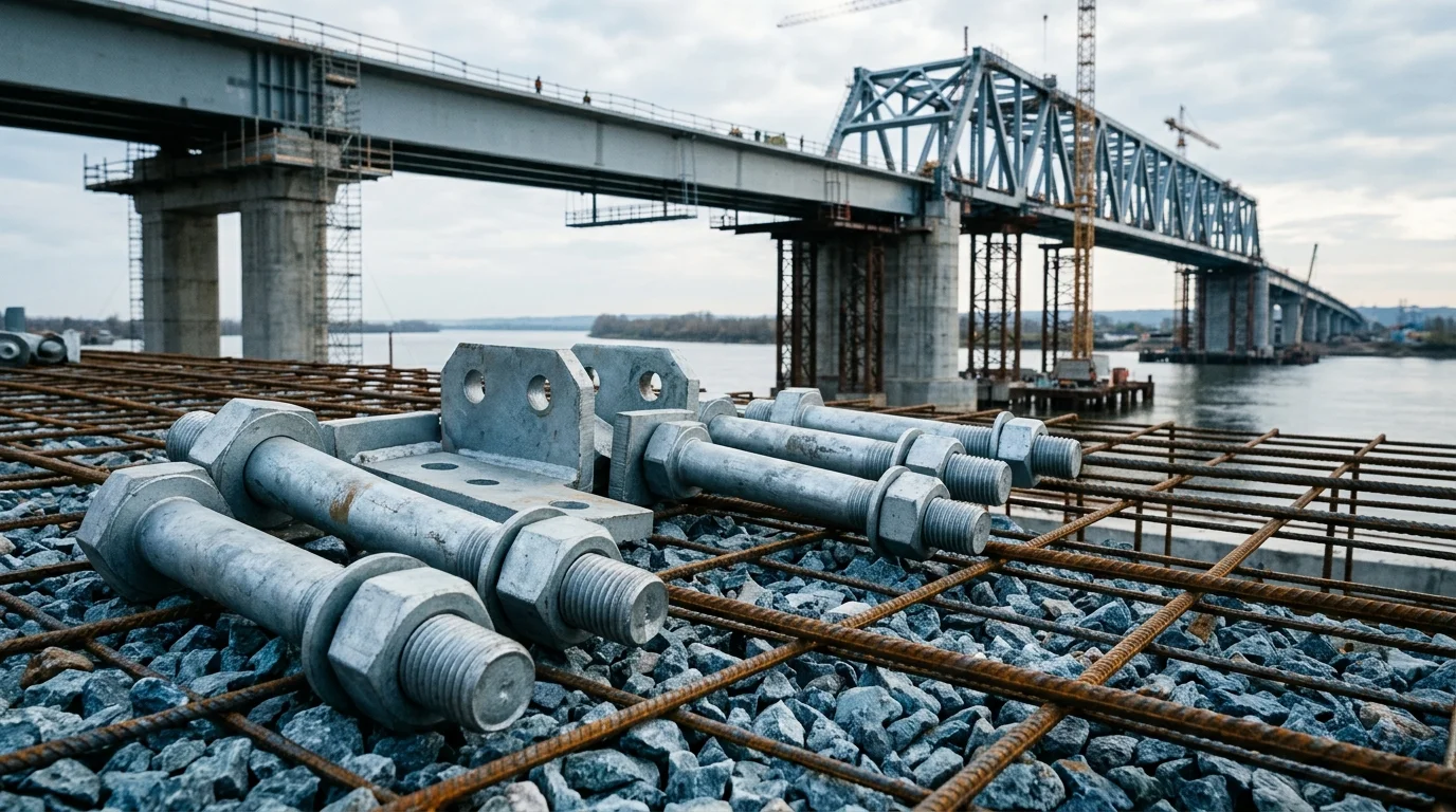
Impact Bed Fastener Comparison: NR vs PU vs Ceramic
For mining material handling drop zones, three impact bed solutions are available: Plan A (NR standard), Plan B (PU heavy-duty), and Plan C (ceramic extreme). Compare buffer bar materials, bolt grades, and corrosion protection to match your drop conditions and prevent belt damage
RISK AUDIT // ENGINEERING DIAGNOSIS
Procurement Pitfall Guide
"Impact bed failures often stem from fastener and bracket issues that are overlooked during procurement."
QC-AUDIT // REV.5
SCALE 1:1 · 03 ITEMS
RISK-01
Buffer bar bolts plastically deform and elongate under drop impact
Corrective Measures
RISK-02
Buffer bar rubber high-temperature aging and impact cracking
Corrective Measures
RISK-03
Bracket rust and fracture in acidic corrosive drop material
Corrective Measures
FIELD-SPECIFIC INSIGHT
Key Differences in Fastener and Bracket Selection for Impact Beds
While buffer bar material often gets attention, the fasteners and brackets are critical for impact bed reliability. Bolt plastic elongation, bracket corrosion, and coating selection directly affect belt tear prevention and maintenance intervals
WHAT TO CHECK
- 1Bolt grade: Plan A uses Grade 8.8 Dacromet; Plan B uses Grade 10.9 phosphated anti-seize; Plan C uses Inconel 625. Higher grade resists plastic elongation under impact
- 2Bracket material: Q235B (Plan A) vs Q345B (Plan B) vs NM400 (Plan C). Higher strength and wear resistance reduce fracture risk in heavy-load or corrosive conditions
- 3Verify coating thickness for C3-C5 conditions per ISO 12944-2
- 4Maintenance: All plans require re-torque if below 80% specified torque. Plan C includes intelligent wear monitoring for real-time impact force distribution
| Check | Why it matters | What to specify |
|---|---|---|
| Bolt grade and coating | Prevents plastic elongation and corrosion under impact | Grade 8.8 or 10.9 with Dacromet/phosphate/Inconel per drop conditions |
| Bracket material and load capacity | Ensures structural integrity under repeated impact | Q235B for light, Q345B for heavy, NM400 for extreme; verify load capacity ≥50kN/m for heavy-duty |
| Buffer bar material and hardness | Affects impact absorption and belt wear | NR 60A+Al2O3 for light, PU 80A+WC-Co for heavy, Al2O3 ceramic+PU for extreme |
| Corrosion protection standard | Prevents bracket through-corrosion in acidic environments | Verify coating thickness and adhesion per ISO 12944-2 |
All data from page content. For specific drop heights and material properties, consult manufacturer technical data
Evidence level: source-page-only
INDUSTRY TECH REFERENCE
From Drop Impact to Longitudinal Tear: The Bolt-Loosening Chain on an Impact Bed
Impact-bed failure rarely happens in one jump — every step from the falling ore to the scarred belt cover runs through the fixing bolts. The chain follows the archived mechanism; inspect it in the same order.
- 1Ore drops from meters up in the transfer chute onto the receiving belt — impact energy is estimated as lump weight × drop height (lb-ft), and that number picks the impact-bed class
- 2Repeated impacts drain the preload of the bed fixing bolts, cycle by cycle
- 3With preload gone, the buffer bar shifts and a gap opens between bar and frame
- 4The belt pinches material between the buffer bar and the bed surface, grinding and flexing it repeatedly
- 5Trapped material plus flexing → longitudinal scoring of the belt cover and carcass damage — the whole belt goes on the scrap clock and the mine material chain stops with it
Impact-energy sizing is the OEM (Flexco) impact-bed selection rule (lb-ft); the failure chain follows archived mechanism FM-4. The circulated "3-5× preload-decay rate" has no authoritative source — logged as a gap in the archive — and is not used here.
INDUSTRY TECH REFERENCE
Four Sizing Parameters: Impact Energy, Load Spectrum, Scale, and Retightening
Before sizing an impact bed, lock down these four numbers — each has a traceable source and a clear trigger for when it must be recalculated.
| Parameter | Rule / value | When to recalculate |
|---|---|---|
| Impact-bed class | Impact energy = lump weight × drop height (lb-ft); pick the class from it | When lump size or drop height changes |
| Load spectrum | Repeated drop impact: an impact bed / impact idler replaces standard idlers to absorb impact, so the fixing bolts carry repeated shock load | When the duty shifts from light to heavy |
| Scale check | Heavy mine lines run belts up to 3 m wide and 10 m/s | Re-verify when belt width exceeds the standard coverage |
| Retightening cadence | Retighten periodically; no authoritative interval multiple — set it from measured wear / displacement | When scheduling inspection |
Impact-energy sizing follows the Flexco impact-bed page (OEM rule); the belt width/speed caps follow an OEM cleaner spec sheet (up to 3 m / 10 m/s, medium confidence); no authoritative retightening multiple exists (gap logged), so the table keeps only the qualitative "retighten periodically".
INDUSTRY TECH REFERENCE
Do Not Size an Impact Bed by the Bar Alone: Link Energy, Bolt Grade, and Retightening
The buffer-bar material and wear layer stand out on the quote, but belt life is decided by the linked set — impact energy, bolt grade, and retightening cadence. Miss one link and the failure chain re-engages.
- Impact energy sets the bed class: impact energy = lump weight × drop height (lb-ft) — size the class from it, not from belt width
- The bed class sets the bolt grade: bed fixing bolts start at Grade 8.8 and above; the harder the impact, the more both bolt grade and retightening cycle go up together
- Schedule retightening from measurements: impact keeps draining preload, and no industry-wide interval multiple exists (registered gap) — set it from measured displacement / wear, not by copying another site
- Drop spring washers at critical points: under high-frequency impact their locking effect is limited (Junker-test basis) — use all-metal lock nuts instead
"Grade 8.8 and above" is the bed-fixing-bolt basis (KB §5 L107); the Junker-test finding and the retightening-interval gap are at KB §2 FM-4 L62-63; the impact-energy rule is at KB §1 L19.
INDUSTRY TECH REFERENCE
Stainless or High-Strength Carbon Steel in Acidic Slag: Judge the Dominant Mode First
For impact-bed brackets and fasteners in acidic slag or acidic mist, there is no universal material answer — split by corrosion-dominant versus abrasion-dominant.
Underground and wet process areas pair high humidity with acidic mist, so steel parts corrode and abrade at the same time. Where wet corrosion dominates (acidic mist, back-side fixings out of the direct stream), choose stainless steel; where stream abrasion dominates (fixings and brackets hit directly by the flow), choose high-strength carbon steel with a surface treatment and replace it together with the wear parts. An impact bed sits in the direct drop stream: run brackets and bolts through that dividing line first — defaulting to a single "must be stainless" or "carbon steel is enough" answer will be wrong.
The material stance is the archived FM-6 split (KB §2 L73-74): no universal answer — choose by corrosion-dominant versus abrasion-dominant; the acid-mist coexistence basis is KB §1 L28.
PLAN COMPARISON
Three-Plan Core Parameter Comparison
Compare row by row. Click column headers to jump to plan details.
| A · Plan A · Natural Rubber Standard Impact Bed | B · Plan B · Polyurethane Heavy-Duty Impact Bed | C · Plan C · Ceramic Composite Extreme Impact Bed | |
|---|---|---|---|
| 1. BUFFER BAR | |||
| SPEC | Belt width adaptation 500-1400mm, NR 60A+Al2O3 ceramic inserts | Belt width adaptation 800-2000mm, PU 80A+WC-Co wear layer | Belt width adaptation 1000-2400mm, Al2O3 ceramic+high-temperature resistant PU |
| MATERIAL | NR | PU | PU |
| FINISH | HDG >=55um per ISO 1461 | HDG >=55um per ISO 1461 | HDG >=55um per ISO 1461 |
| 2. SUPPORT BEAM | |||
| SPEC | Q235B hot-dip galvanized, adjustable spacing 300mm | Q345B welded structure, load capacity ≥50kN/m | NM400 wear-resistant steel frame, segmented for easy partial replacement |
| MATERIAL | Q235B | Q345B | — |
| FINISH | HDG >=55um per ISO 1461 | HDG >=55um per ISO 1461 | HDG >=55um per ISO 1461 |
| 3. FIXING BOLT | |||
| SPEC | M16×80, Grade 8.8 Dacromet coating | M20×100, Grade 10.9 phosphated anti-seize | M24×120, Inconel 625 corrosion and high temperature resistant |
| GRADE | Grade 8.8 | Grade 10.9 | — |
| FINISH | HDG >=55um per ISO 1461 | HDG >=55um per ISO 1461 | HDG >=55um per ISO 1461 |
| 4. ADJUSTING ROD | |||
| SPEC | M20×200, height fine adjustment ±30mm | Stroke 50mm, adapts to belt sag changes | Pressure sensor array, real-time feedback of impact force distribution |
| MATERIAL | — | — | EPDM Rubber |
| FINISH | HDG >=55um per ISO 1461 | HDG >=55um per ISO 1461 | HDG >=55um per ISO 1461 |
| 5. ANTI-SLIP SHIM | |||
| SPEC | EPDM rubber pad, friction coefficient >0.5 | Tool-free buffer bar replacement, downtime <15 minutes | Electric actuator, maintains constant gap between impact surface and belt |
| MATERIAL | EPDM | — | — |
| FINISH | HDG >=55um per ISO 1461 | HDG >=55um per ISO 1461 | HDG >=55um per ISO 1461 |
SELECTION GUIDE
How to Choose an Impact Solution Based on Drop Conditions?
| Operating condition | Recommended option | Key basis |
|---|---|---|
| Light-load drop zone/small particle materials, ambient temperature | Plan A Natural Rubber Standard Impact Bed | NR 60A+Al2O3 ceramic inserts, belt width 500-1400mm, Grade 8.8 Dacromet fixing bolt, Q235B bracket, C3 per ISO 12944-2, lowest cost and easy installation |
| Heavy-load mining/large ore/high drop height (>3m) | Plan B Polyurethane Heavy-Duty Impact Bed | PU 80A+WC-Co wear layer, compressive strength 40% higher than natural rubber, Q345B bracket load capacity ≥50kN/m, Grade 10.9 phosphated bolt, C4 Harsh per ISO 12944-2 |
| Extra-large ore/high-temperature slag/ultra-long life | Plan C Ceramic Composite Extreme Impact Bed | Al2O3 ceramic+high-temperature resistant PU, temperature resistance 200°C, NM400 bracket, Inconel 625 bolt, C5-M Extreme per ISO 12944-2 |
| Acidic drop material (e.g., pyrite, pH 3-5) | 316L stainless steel brackets with epoxy zinc-rich coating | Reduces corrosion rate from 2.2mm/year carbon steel to 0.1mm/year, extending bracket life to over 5 years |
Plan A · Natural Rubber Standard Impact Bed
C3 per ISO 12944-2
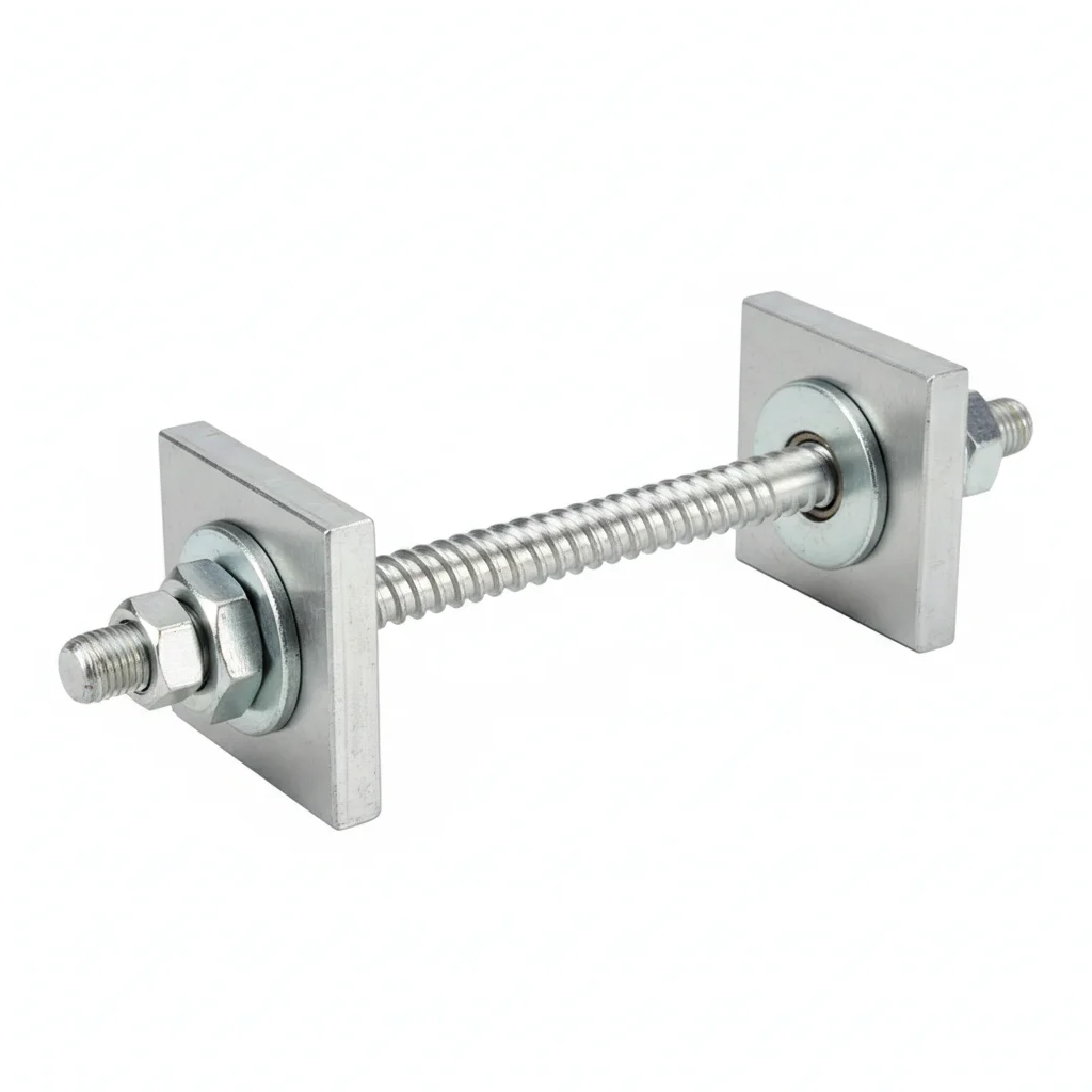
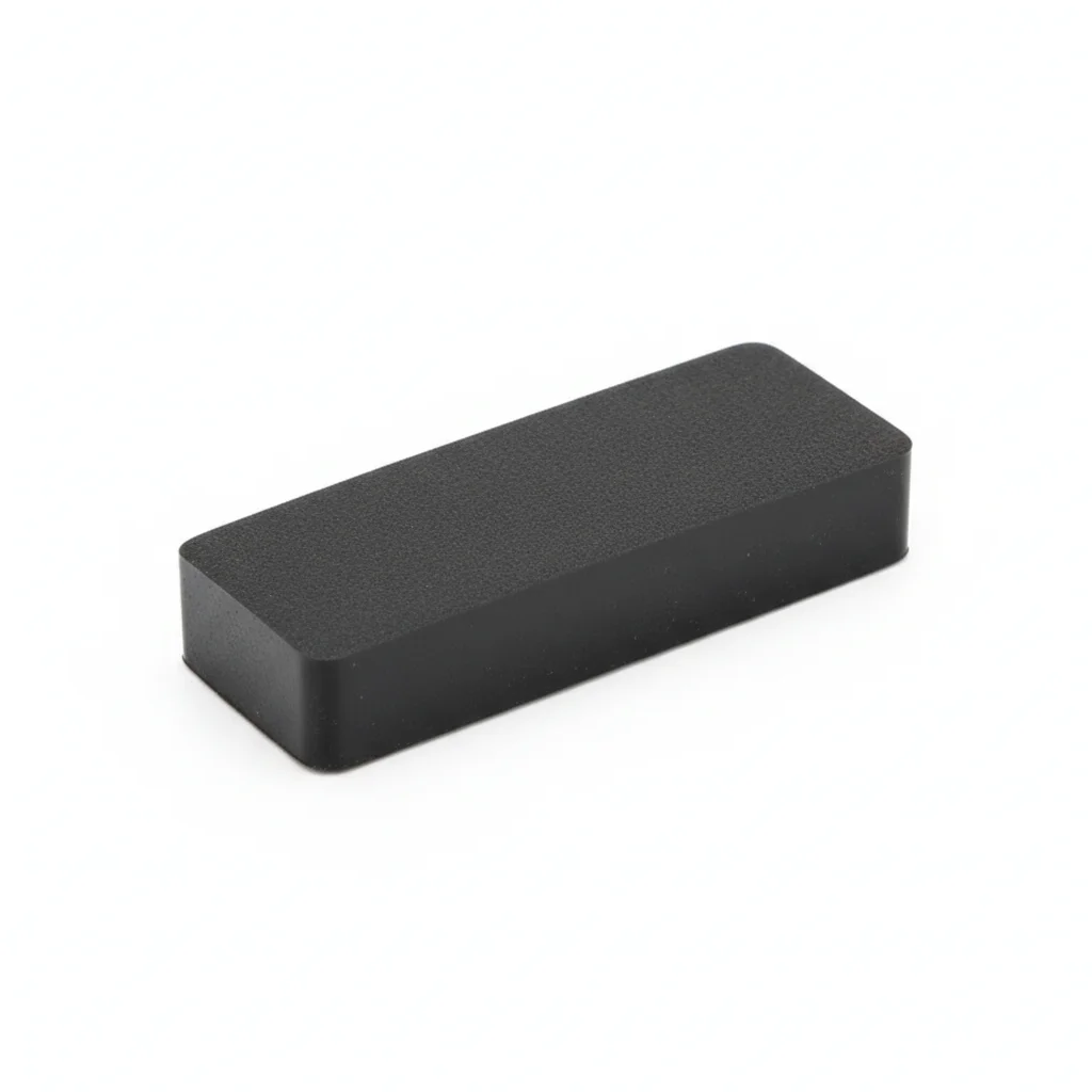
| Buffer Bar | Support Beam | Fixing Bolt | Adjusting Rod | Anti-Slip Shim | |
|---|---|---|---|---|---|
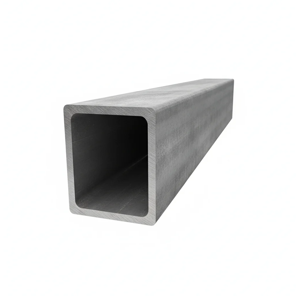
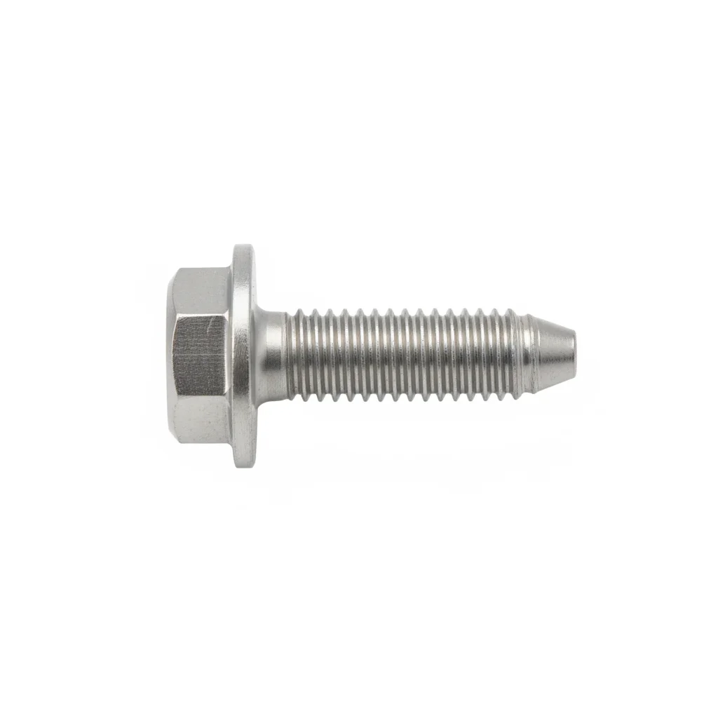
| SPEC | Belt width adaptation 500-1400mm, NR 60A+Al2O3 ceramic inserts | Q235B hot-dip galvanized, adjustable spacing 300mm | M16×80, Grade 8.8 Dacromet coating | M20×200, height fine adjustment ±30mm | EPDM rubber pad, friction coefficient >0.5 |
| MATERIAL | NR | Q235B | — | — | EPDM |
| GRADE | — | — | Grade 8.8 | — | — |
| FINISH | HDG >=55um per ISO 1461 | HDG >=55um per ISO 1461 | HDG >=55um per ISO 1461 | HDG >=55um per ISO 1461 | HDG >=55um per ISO 1461 |
| CORROSION | C3 (ISO 12944-2) | C3 (ISO 12944-2) | C3 (ISO 12944-2) | C3 (ISO 12944-2) | C3 (ISO 12944-2) |
| TEMP | -20°C to +80°C | -20°C to +80°C | -20°C to +80°C | -20°C to +80°C | -20°C to +80°C |
| WEIGHT | ~0.5 kg/piece | ~0.5 kg/piece | ~0.5 kg/piece | ~0.5 kg/piece | ~0.5 kg/piece |
| MOQ | 100 pcs | 100 pcs | 100 pcs | 100 pcs | 100 pcs |
| PACK | VCI paper + carton | VCI paper + carton | VCI paper + carton | VCI paper + carton | VCI paper + carton |
| STD | ISO 898-1, GB/T 3098.1 | ISO 898-1, GB/T 3098.1 | ISO 898-1, GB/T 3098.1 | ISO 898-1, GB/T 3098.1 | ISO 898-1, GB/T 3098.1 |
| USE | NR 60A+Al2O3 ceramic inserts | Adjustable spacing 300mm | Grade 8.8 Dacromet coating | Height fine adjustment ±30mm | Friction coefficient >0.5 |
PROCEDURE
- Align the M16×80 Grade 8.8 Dacromet fixing bolts with the Q235B support beam holes, ensuring the EPDM anti-slip shims are seated properly.
- Hand-tighten the bolts, then use a calibrated torque wrench to tighten in a star pattern to the specified torque for Grade 8.8 M16 fasteners.
- Adjust the M20×200 adjusting rods to set the desired buffer bar height, verifying the ±30mm fine adjustment range.
- Check that the NR 60A buffer bar with Al2O3 ceramic inserts sits flat against the support beam without gaps.
- Verify all fasteners are properly seated and mark them with torque seal paint for visual inspection.
COMMON ERRORS
| ✕ WRONG | CONSEQUENCE | ✓ CORRECT |
|---|---|---|
| Using a lower grade bolt than Grade 8.8 for the M16×80 fixing bolt | The bolt may plastically deform under repeated impact, causing a gap between the buffer bar and frame, leading to belt flexing and potential longitudinal tear. | Always use the specified Grade 8.8 Dacromet coated bolts and check the grade marking before installation. |
| Overtightening the M16 bolts beyond the recommended torque | Excessive preload can cause bolt elongation or thread stripping, reducing clamping force and leading to premature loosening. | Use a calibrated torque wrench and follow the torque specification for Grade 8.8 M16 bolts; do not exceed the recommended value. |
MAINTENANCE
Inspect buffer bar gaps each shift, adjusting if gap exceeds 3mm. Check bolt tightness at each overhaul window and re-torque if below 80% of specified torque. Verify the NR 60A hardness and ceramic insert condition; replace when rubber wear exceeds 40% of original thickness or ceramic detachment area exceeds 20%.
Plan B · Polyurethane Heavy-Duty Impact Bed
C4 Harsh per ISO 12944-2
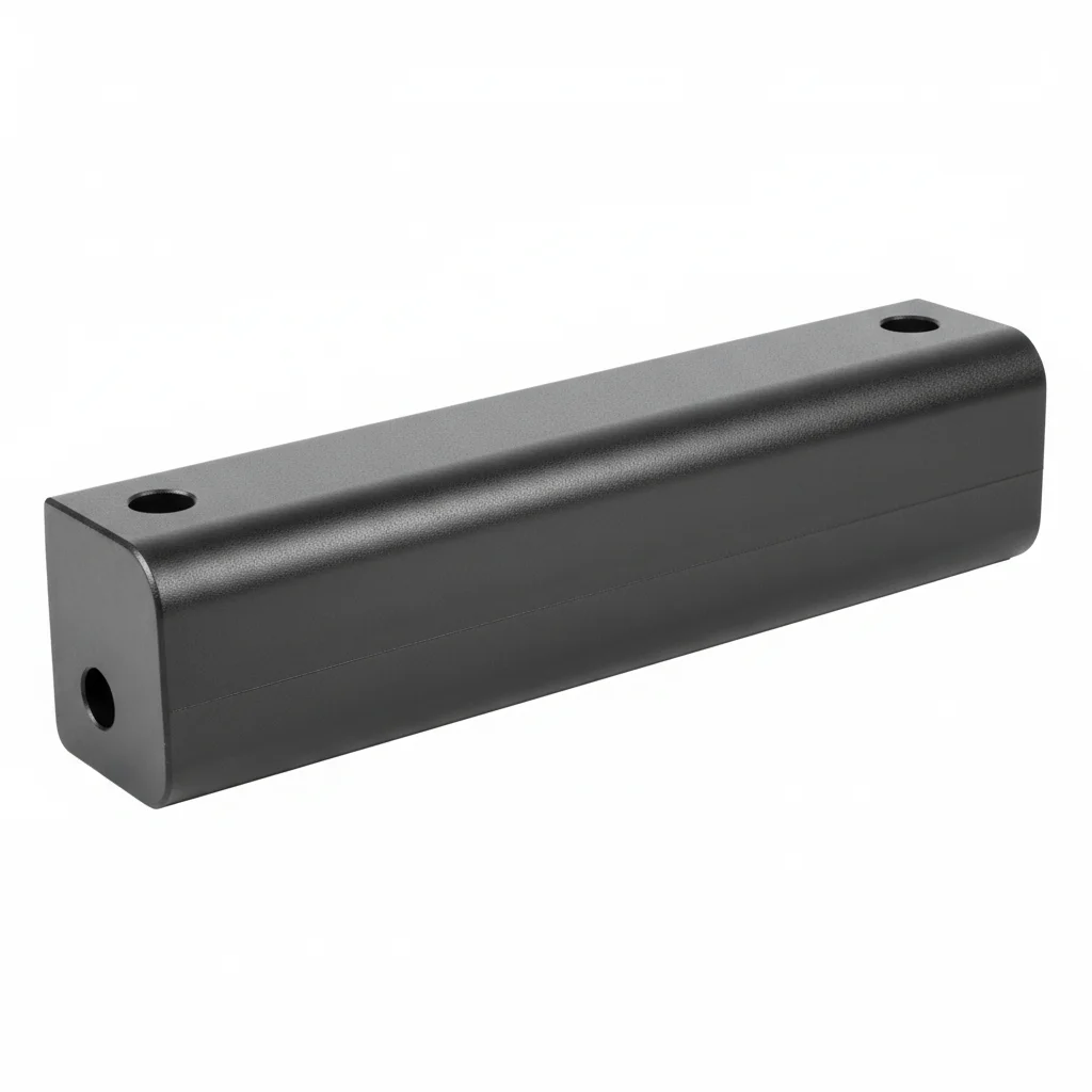
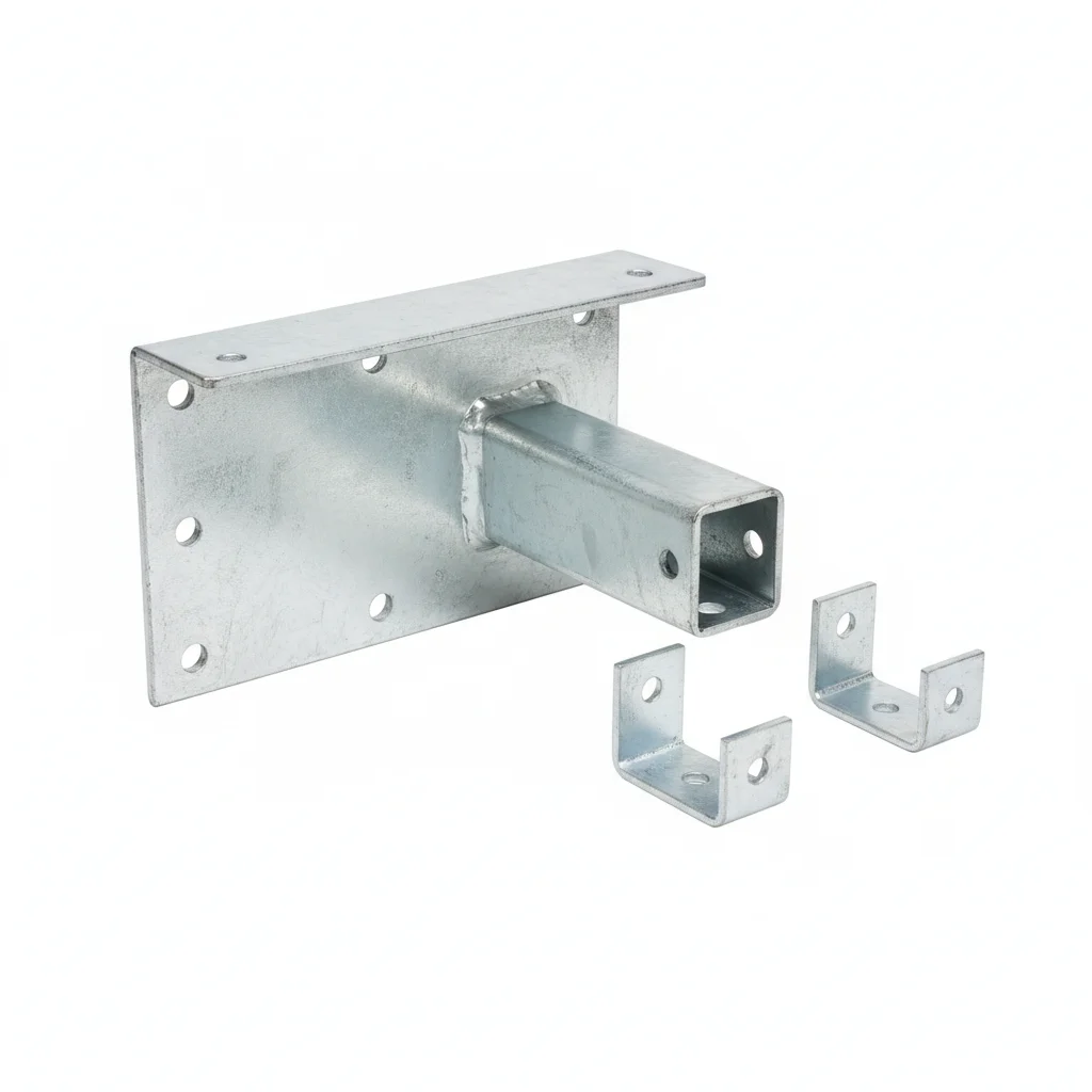
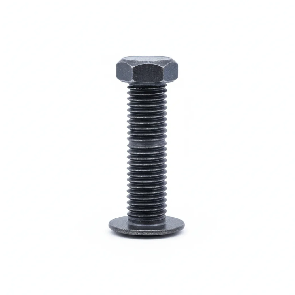
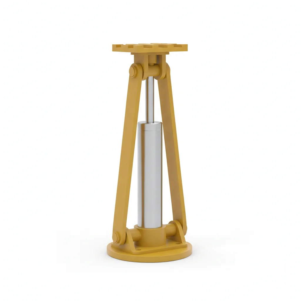
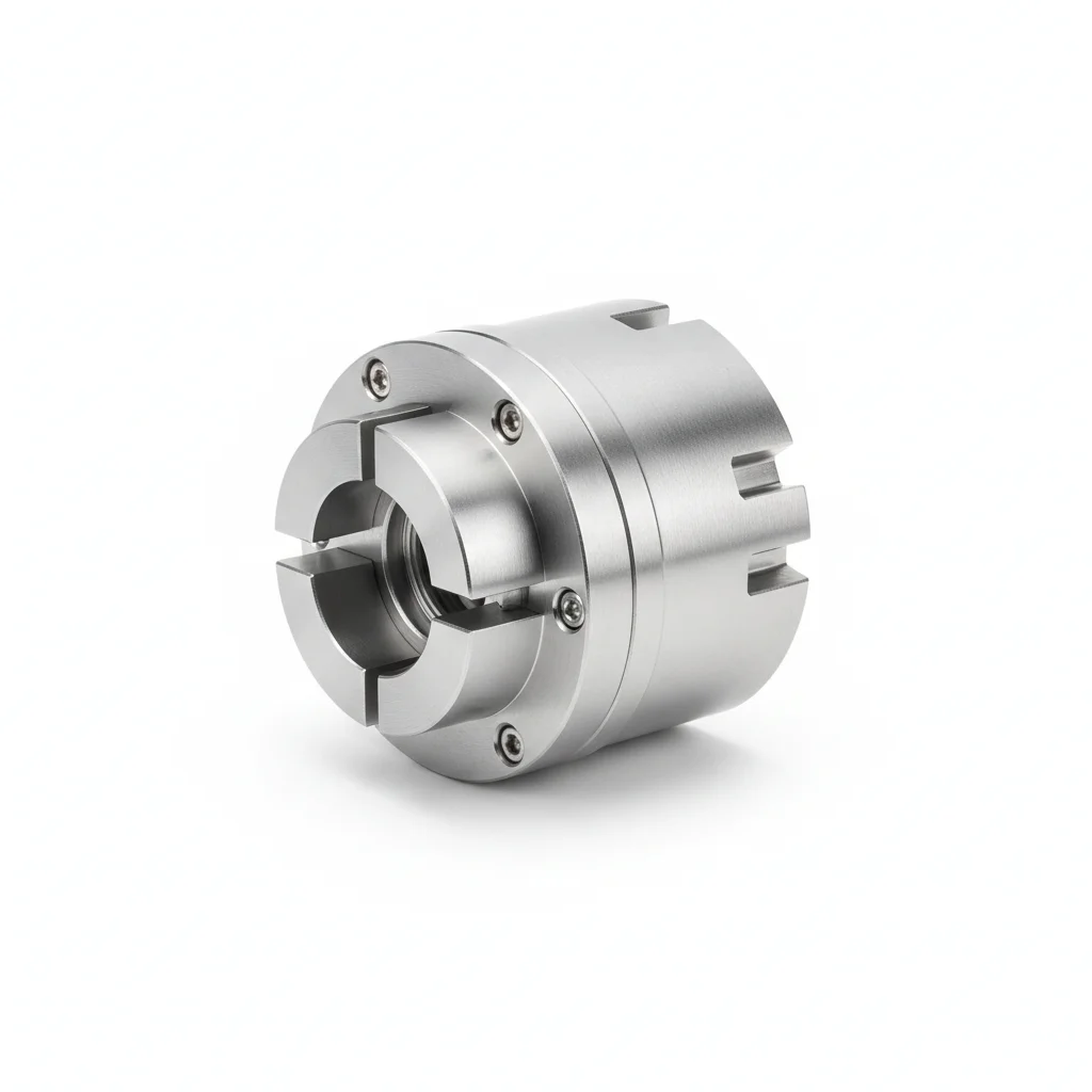
| Heavy-Duty Buffer Bar | Reinforced Bracket | High-Strength Fixing Bolt | Hydraulic Lifting Device | Quick-Release Connector | |
|---|---|---|---|---|---|
| SPEC | Belt width adaptation 800-2000mm, PU 80A+WC-Co wear layer | Q345B welded structure, load capacity ≥50kN/m | M20×100, Grade 10.9 phosphated anti-seize | Stroke 50mm, adapts to belt sag changes | Tool-free buffer bar replacement, downtime <15 minutes |
| MATERIAL | PU | Q345B | — | — | — |
| GRADE | — | — | Grade 10.9 | — | — |
| FINISH | HDG >=55um per ISO 1461 | HDG >=55um per ISO 1461 | HDG >=55um per ISO 1461 | HDG >=55um per ISO 1461 | HDG >=55um per ISO 1461 |
| CORROSION | C3 (ISO 12944-2) | C3 (ISO 12944-2) | C3 (ISO 12944-2) | C3 (ISO 12944-2) | C3 (ISO 12944-2) |
| TEMP | -20°C to +80°C | -20°C to +80°C | -20°C to +80°C | -20°C to +80°C | -20°C to +80°C |
| WEIGHT | ~0.5 kg/piece | ~0.5 kg/piece | ~0.5 kg/piece | ~0.5 kg/piece | ~0.5 kg/piece |
| MOQ | 100 pcs | 100 pcs | 100 pcs | 100 pcs | 100 pcs |
| PACK | VCI paper + carton | VCI paper + carton | VCI paper + carton | VCI paper + carton | VCI paper + carton |
| STD | ISO 898-1, GB/T 3098.1 | ISO 898-1, GB/T 3098.1 | ISO 898-1, GB/T 3098.1 | ISO 898-1, GB/T 3098.1 | ISO 898-1, GB/T 3098.1 |
| USE | PU 80A+WC-Co wear layer | Load capacity ≥50kN/m | Grade 10.9 phosphated anti-seize | Adapts to belt sag changes | Downtime <15 minutes |
PROCEDURE
- Degrease the mounting surface with acetone to remove grease and dust, then confirm surface roughness Ra <3.2μm for optimal bolt seating.
- Position the reinforced Q345B bracket with load capacity ≥50kN/m, aligning it to the conveyor centerline. Insert Grade 10.9 phosphated anti-seize bolts (M20×100) through the bracket and frame.
- Tighten bolts in a cross-pattern sequence to ensure even load distribution. Use a calibrated torque wrench to achieve the specified preload, checking 10% of fasteners with a verification tool.
- Install the hydraulic lifting device (stroke 50mm) to adjust for belt sag, then secure the quick-release connector for tool-free buffer bar replacement.
- Verify the PU 80A buffer bar sits flush with the belt, ensuring no gaps >3mm. Conduct a pull-test on 5% of bolts to 80% proof load, replacing any that fail.
COMMON ERRORS
| ✕ WRONG | CONSEQUENCE | ✓ CORRECT |
|---|---|---|
| Using Grade 8.8 bolts instead of Grade 10.9 for the heavy-duty impact bed | Under high drop impact (>3m), Grade 8.8 bolts plastically deform and elongate, creating gaps that lead to belt tearing and premature failure. | Always use Grade 10.9 phosphated anti-seize bolts (M20×100) specified for Plan B; verify hardness and coating before installation. |
| Neglecting to adjust the hydraulic lifting device after installation | Belt sag changes go uncompensated, causing uneven impact distribution and accelerated wear on the PU buffer bar. | After initial tightening, use the hydraulic lifting device to fine-tune the buffer bar height, ensuring it contacts the belt evenly across the full width. |
MAINTENANCE
At each overhaul window, inspect bolt torque; re-torque any fastener below 80% of specified torque. Replace bolts showing corrosion >5% surface area or pitting depth >0.3mm. Check the quick-release connector for wear and verify the hydraulic lifting device maintains stroke within 50mm. Monitor buffer bar wear; replace when PU wear layer is <10mm from bolt head.
Plan C · Ceramic Composite Extreme Impact Bed
C5-M Extreme per ISO 12944-2
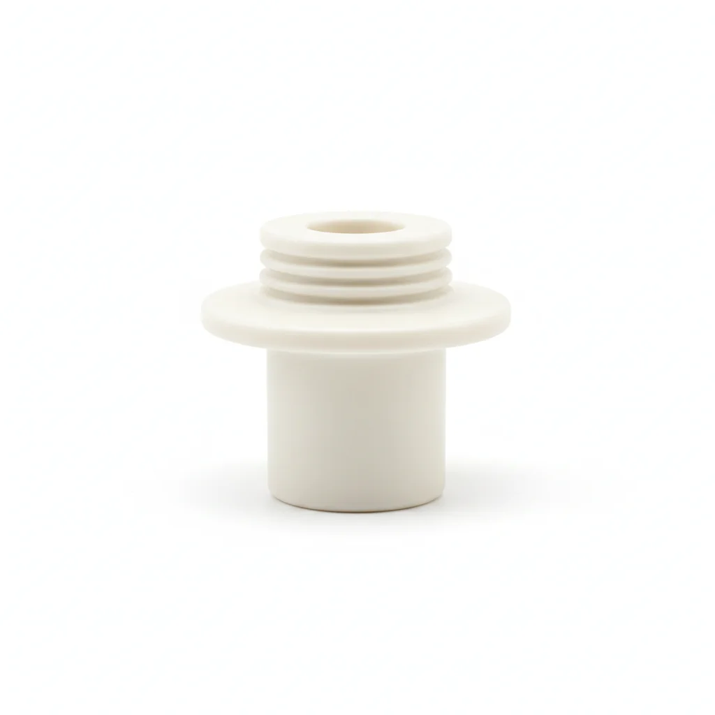
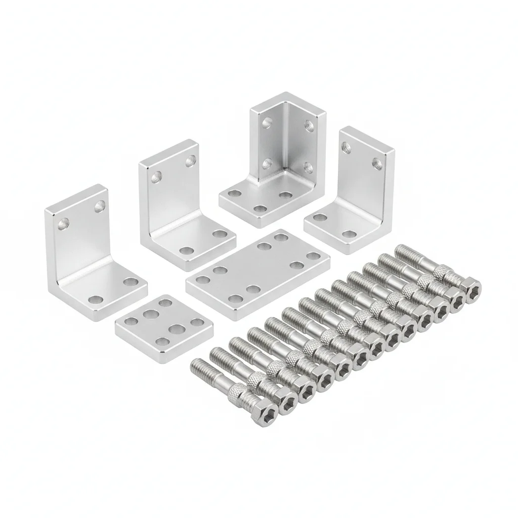
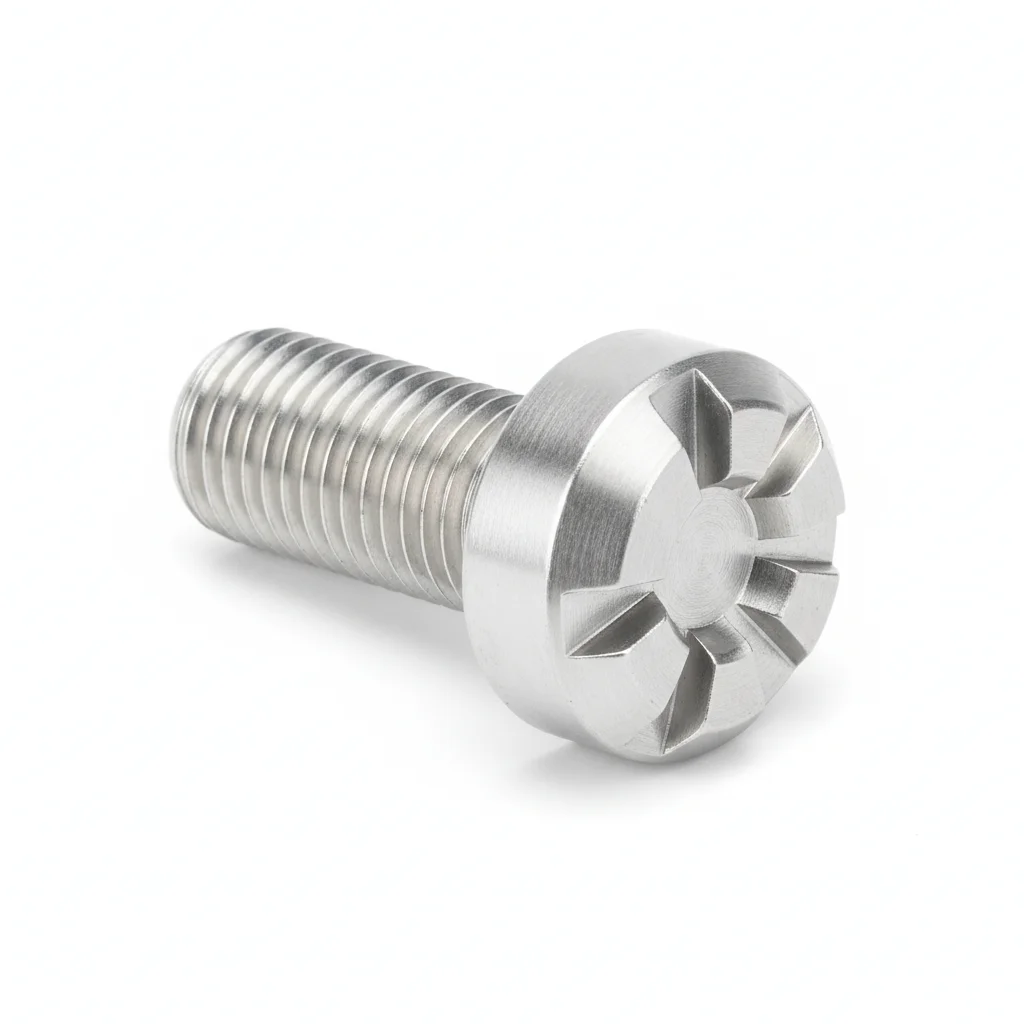
| Ceramic Buffer Module | Modular Bracket | Special Alloy Bolt | Intelligent Wear Monitoring | Automatic Leveling System | |
|---|---|---|---|---|---|
| SPEC | Belt width adaptation 1000-2400mm, Al2O3 ceramic+high-temperature resistant PU | NM400 wear-resistant steel frame, segmented for easy partial replacement | M24×120, Inconel 625 corrosion and high temperature resistant | Pressure sensor array, real-time feedback of impact force distribution | Electric actuator, maintains constant gap between impact surface and belt |
| MATERIAL | PU | — | — | EPDM Rubber | — |
| GRADE | — | — | — | — | — |
| FINISH | HDG >=55um per ISO 1461 | HDG >=55um per ISO 1461 | HDG >=55um per ISO 1461 | HDG >=55um per ISO 1461 | HDG >=55um per ISO 1461 |
| CORROSION | C3 (ISO 12944-2) | C3 (ISO 12944-2) | C3 (ISO 12944-2) | Not applicable (polymer) | C3 (ISO 12944-2) |
| TEMP | -20°C to +80°C | -20°C to +80°C | -20°C to +80°C | -20°C to +80°C | -20°C to +80°C |
| WEIGHT | ~0.5 kg/piece | ~0.5 kg/piece | ~0.5 kg/piece | ~0.5 kg/piece | ~0.5 kg/piece |
| MOQ | 100 pcs | 100 pcs | 100 pcs | 100 pcs | 100 pcs |
| PACK | VCI paper + carton | VCI paper + carton | VCI paper + carton | VCI paper + carton | VCI paper + carton |
| STD | ISO 898-1, GB/T 3098.1 | ISO 898-1, GB/T 3098.1 | ISO 898-1, GB/T 3098.1 | ISO 898-1, GB/T 3098.1 | ISO 898-1, GB/T 3098.1 |
| USE | Al2O3 ceramic+high-temperature resistant PU | Segmented for easy partial replacement | Inconel 625 corrosion and high temperature resistant | Real-time feedback of impact force distribution | Maintains constant gap between impact surface and belt |
PROCEDURE
- Clean the mounting surface with MEK solvent to remove all contaminants, then verify surface roughness Ra <1.6μm for maximum bond integrity.
- Position the NM400 modular bracket (segmented for partial replacement) and secure with Inconel 625 special alloy bolts (M24×120). Apply PTFE-encapsulated washers to prevent galling.
- Tighten bolts using a hydraulic tensioner to achieve precise preload, following a cross-pattern sequence. Perform PMI verification on 10% of bolts to confirm Inconel 625 composition.
- Install the intelligent wear monitoring system with pressure sensor array, calibrating it to record real-time impact force distribution.
- Set up the automatic leveling system with electric actuator to maintain constant gap between impact surface and belt. Conduct NDT dye penetrant testing on 10% of welds and bolts, replacing any with crack indications.
COMMON ERRORS
| ✕ WRONG | CONSEQUENCE | ✓ CORRECT |
|---|---|---|
| Substituting standard carbon steel bolts for Inconel 625 in high-temperature slag applications | Carbon steel bolts corrode rapidly and lose strength at temperatures above 200°C, leading to catastrophic joint failure and belt damage. | Use only Inconel 625 special alloy bolts (M24×120) specified for Plan C; verify material certification and PMI test results before installation. |
| Skipping the automatic leveling system calibration after installation | Without proper calibration, the impact surface may contact the belt unevenly, causing localized stress and premature ceramic module failure. | After installation, run the automatic leveling system through its full stroke and verify it maintains the designed gap; recalibrate if deviation exceeds 0.3mm. |
MAINTENANCE
Leverage the intelligent wear monitoring system for real-time feedback on impact force distribution; review data at each overhaul. Re-torque any bolt below 80% specified torque. Inspect ceramic buffer modules for detachment >20% of wear layer area or cracks; replace modules as needed. Verify automatic leveling system maintains constant gap; recalibrate if deviation exceeds 0.3mm.
REFERENCED STANDARDS
Technical Basis and Reference Standards
Belt Conveyors
Mining Product Safety MarkContinuous handling equipment and systems - Design rules for belt conveyors
Belt ConveyorTechnical Conditions for Coal Mine Belt Conveyors
Belt Conveyor DesignTextile Fabric Core Conveyor Belts for General Use
Belt ConveyorStandard Test Method for Rubber Property—Durometer Hardness
SUPPLIER CAPABILITY
Quality, Delivery & Customization
Quality Control
- ✓MTC material certificates with every batch
- ✓Key parts sampled for hardness/salt spray/torque coefficient
- ✓100% inspection or AQL sampling before shipment
Delivery
- ✓Standard parts made to order: 7-15 days
- ✓Custom parts: 25-45 days
- ✓FOB/CIF/DDP supported
Customization
- ✓Drawing review and material matching
- ✓Non-standard sizes/heads/threads
- ✓Small-batch prototyping supported
Certification
- ✓Material certificates (MTC)
- ✓Spectrographic analysis reports
- ✓Salt spray test reports (on request)
MOQ: No MOQ for standard parts; custom parts assessed by process complexity
FAQ
Frequently Asked Questions
RELATED READING
Keep Reading & Next Step
BEYOND TECHNICAL SPECS
Finding the right factory, controlling quality, delivering on time — that's the real challenge. We cover fasteners, rubber, plastics, industrial textiles. One team, end to end.
SEE CAPABILITIES →