Mine Ventilation Ducts: Material Comparison for Air Leakage and Durability
Select the right duct material based on ventilation distance, humidity, and temperature. Compare PVC standard, CR wire-reinforced, and NBR canvas options with focus on connector sealing, hanging hardware, and repair methods to minimize air leakage and ensure safety
RISK AUDIT // ENGINEERING DIAGNOSIS
Procurement Pitfall Guide
"Common pitfalls in mine ventilation duct selection and installation."
QC-AUDIT // REV.5
SCALE 1:1 · 03 ITEMS
RISK-01
Quick Duct Connector Loosening Under Airflow Pulsation
Corrective Measures
RISK-02
PVC Duct Brittle Fracture Failure in Low Temperature Environments
Corrective Measures
RISK-03
Rapid Corrosion and Mildew of Canvas Ducts in Corrosive Gas and High Humidity Environments
Corrective Measures
FIELD-SPECIFIC INSIGHT
Connector and Hanger Selection for Duct Air Leakage Control
Air leakage in mine ventilation ducts is often caused not by the duct material itself but by loose connectors, degraded seals, or improper hanger spacing. The quick-connect steel ring clamp, flange bolts, and hanger hooks must be specified with the correct material and torque to withstand airflow pulsation and corrosion
WHAT TO CHECK
- 1Steel ring clamp connectors on PVC ducts: EPDM seal elasticity decays after 10^6 pulsations (3-6 months) → re-torque or replace to prevent separation
- 2Flange connectors on CR ducts: Use fluororubber gaskets for humid environments
- 3Hanger spacing: 3m for PVC ducts (PA66 hooks) vs 2m for CR ducts (304 U-hooks, load ≥30kg/m) to prevent sagging and joint stress
- 4Repair tape for PVC (self-adhesive) vs CR adhesive patch (curing 2h): emergency repair method affects downtime and leak rate
| Check | Why it matters | What to specify |
|---|---|---|
| Connector type and seal material | Airflow pulsation can loosen connectors, causing duct separation and gas accumulation risk | Steel ring clamp with EPDM seal for PVC; steel flange with fluororubber gasket for CR; cam lock for NBR |
| Hanger material and spacing | Incorrect spacing or weak hangers cause duct sagging, increasing joint stress and air leakage | PA66 hooks at 3m for PVC; 304 U-hooks at 2m for CR; reinforced wire rope with auto-tensioning for NBR |
| Repair method availability | Rapid repair of duct damage prevents air leakage escalation and maintains ventilation efficiency | PVC self-adhesive tape for emergency; CR adhesive patch for permanent repair; include in maintenance kit |
| Grounding wire for anti-static ducts | Static discharge in high-gas mines can cause explosions; grounding wire must be properly connected | Copper braided tape ≥16mm² cross-section, reliably grounded per mine safety standards |
Air leakage rate data and specific torque values should be confirmed with supplier test reports for your project conditions
Evidence level: source-page-only
INDUSTRY TECH REFERENCE
Air-Leakage Acceptance: Which Figure Governs Which Segment
Leak-rate figures on an offer often mix three dimensions: positive vs negative pressure, product acceptance vs in-service evaluation, and which duct-run segment the number applies to. Lay out the four verifiable criteria by authority level, then accept against the right one.
| Criterion | Value | Governs / authority |
|---|---|---|
| Positive-pressure duct, per-100-metre leak rate | ≤4.0% | Product-standard limit (MT/T 164-2007 Table 3) — acceptance for forced-air runs |
| Negative-pressure duct, per-100-metre leak rate | ≤5.0% | Product-standard limit (MT/T 165-2007 Table 4) — acceptance for exhaust runs |
| In-service tightness (air-leakage coefficient k, GSE 2022, Polish basis) | k≤1.5×10⁻⁵ good; 1.5×10⁻⁵<k≤3×10⁻³ acceptable; k>3×10⁻³ inadequate | Evaluates an existing ventilation system, not goods receiving |
| Total leak-rate limit by duct-run distance | <200 m no more than 15%; 200-500 m no more than 10%; 500-1000 m no more than 3% | Company-policy / training material (medium confidence) — reference for stage acceptance on long runs |
The per-100-metre limits come from MT/T 164-2007 Table 3 and MT/T 165-2007 Table 4 (public PDFs, National Mine Safety Administration)[^2][^3]; both standards were voided in 2020-06 and consolidated into MT/T 164-2019 (listed on some platforms as KA/T 164-2019), whose clause text was not line-checked — re-verify before publishing[^4]; the k tiering follows GSE 2022 (VŠB Ostrava, open access)[^17]; the distance-based total limits are Chinese engineering-management material (medium confidence)[^20].
INDUSTRY TECH REFERENCE
When a Joint Leaks: How Airflow Erodes Toward Gas Accumulation
Joint leakage is the most frequent and the most severe duct failure. The chain starts at the seal-failure mechanism, every link carries a verifiable number, and inspection and acceptance follow the same order.
- 1A weak seal (fold-back not pressed home, loose clamp, missing zipper teeth) or a body tear starts the leak — leak rate scales with the square root of differential pressure, so the section nearest the fan, where duct pressure is highest, leaks most
- 2Every leak eats effective airflow at the face — the longer the run, the sooner the tail end comes up short
- 3Shortfall in effective air → gas dilution fails → accumulation. Quantified anchors: size the fan-to-duct-end margin at 35% leakage minimum (NIOSH shaft-sinking guide); with 10,000 cfm through a 24″ exhaust duct set 10 ft from the face, face ventilation efficiency (FVE) is only 0.10 — distance and leakage together decide dilution
- 4Measured verdict, Vietnam: leakage in the auxiliary ducting system is the most common reason face airflow falls short (Quang Ninh / Uong Bi underground coal mines)
- 5The defense: after commissioning, inspect joint clamps, tape seals and joint tightness daily and fix looseness on the spot — hold the leak at its source and the face airflow holds
The mechanism follows archive §2 FM-1 (GSE 2022[^17]): leak rate ∝ square root of differential pressure, most leakage near the fan; the 35% margin (Ch. 9, shaft sinking) and the FVE 0.10 anchor (Ch. 14, tunnel construction: 10,000 cfm, 24″ exhaust duct, 10 ft from the face) come from NIOSH's Handbook for Methane Control in Mining[^16]; "duct leakage is the most common cause of shortfall in face airflow" is a measured finding from Quang Ninh / Uong Bi underground coal mines in Vietnam (E3S Web of Conferences 2021, abstract level, medium-high confidence)[^18]; the daily-inspection practice comes from a duct manufacturer's maintenance guide[^21].
INDUSTRY TECH REFERENCE
Exhaust Duty Is a Different Spec: Lay-Flat Ducts Collapse
On an exhaust face the duct sees negative pressure, not the flipped positive case — it rules out one whole class of hardware. Read this boundary before ordering.
On a negative-pressure circuit the duct sees suction, and a lay-flat coated-fabric duct is sucked flat along its whole length, choking the airflow — negative-pressure runs must use a spring-wire skeleton duct: ABC MineDuct uses a 3″ (76 mm) spring-wire pitch for exhaust and 6″ for forced-air blowing, diameters 8″-48″. For high negative pressure over long runs the mainstream choice is a rigid FRP duct: RigiDuct is explicitly built for high negative pressure, socket-and-coupler with rubber gaskets, round 8″-48″ or oval 14″-45″, in 10/20 ft sections. The boundary is written into the OEM product definitions: the MineDuct skeleton covers both positive and negative pressure, while the MineVent lay-flat is positive-pressure only. Confirm pressure mode before ordering — never supply a lay-flat duct into a negative-pressure circuit.
The collapse risk and the pitch tiering (3″ (76 mm) exhaust / 6″ forced air) come from ABC Industries product bulletins (MineDuct spring-wire duct)[^12][^15]; the RigiDuct high-negative-pressure design and dimensions (round 8″-48″, oval 14″-45″, 10/20 ft sections, socket-and-coupler with rubber gaskets) are from the same source[^12]; "MineDuct covers both pressures, MineVent positive only" is the OEM product-definition boundary[^12].
INDUSTRY TECH REFERENCE
Duct Diameter and Section Length: Chinese vs North American Series
The section-length series sets how many joints a given duct run carries — fewer joints means less clamp hardware and fewer inspection points. Before ordering and at incoming check, match the diameter and section-length series to your duct-run distance.
| Series dimension | Common Chinese stock | N. American OEM |
|---|---|---|
| Diameter range | Φ400/500/600/800/1000 mm (standard series up to 1600 mm) | Lay-flat 12″-120″; skeleton 8″-48″ |
| Section length | 5/10/20 m | 25/50/100 ft |
| Distance-to-diameter mapping (manufacturer practice, medium confidence) | <200 m use Φ400; 200-500 m use Φ500; 500-1000 m use Φ600 | — |
The diameter/length series and the mapping follow archive §5 sizing quick-look[^12][^21]: Chinese stock Φ400/500/600/800/1000 mm (standard series to 1600 mm), sections 5/10/20 m; N. American lay-flat 12″-120″, skeleton 8″-48″, sections 25/50/100 ft; the distance-to-diameter mapping is manufacturer practice (medium confidence)[^21].
INDUSTRY TECH REFERENCE
Duct Joints and Clamps: What to Write on the Order, What to Check at Delivery
Duct coupling is not just one clamp design — China and North America each run their own joint system, with comparable dimensions and clamp counts. Match these five points across inquiry and acceptance.
- Two joint systems: in China, double fold-back seams secured with 12# wire (or steel clamps / quick couplers); in North America, zippers, QuickSnap and grommet-plus-Multi-Clips hardware
- Chinese dimension practice (company-policy, medium confidence): fold-back length 150-200 mm, joint within 200 mm of the section end — put the fold-back dimension in the spec, not just the diameter
- North American clamp count (Rocvent): Multi-Clips spaced 20″-24″ around the circumference, typically 6 for a 42″-48″ duct — count the clamps against the diameter at delivery
- One inspection rhythm: duct manufacturers' maintenance guides require a daily check of joint clamps, tape seals and joint tightness, repeated as the duct is extended with the advancing face
- Protan's official maintenance list is itself the failure-mode list: joints and reducers losing airtightness, hangers and lines jamming, body tears — with a repair kit (adhesive, patches, needle and thread) shipped with the duct: patch on site, there is no wait-for-the-OEM window underground
The joint systems and dimensions (double fold-back with 12# wire / steel clamps / quick couplers; fold-back 150-200 mm, joint within 200 mm of the end — company-policy, medium confidence) follow archive §5 scenario table[^20][^13][^21]; the Multi-Clips 20″-24″ circumference spacing, typically 6 for a 42″-48″ duct, follows the Rocvent joint product page[^13]; the daily inspection and the on-board repair kit (adhesive, patches, needle and thread) come from duct manufacturers' maintenance guides and the Protan product page[^21][^14].
PLAN COMPARISON
Three-Plan Core Parameter Comparison
Compare row by row. Click column headers to jump to plan details.
| A · Plan A · PVC Standard Flame-Retardant Duct | B · Plan B · CR Rubber Wire-Reinforced Heavy-Duty Duct | C · Plan C · NBR Canvas Extreme Duct | |
|---|---|---|---|
| 1. POSITIVE PRESSURE DUCT | |||
| SPEC | φ300-600mm×10m/section, PVC coated fabric + steel wire | φ600-1000mm×20m/section, CR coating + high-strength steel wire | φ800-1200mm×30m/section, NBR + aramid |
| MATERIAL | PVC | Q235B | NBR |
| FINISH | hot-dip galvanized ≥55 μm per ISO 1461 | HDG >=55um per ISO 1461 | HDG >=55um per ISO 1461 |
| 2. QUICK CONNECTOR | |||
| SPEC | Steel ring clamp type, EPDM rubber seal | Steel flange + bolt fastening, sealing gasket fluororubber | Aluminum alloy flange + cam lock, tool-free assembly/disassembly |
| MATERIAL | EPDM | — | Aluminum alloy |
| FINISH | HDG >=55um per ISO 1461 | HDG >=55um per ISO 1461 | HDG >=55um per ISO 1461 |
| 3. HANGER HOOK | |||
| SPEC | PA66 flame-retardant plastic hook, spacing 3m | 304 U-hook, spacing 2m, load capacity ≥30kg/m | Steel wire rope + pulley set, automatic tensioning to prevent sagging |
| MATERIAL | PA66 | 304 | — |
| FINISH | HDG >=55um per ISO 1461 | HDG >=55um per ISO 1461 | HDG >=55um per ISO 1461 |
| 4. REPAIR TAPE | |||
| SPEC | PVC self-adhesive tape, width 50mm, emergency repair | CR adhesive + patch, room temperature curing 2h | RFID chip, recording installation time and inspection records |
| MATERIAL | PVC | — | EPDM Rubber |
| FINISH | HDG >=55um per ISO 1461 | HDG >=55um per ISO 1461 | HDG >=55um per ISO 1461 |
| 5. IDENTIFICATION SIGN | |||
| SPEC | Reflective film, marking specifications and flow direction | Portable anemometer, periodic air leakage rate detection | Copper braided tape, cross-sectional area ≥16mm², reliable grounding |
| FINISH | HDG >=55um per ISO 1461 | HDG >=55um per ISO 1461 | HDG >=55um per ISO 1461 |
Plan A · PVC Standard Flame-Retardant Duct
C3 (ISO 12944-2) for dry tunnels with short-distance ventilation
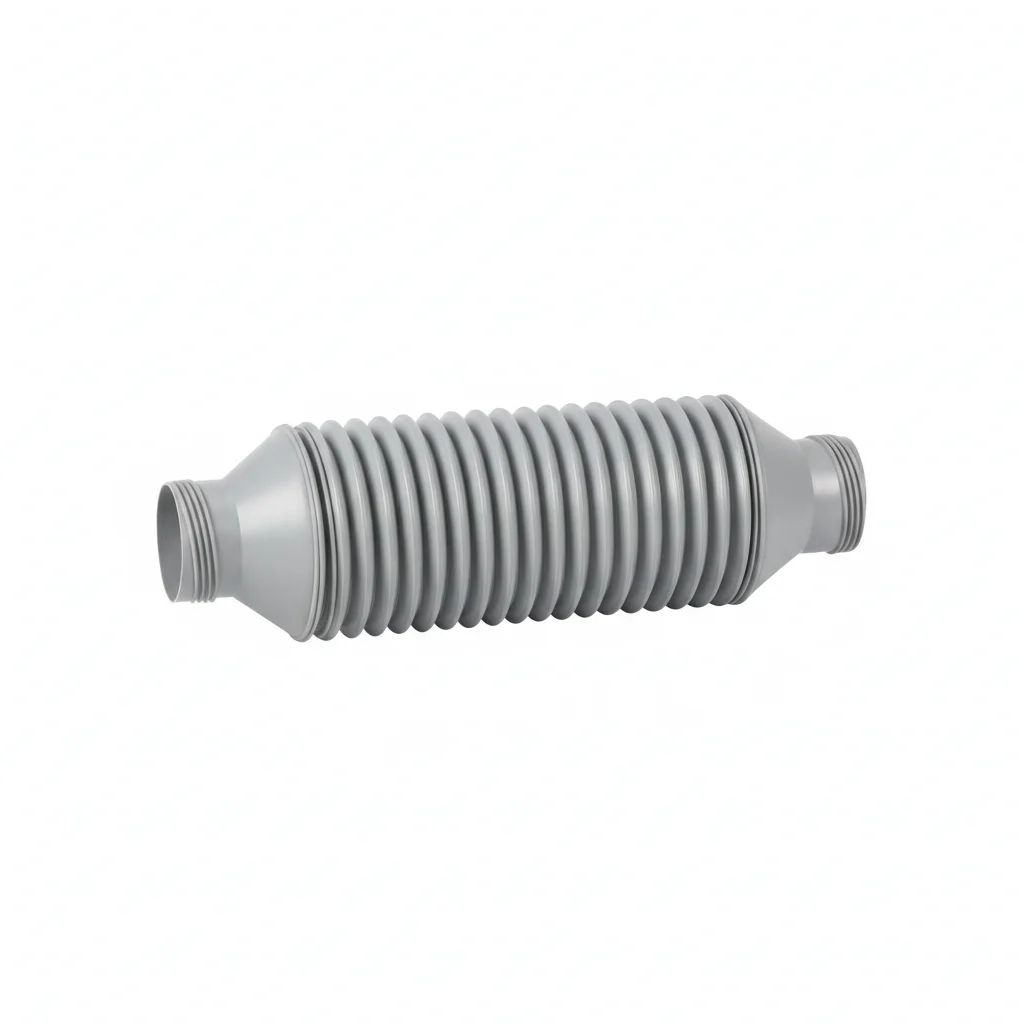
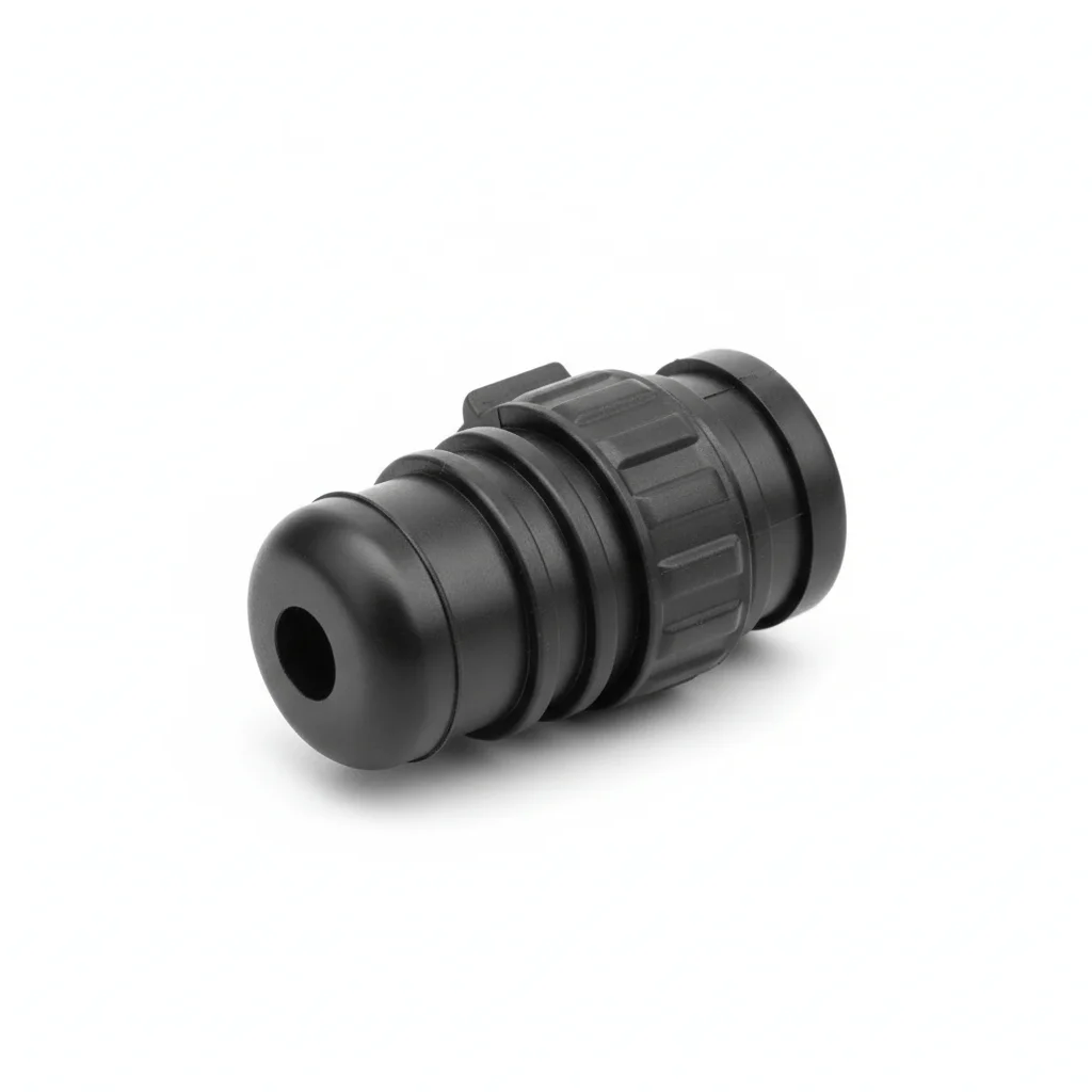
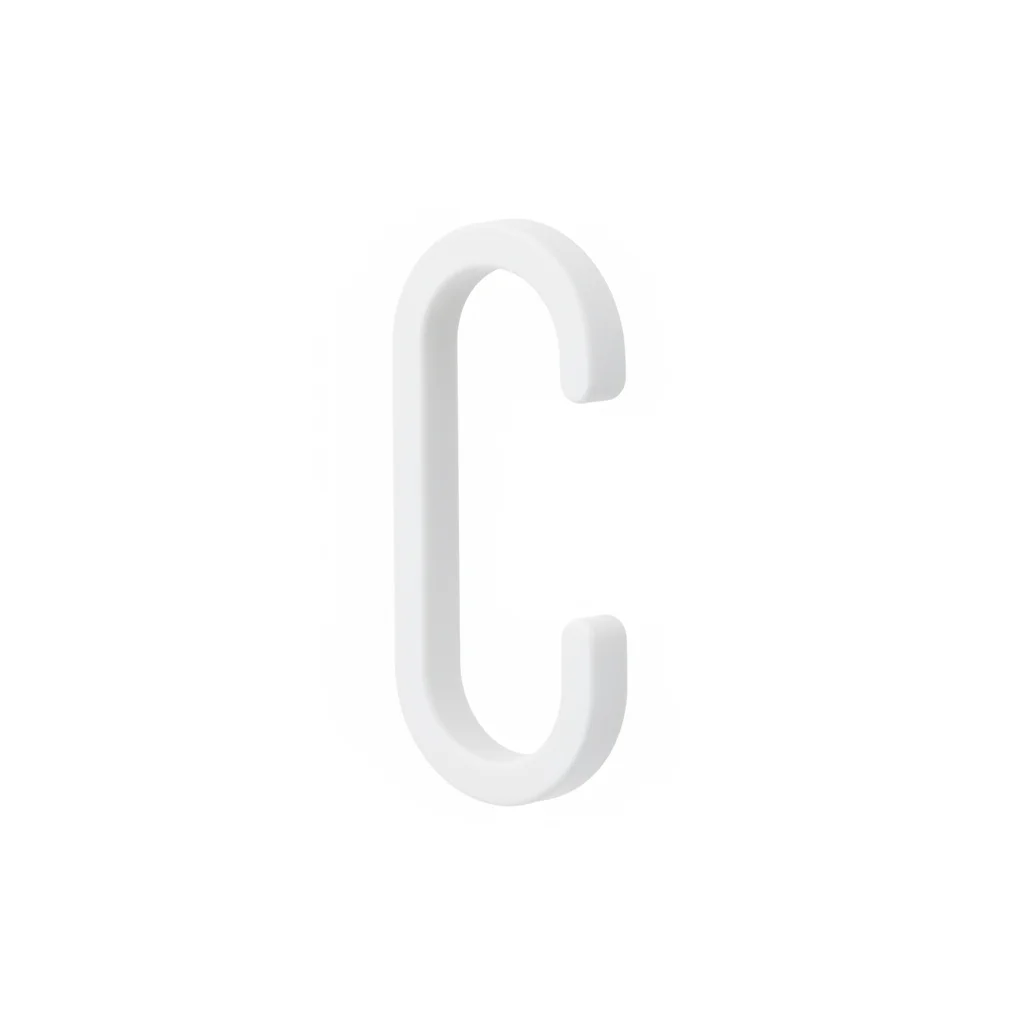
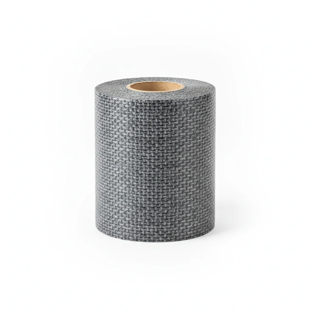
| Positive Pressure Duct | Quick Connector | Hanger Hook | Repair Tape | Identification Sign | |
|---|---|---|---|---|---|
| SPEC | φ300-600mm×10m/section, PVC coated fabric + steel wire | Steel ring clamp type, EPDM rubber seal | PA66 flame-retardant plastic hook, spacing 3m | PVC self-adhesive tape, width 50mm, emergency repair | Reflective film, marking specifications and flow direction |
| MATERIAL | PVC | EPDM | PA66 | PVC | — |
| GRADE | — | — | — | — | — |
| FINISH | hot-dip galvanized ≥55 μm per ISO 1461 | HDG >=55um per ISO 1461 | HDG >=55um per ISO 1461 | HDG >=55um per ISO 1461 | HDG >=55um per ISO 1461 |
| CORROSION | C3 (ISO 12944-2) | C3 (ISO 12944-2) | C3 (ISO 12944-2) | C3 (ISO 12944-2) | C3 (ISO 12944-2) |
| TEMP | -20°C to +80°C | -20°C to +80°C | -20°C to +80°C | -20°C to +80°C | -20°C to +80°C |
| WEIGHT | ~0.5 kg/piece | ~0.5 kg/piece | ~0.5 kg/piece | ~0.5 kg/piece | ~0.5 kg/piece |
| MOQ | 100 pcs | 100 pcs | 100 pcs | 100 pcs | 100 pcs |
| PACK | VCI paper + carton | VCI paper + carton | VCI paper + carton | VCI paper + carton | VCI paper + carton |
| STD | ISO 898-1, GB/T 3098.1 | ISO 898-1, GB/T 3098.1 | ISO 898-1, GB/T 3098.1 | ISO 898-1, GB/T 3098.1 | ISO 898-1, GB/T 3098.1 |
| USE | PVC coated fabric + steel wire | EPDM rubber seal | Spacing 3m | Emergency repair | Marking specifications and flow direction |
PROCEDURE
- Lay out the PVC duct sections on a clean, dry surface, aligning the steel wire reinforcement rings before connecting.
- Insert the male end into the quick connector with the EPDM seal properly seated, ensuring the seal is not twisted.
- Tighten the steel ring clamp evenly using a torque wrench to the specified value, alternating sides to avoid seal distortion.
- Attach PA66 hanger hooks at 3m intervals, ensuring the duct is free of sagging and the hooks are fully engaged.
- Apply PVC repair tape to any minor abrasions or punctures immediately to prevent air leakage during operation.
COMMON ERRORS
| ✕ WRONG | CONSEQUENCE | ✓ CORRECT |
|---|---|---|
| Overtightening the steel ring clamp, crushing the EPDM seal | Seal loses elasticity, causing air leaks and potential duct separation under airflow pulsation. | Tighten to the manufacturer's recommended torque using a calibrated wrench; verify seal compression visually. |
| Spacing hanger hooks more than 3m apart | Duct sags, forming water pockets and increasing joint stress, leading to premature connector failure. | Use PA66 hooks at 3m intervals as specified; for longer spans, add intermediate support. |
MAINTENANCE
Inspect connector clamps and EPDM seals seasonally, re-tightening any loose clamps to the specified torque. Check hanger hooks for deformation or wear, replacing any damaged PA66 hooks immediately. Repair any duct damage with the PVC repair tape at the first sign of leakage.
Plan B · CR Rubber Wire-Reinforced Heavy-Duty Duct
Humid, corrosive underground environment with airflow pulsation; C4 harsh per ISO 12944-2
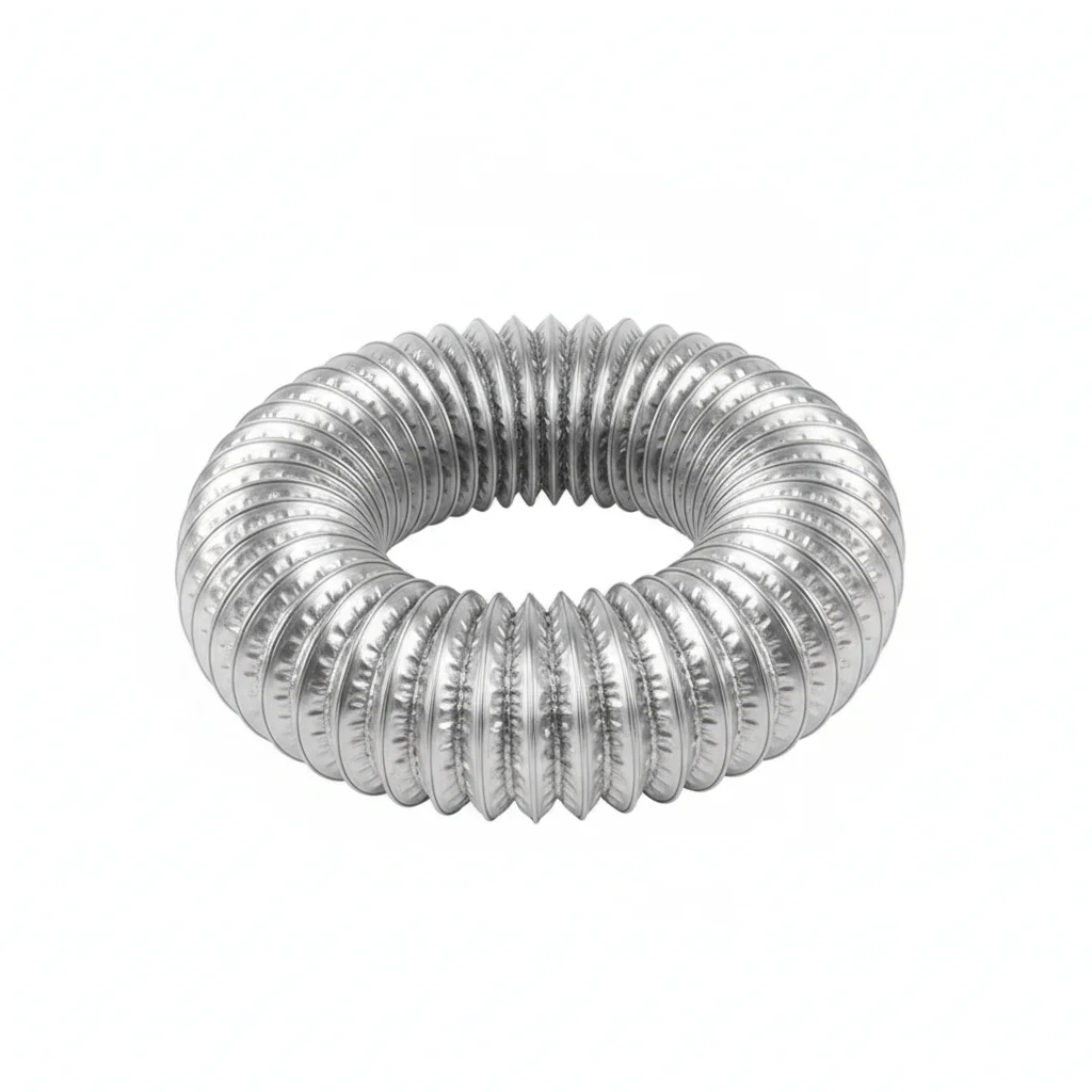
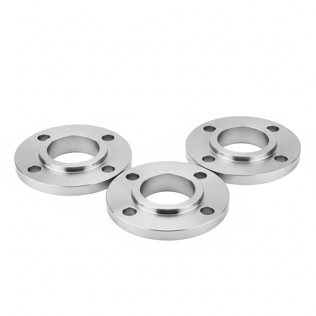
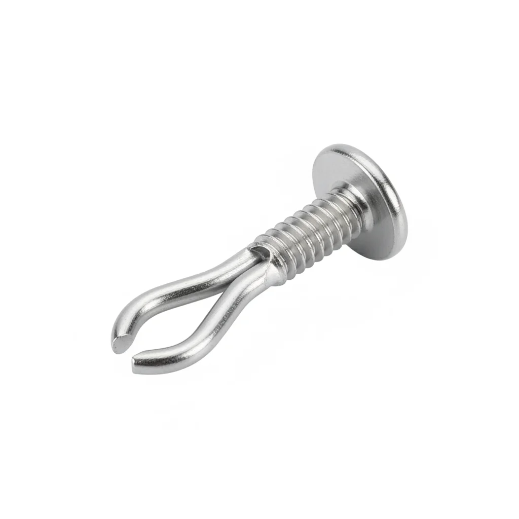
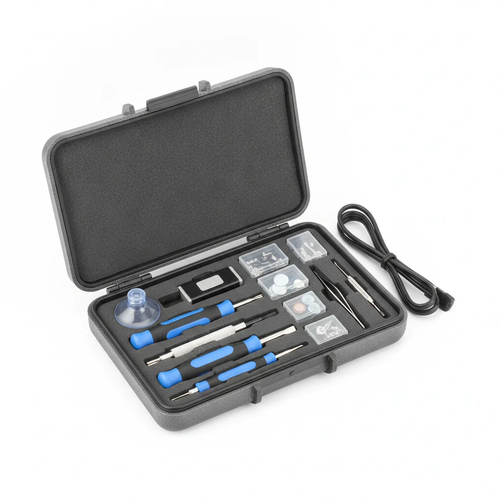
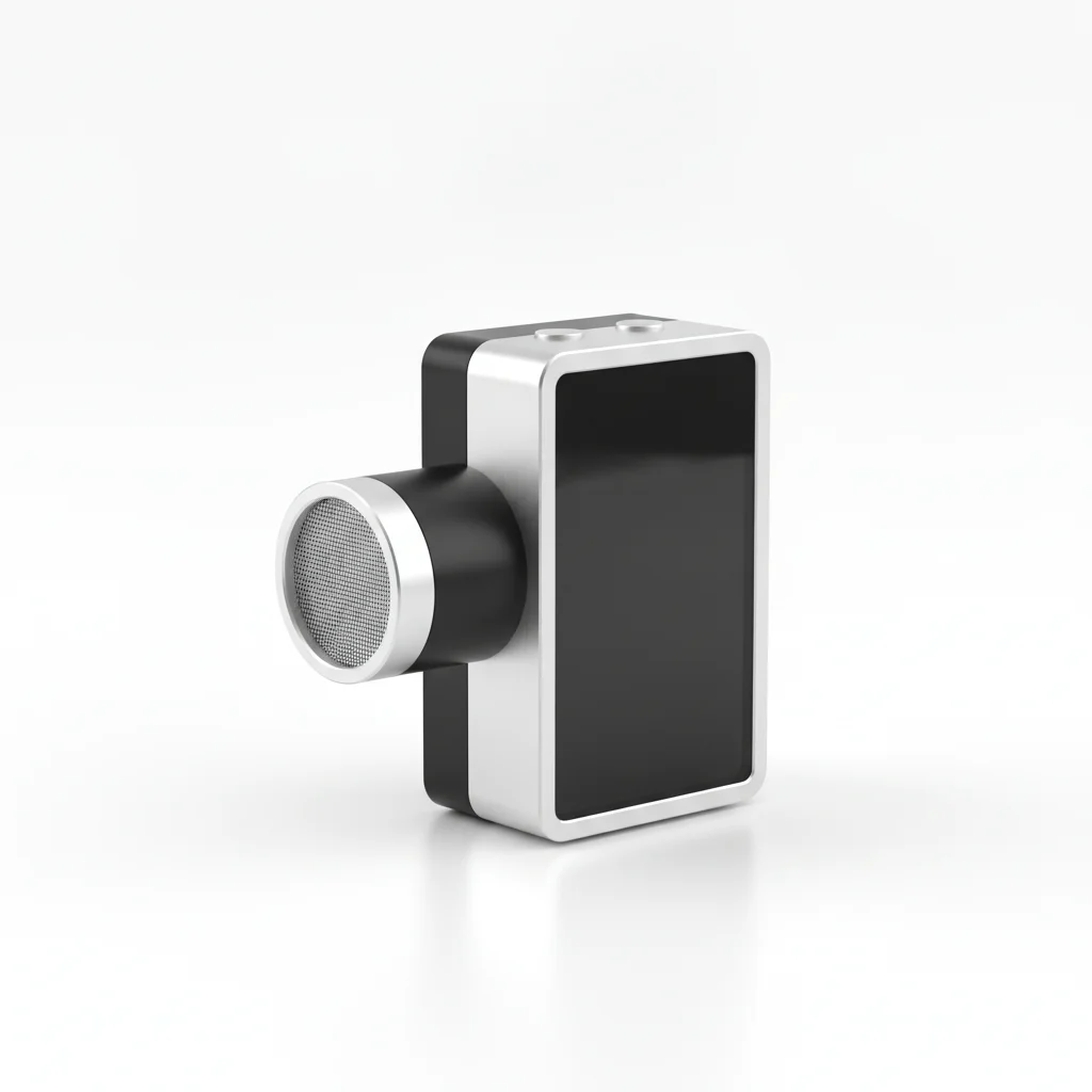
| Wire-Reinforced Duct | Flange Connector | Hanger Hook | Dedicated Repair Kit | Airflow Monitor | |
|---|---|---|---|---|---|
| SPEC | φ600-1000mm×20m/section, CR coating + high-strength steel wire | Steel flange + bolt fastening, sealing gasket fluororubber | 304 U-hook, spacing 2m, load capacity ≥30kg/m | CR adhesive + patch, room temperature curing 2h | Portable anemometer, periodic air leakage rate detection |
| MATERIAL | Q235B | — | 304 | — | — |
| GRADE | — | — | — | — | — |
| FINISH | HDG >=55um per ISO 1461 | HDG >=55um per ISO 1461 | HDG >=55um per ISO 1461 | HDG >=55um per ISO 1461 | HDG >=55um per ISO 1461 |
| CORROSION | C3 (ISO 12944-2) | C3 (ISO 12944-2) | C3 (ISO 12944-2) | C3 (ISO 12944-2) | C3 (ISO 12944-2) |
| TEMP | -20°C to +80°C | -20°C to +80°C | -20°C to +80°C | -20°C to +80°C | -20°C to +80°C |
| WEIGHT | ~0.5 kg/piece | ~0.5 kg/piece | ~0.5 kg/piece | ~0.5 kg/piece | ~0.5 kg/piece |
| MOQ | 100 pcs | 100 pcs | 100 pcs | 100 pcs | 100 pcs |
| PACK | VCI paper + carton | VCI paper + carton | VCI paper + carton | VCI paper + carton | VCI paper + carton |
| STD | ISO 898-1, GB/T 3098.1 | ISO 898-1, GB/T 3098.1 | ISO 898-1, GB/T 3098.1 | ISO 898-1, GB/T 3098.1 | ISO 898-1, GB/T 3098.1 |
| USE | CR coating + high-strength steel wire | Sealing gasket fluororubber | Load capacity ≥30kg/m | Room temperature curing 2h | Periodic air leakage rate detection |
PROCEDURE
- Lay out the CR wire-reinforced duct sections on clean ground, inspect the steel wire helix for any kinks or damage before lifting.
- Align the steel flanges of adjacent sections; insert the fluororubber gasket evenly, ensuring no wrinkles or gaps.
- Bolt the flanges together in a cross-pattern, tightening gradually to achieve uniform compression of the gasket.
- Suspend the duct using 304 U-hooks spaced at 2m intervals, ensuring the load capacity ≥30kg/m is not exceeded.
- After assembly, run a portable anemometer along the joints to identify any air leaks; re-tighten or adjust as needed.
- For any minor damage, apply the CR adhesive patch and allow 2h room-temperature curing before putting the duct back into service.
COMMON ERRORS
| ✕ WRONG | CONSEQUENCE | ✓ CORRECT |
|---|---|---|
| Using standard rubber gaskets instead of fluororubber on flanges in humid environments | Gasket degrades quickly, leading to air leakage and reduced ventilation efficiency at the face. | Always use the fluororubber sealing gasket provided with the flange connector; replace if hardened or cracked. |
| Hanging the duct at 3m spacing as used for PVC, rather than the specified 2m for CR | Excessive sagging creates water pockets and increases stress on joints, accelerating air leakage. | Follow the 2m spacing requirement with 304 U-hooks rated for ≥30kg/m to maintain proper tension. |
| Attempting a quick repair with PVC tape on a CR duct tear | Tape does not bond to CR rubber, leaving the leak unsealed and risking further damage. | Use the dedicated CR repair kit—clean the area, apply adhesive, patch, and allow 2h curing before resuming airflow. |
MAINTENANCE
Inspect flange bolts and hanger hooks at each scheduled maintenance window or after any detected airflow pulsation event; re-torque loose bolts and replace corroded 304 hooks. Check the fluororubber gaskets for hardening or cracking and replace as needed. Monitor air leakage rate periodically with the portable anemometer—if leakage exceeds the <5% target, locate and seal leaks promptly.
Plan C · NBR Canvas Extreme Duct
High-temperature, high-gas, potentially explosive atmosphere; C5-M extreme per ISO 12944-2
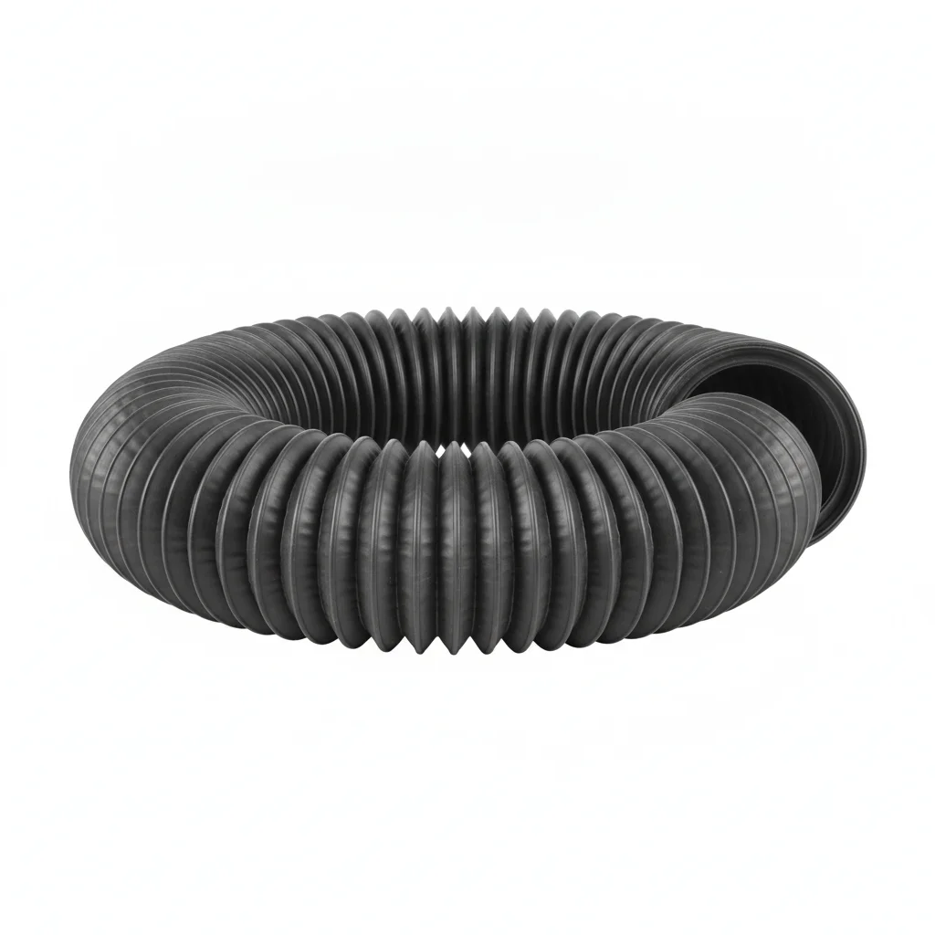
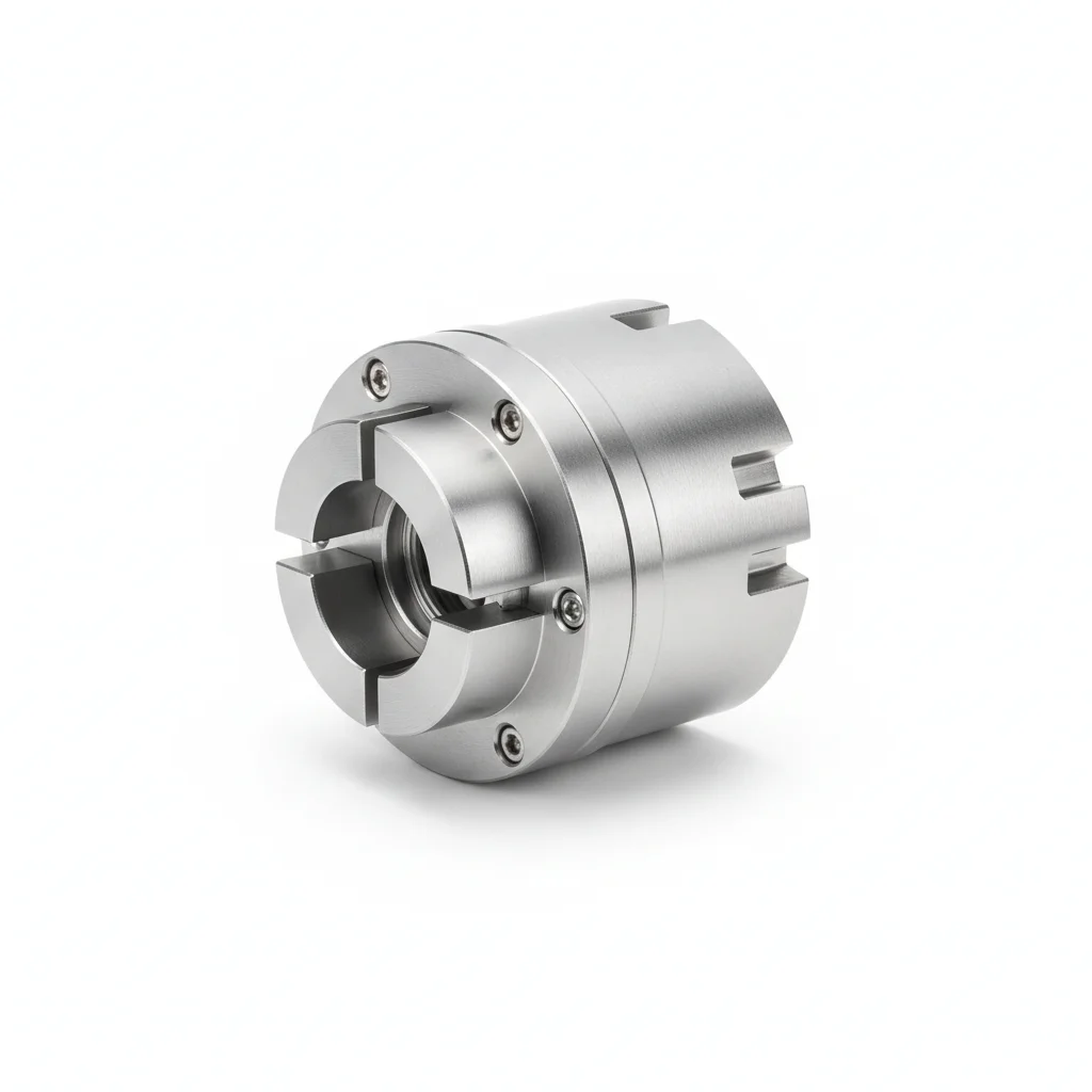
| Canvas Positive Pressure Duct | Quick-Release Metal Connector | Reinforced Hanging System | Smart Monitoring Tag | Anti-Static Grounding Wire | |
|---|---|---|---|---|---|
| SPEC | φ800-1200mm×30m/section, NBR + aramid | Aluminum alloy flange + cam lock, tool-free assembly/disassembly | Steel wire rope + pulley set, automatic tensioning to prevent sagging | RFID chip, recording installation time and inspection records | Copper braided tape, cross-sectional area ≥16mm², reliable grounding |
| MATERIAL | NBR | Aluminum alloy | — | EPDM Rubber | — |
| GRADE | — | — | — | — | — |
| FINISH | HDG >=55um per ISO 1461 | HDG >=55um per ISO 1461 | HDG >=55um per ISO 1461 | HDG >=55um per ISO 1461 | HDG >=55um per ISO 1461 |
| CORROSION | C3 (ISO 12944-2) | C3 (ISO 12944-2) | C3 (ISO 12944-2) | Not applicable (polymer) | C3 (ISO 12944-2) |
| TEMP | -20°C to +80°C | -20°C to +80°C | -20°C to +80°C | -20°C to +80°C | -20°C to +80°C |
| WEIGHT | ~0.5 kg/piece | ~0.5 kg/piece | ~0.5 kg/piece | ~0.5 kg/piece | ~0.5 kg/piece |
| MOQ | 100 pcs | 100 pcs | 100 pcs | 100 pcs | 100 pcs |
| PACK | VCI paper + carton | VCI paper + carton | VCI paper + carton | VCI paper + carton | VCI paper + carton |
| STD | ISO 898-1, GB/T 3098.1 | ISO 898-1, GB/T 3098.1 | ISO 898-1, GB/T 3098.1 | ISO 898-1, GB/T 3098.1 | ISO 898-1, GB/T 3098.1 |
| USE | NBR + aramid | Tool-free assembly/disassembly | Automatic tensioning to prevent sagging | Recording installation time and inspection records | Reliable grounding |
PROCEDURE
- Before installation, verify the anti-static grounding wire (copper braided tape ≥16mm²) is connected and will be routed continuously along the duct.
- Lay out NBR canvas duct sections, ensuring the aramid reinforcement is not twisted; inspect the RFID tags for correct placement.
- Connect sections using the aluminum alloy cam-lock connectors—align the flanges and engage the cams hand-tight, no tools required.
- Suspend the duct using the reinforced wire rope and pulley system, engaging the automatic tensioning to prevent sagging.
- Attach the grounding wire to each duct section and to the mine earth, ensuring a reliable low-resistance path.
- After full assembly, verify all cam locks are engaged and the tensioning system is taut; perform an initial airflow check to confirm no obvious leaks.
COMMON ERRORS
| ✕ WRONG | CONSEQUENCE | ✓ CORRECT |
|---|---|---|
| Forgetting to connect the anti-static grounding wire between duct sections | Static charge can accumulate on the duct surface in a high-gas environment, creating an ignition risk. | Always connect the copper braided tape (≥16mm²) across every joint and to the mine grounding network before use. |
| Using standard steel hooks instead of the reinforced hanging system on long spans | The duct sags under its own weight, causing stress at the cam-lock joints and potential separation, leading to air loss. | Install the reinforced wire rope with pulley set and automatic tensioning as specified to maintain proper support. |
| Overtightening the cam-lock connectors with tools, exceeding hand-tight | Damages the aluminum alloy flanges or the NBR canvas, compromising the seal and duct integrity. | Engage the cams by hand only—they are designed for tool-free assembly; check that all cams are fully closed. |
MAINTENANCE
Inspect the cam-lock connectors and ground wire connections at each overhaul window; re-engage any loose cams and re-tighten ground clamps. Monitor the RFID tags to track installation time and inspection records. Verify the anti-static grounding continuity with a multimeter before each shift in high-risk areas. Check the duct surface for heat damage or abrasion—replace any section showing degradation to maintain the 120°C temperature rating.
SELECTION GUIDE
Duct Selection by Ventilation Distance and Hazard Level
| Operating condition | Recommended option | Key basis |
|---|---|---|
| Short-distance ventilation (<200m), dry tunnel | Plan A: PVC standard flame-retardant duct (φ300-600mm×10m, PVC coated fabric + steel wire, V-0) + steel-ring-clamp quick connector (EPDM seal) + PA66 hanger hooks at 3m spacing | C3 (ISO 12944-2) dry tunnels; V-0 flame retardant; lowest cost |
| Medium-long distance (200-500m), humid environment | Plan B: CR rubber wire-reinforced duct (φ600-1000mm×20m, CR coating + high-strength steel wire, air leakage <5%) + steel flange with fluororubber gasket + 304 U-hooks at 2m spacing (load ≥30kg/m) | C4 harsh per ISO 12944-2; air leakage rate <5%; long wear/oil resistance |
| Ultra-long distance (>500m) or high-temperature high-gas mine | Plan C: NBR canvas duct (φ800-1200mm×30m, NBR + aramid, temp 120°C+, anti-static) + cam-lock quick-release connector + auto-tensioning steel-wire-rope hanging system | C5-M extreme per ISO 12944-2; temperature resistance 120°C+; anti-static for high-gas, potentially explosive atmosphere |
| Low-temperature environment below -10°C | Use cold-resistant modified PVC (with toughening agents) or wire-reinforced duct with operating range -30°C to 80°C and insulation to keep surface ≥5°C | PVC impact strength drops over 60% below -10°C; wire-reinforced duct rated -30~80°C |
| Connector sealing and hanger spacing control | Quarterly inspection/tightening of steel-ring clamps; keep hanger spacing 3m (PA66) for PVC and 2m (304) for CR | Airflow pulsation (~50-150Hz) decays EPDM seal elasticity after ~10^6 cycles; spacing >4m causes sagging and water pockets |
REFERENCED STANDARDS
Technical Basis and Reference Standards
General Test Methods and Judgment Rules for Flame Retardant and Antistatic Safety Performance of Polymer Products for Coal Mines
Coal Mine Ventilation Safety Monitoring SystemSafety Marking for Mine Products
Mine Ventilation DuctCoated Fabric Positive Pressure Ventilation Duct for Coal Mines
Steel Wire RopePower Cables with Extruded Insulation for Rated Voltages from 1 kV to 35 kV and Accessories (Flame retardant reference)
MiningStandard Test Method for Measuring the Minimum Oxygen Concentration to Support Candle-Like Combustion of Plastics (Oxygen Index) (Flame retardant test)
SUPPLIER CAPABILITY
Quality, Delivery & Customization
Quality Control
- ✓MTC material certificates with every batch
- ✓Key parts sampled for hardness/salt spray/torque coefficient
- ✓100% inspection or AQL sampling before shipment
Delivery
- ✓Standard parts made to order: 7-15 days
- ✓Custom parts: 25-45 days
- ✓FOB/CIF/DDP supported
Customization
- ✓Drawing review and material matching
- ✓Non-standard sizes/heads/threads
- ✓Small-batch prototyping supported
Certification
- ✓Material certificates (MTC)
- ✓Spectrographic analysis reports
- ✓Salt spray test reports (on request)
MOQ: No MOQ for standard parts; custom parts assessed by process complexity
FAQ
Frequently Asked Questions
RELATED READING
Keep Reading & Next Step
NEXT: SELECTION & RFQ
Ventilation Duct HangersFollow this page's selection path to the same-scenario RFQ page.
RELATED TOPIC
Air Lock Door HardwareRELATED TOPIC
Duct HangersBEYOND TECHNICAL SPECS
Finding the right factory, controlling quality, delivering on time — that's the real challenge. We cover fasteners, rubber, plastics, industrial textiles. One team, end to end.
SEE CAPABILITIES →