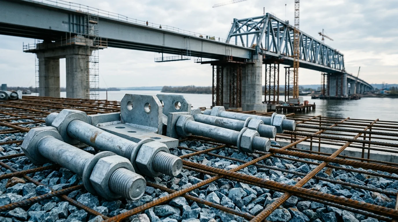
Mine Ventilation Door Hardware: Compare Materials and Coatings for Air Leakage Control
For low (<1kPa), medium (1-3kPa), and high (>3kPa) air pressure roadways, choose between 304 stainless steel, Q235B hot-dip galvanized, and Inconel 625 hardware. Each plan addresses hinge seizure, seal aging, and corrosion in humid/dusty environments. Includes inspection intervals and replacement criteria
RISK AUDIT // ENGINEERING DIAGNOSIS
Procurement Pitfall Avoidance Guide
"Real failures from real mines: rust-seized locks, dust-worn hinges, and cracked seals."
QC-AUDIT // REV.5
SCALE 1:1 · 03 ITEMS
RISK-01
Ventilation Door Mechanical Lock Long-Term Inaction Leading to Rust Seizure
Corrective Measures
RISK-02
Hinge Dust Accumulation and Wear Leading to Seal Failure and Air Leakage
Corrective Measures
RISK-03
Seal Aging and Brittle Cracking Leading to Positive Pressure Leakage
Corrective Measures
FIELD-SPECIFIC INSIGHT
Key Differences in Ventilation Door Hardware Plans
The three hardware plans differ in hinge load capacity, seal material, and corrosion protection. The choice depends on air pressure, humidity, and required service life. Below are the critical checkpoints for procurement and maintenance
WHAT TO CHECK
- 1Hinge load capacity: Plan A ≥200kg (304 SS), Plan B ≥500kg (Q235B forged), Plan C ≥1000kg (Inconel 625). Under-spec hinges cause seal gap and air leakage
- 2Seal material: EPDM (Plan A) suitable for -40~120°C; FKM (Plan B) acid-resistant up to 200°C; ceramic composite (Plan C) for >3kPa and high temperature. Wrong seal leads to cracking and leakage
- 3Corrosion protection: Plan A uses 304 SS (C3 standard); Plan C uses Inconel 625 (C5-M). Inadequate coating causes rust seizure of lock linkage
- 4Lock mechanism: Mechanical linkage (Plan A) may seize without operation; hydraulic (Plan B) and pneumatic (Plan C) offer faster response. Emergency door failure risk if lock seizes
- 5Maintenance cycle: All plans require inspection every 6 months; full replacement every 5 years (Plan A) to 15-20 years (Plan C). Skipping inspection leads to seal compression loss and energy waste
| Check | Why it matters | What to specify |
|---|---|---|
| Hinge load capacity vs door weight | Under-rated hinge leads to sagging, seal gap, and air leakage | Specify hinge load capacity ≥ door weight × safety factor (e. G. , 1.5) |
| Seal material temperature range | FKM resists up to 200°C | Specify seal material and temperature range per mine environment |
| Corrosion protection level | Inadequate coating causes hinge/lock seizure in humid/dusty conditions | Specify coating standard (e. G |
| Lock mechanism type and response time | Mechanical linkage may seize if not operated; hydraulic/pneumatic ensures fast emergency opening | Specify lock type and response time (e. G. , <2s for hydraulic) |
| Inspection and replacement schedule | Missing inspection leads to seal compression loss and increased leakage | Specify inspection interval (e. G. , every 6 months) and replacement cycle (e. G. , 5 years for Plan A) |
All data from page content. Verify actual mine conditions (air pressure, humidity, temperature) before selecting plan
Evidence level: source-page-only
INDUSTRY TECH REFERENCE
Interlocked Air Doors: Location, Count, and the Intactness Check
The top layer of air-door hardware is the regulation: interlocked doors on the intake/return connecting roadway have a written location, count and intactness check — everything else is where a plan can flex. Run this table item by item and clear the regulatory gate first.
| Check item | Regulatory / working requirement |
|---|---|
| Location | Intake/return connecting roadway (separates intake air from return air) |
| Forward interlocked doors | No fewer than 2 |
| Reverse doors | No fewer than 2; or 2 interlocked doors combining forward and reverse function |
| Intactness check | Routine intactness inspection |
| Failure consequence | Failed interlock → air short-circuit → no air at the face → gas accumulation |
| Hardware size standard | No dedicated product standard (limit/bracket bolt sizes = logged gap) — accept against the operator's working procedure / ventilation plan |
The location and door count follow Coal Mine Safety Regulations Article 165 (2025 edition, effective 2026-02-01): an intake/return connecting roadway must have no fewer than 2 forward interlocked doors and 2 reverse doors (or 2 interlocked doors combining both functions)[^1]; the "routine intactness inspection" and the "limit/bracket bolt size = logged gap" come from §5 scene table[^1]; on the US side, 30 CFR 75.370 ventilation-plan approval makes the plan's sizes the purchase sizes (§4); "no uniform commercial spec, selection at working-procedure level" follows §4[^19][^20]. Only public regulation clauses and standard numbers are quoted; no product-standard table data is reproduced.
INDUSTRY TECH REFERENCE
A Seized Door Lock: How the Airflow Short-Circuits, Step by Step
Two doors rely on an interlock linkage to keep at least one closed — when the interlock seizes, the harm is not just an unopenable door but a short-circuited airflow. Follow the chain in this order, and run the daily check in the same order.
- 1The interlock linkage / limit parts sit unused for long stretches — in a damp, dusty roadway, mechanical interlock parts can go un-operated for months and their rubbing faces start to corrode and stick
- 2Metal parts corrode and bind — the underground corrosion-management baseline is zinc or tin plating on bolts, nuts and washers (explosion-proof electrical requirement); once the coating breaks, binding worsens
- 3One door jams in the open position — both doors now form a through passage and the intake/return airflow short-circuits
- 4Air short-circuit → effective air at the face drops → gas dilution fails → accumulation, a ventilation safety event
- 5Defense: routine intactness inspection plus test open/close on the operator's working-procedure cadence (no uniform spec); on the ground, a door's state shifts the whole-mine operating point in real time and VOD systems get deliberately damaged — reliability comes from daily management, not a one-time install
The mechanism and consequence chain (failed interlock → air short-circuit → no air at the face → gas accumulation) follows §2 FM-7, consistent with the interlock logic of Coal Mine Safety Regulations §165[^1]; the underground metal corrosion-management baseline (zinc/tin-plated bolts, nuts, washers, per the explosion-proof electrical requirement) and "door opening/closing makes pressure pulses" follow §1[^21][^11]; "a door's state changes the whole-mine operating point in real time, VOD gets deliberately damaged, ventilation technicians/engineers are overworked" is a first-line Reddit community source (medium confidence)[^22]; "routine intactness inspection" and "no uniform spec — selection at working-procedure level" follow §5/§4[^19][^20]. No interlock sizes or torque are given (none published — logged gap).
INDUSTRY TECH REFERENCE
Air-Door Hardware Acceptance: No Dedicated Standard, So Follow the Working Procedure
An air door is a ventilation facility and its hardware is the subordinate part — the acceptance basis is usually not a product standard but the operator's working procedure and ventilation plan. These four points set the boundary and the basis.
- In scope: door bracket and limit pieces, interlock/hinge connecting parts, and supporting bolts — this sits inside the all-category high-strength fastener boundary
- Out of scope: the door leaf is not a fastener — an explosion-proof/ventilation door leaf is a structural and non-metallic part, so do not quote it as hardware
- No published dedicated sizes: the limit-switch bracket bolt sizes have no external evidence (logged gap) — there is no "standard industry size" to copy; list the duty and fixing points per the operator's working procedure
- Acceptance basis: US 30 CFR 75.370 requires the ventilation plan to be approved, and the sizes in the plan become the purchase sizes; on the Chinese side, selection sits at the working-procedure level with no uniform commercial spec sheet
The supply boundary — in scope for door bracket and limit pieces, out of scope for the door leaf — follows §5[^1]; the limit/bracket bolt size gap follows §2 FM-7[^1]; US regulation-as-specification (30 CFR 75.370 ventilation-plan approval) and Chinese working-procedure-level selection follow §4[^10][^19][^20]. No bolt sizes or torque are given (none published — logged gap).
INDUSTRY TECH REFERENCE
Size Door Pressure from the Fan Operating Point First
The differential across an air door is not a tier you pick casually — it is set by the ventilation system's actual operating condition at that location. Attach the fan operating point to the RFQ.
Mainstream development contra-rotating fans (No. 5.6–7.1, 2×11–2×45 kW) deliver roughly 400–6700 Pa total pressure; the full FBD line (22 sizes) spans 172–8600 Pa; with large sets feeding long runs, duct static pressure can reach 5000–8000 Pa. The differential across a door cannot exceed the total pressure its system can supply (order-of-magnitude), and it floats with the main-fan duty and door opening/closing. Do not just write "low/medium/high pressure" — attach the fan model and operating point, the delivery-line length and the number of bends, and let the supplier size against the real system.
The pressure figures follow §1 (positive-pressure spectrum)[^11][^2]: mainstream development fans (No. 5.6–7.1) roughly 400–6700 Pa, the full 22-size FBD line 172–8600 Pa, and large-set long-line duct static pressure 5000–8000 Pa (the revised value superseding the L1 draft's 1000–3000 Pa). "Door differential ≤ system total pressure" is an **order-of-magnitude estimate** (scene-level inference, not a measured or regulatory value, flagged as such in the body); the <1 kPa / 1–3 kPa / >3 kPa tiering has no direct KB basis and is not moved in as a stated fact — use it only as a reference scale for on-site sizing.
INDUSTRY TECH REFERENCE
Air-Door Hardware Reliability: Half Lives in the Maintenance Organization
Installing the hardware is only the start — this trade is carried by the day-to-day execution of the ventilation-response organization. Align on these four and stop betting reliability on a one-time install.
- Subordinate role: an interlock failure is essentially a "facility failure" and the fastener is only one link — right hardware does not guarantee a reliable interlock
- Intactness-check cadence: doors on the intake/return connecting roadway get a routine intactness inspection (scene-table requirement), and the same underground maintenance system calls for daily checks of joint clamps, seal soundness and joint looseness — write this inspection cadence into the O&M agreement
- Ground reality: door opening/closing and equipment moving in the ramp change the whole-mine operating point in real time; VOD (ventilation-on-demand) systems get deliberately damaged — the field crew's execution and inspection discipline decide whether the hardware actually works
- RFQ actions: write the operating frequency (daily open/close cycles), the inspection/test cadence and the corrosion-environment class into the inquiry and the O&M agreement; selection has no uniform spec and is set by the operator's working procedure — align to the actual site, which beats copying another mine's list
The "subordinate-part" role and failure consequences follow §2 FM-7[^1]; the "routine intactness inspection" follows §5 scene table[^1]; the "daily checks of joint clamps, tape seals and joint looseness" reflect a duct manufacturer's maintenance guide[^21], cited here as the same underground maintenance discipline; "a door's state changes the operating point in real time, VOD gets damaged, ventilation technicians/engineers are overworked" is a Reddit community source (medium confidence)[^22]; "no uniform spec, selection at working-procedure level" follows §4[^19][^20].
PLAN COMPARISON
Three-Plan Core Parameter Comparison
Compare row by row. Click column headers to jump to plan details.
| A · Plan A · 304 Stainless Steel Standard Ventilation Door Hardware | B · Plan B · Q235B Heavy-Duty Ventilation Door Hardware | C · Plan C · Special Alloy Extreme Ventilation Door Hardware | |
|---|---|---|---|
| 1. HEAVY-DUTY HINGE | |||
| SPEC | Load Capacity ≥200kg, 304 Stainless Steel Precision Casting | Load Capacity ≥500kg, Q235B Forged + Hot-Dip Galvanized | Load Capacity ≥1000kg, Inconel 625 Forged |
| MATERIAL | 304 Stainless Steel | Q235B | — |
| FINISH | hot-dip galvanized ≥55 μm per ISO 1461 | HDG >=55um per ISO 1461 | HDG >=55um per ISO 1461 |
| 2. MECHANICAL LOCK | |||
| SPEC | Linkage Interlock, Q235B Hot-Dip Galvanized | Dual Cylinder Synchronous Interlock, Response Time <2s | PLC Control + Position Sensor, Automatic Interlock |
| MATERIAL | Q235B | — | — |
| FINISH | HDG >=55um per ISO 1461 | HDG >=55um per ISO 1461 | HDG >=55um per ISO 1461 |
| 3. SEAL STRIP | |||
| SPEC | D-Shape Cross Section, Shore Hardness 60A, Temperature Resistance -40~120°C | P-Shape Cross Section, FKM Material Acid Resistant Temperature 200°C | Al2O3 Ceramic Core + FFKM Cladding, Pressure Resistance 10kPa |
| MATERIAL | EPDM Rubber | EPDM Rubber | EPDM Rubber |
| GRADE | Shore Hardness 60A | — | — |
| FINISH | HDG >=55um per ISO 1461 | HDG >=55um per ISO 1461 | HDG >=55um per ISO 1461 |
| 4. FIXING BOLT | |||
| SPEC | M12-M16, A2-70 Stainless Steel Anti-Seize | M16-M20, Grade 10.9 Dacromet Coated | RFID Chip, Records Switching Cycles and Maintenance Records |
| MATERIAL | 70 Stainless Steel | — | EPDM Rubber |
| GRADE | A2-70 | Grade 10.9 | — |
| FINISH | HDG >=55um per ISO 1461 | HDG >=55um per ISO 1461 | HDG >=55um per ISO 1461 |
| 5. GREASE | |||
| SPEC | Lithium Grease NLGI-2, Apply to Hinge Pin Anti-Seize | Epoxy Zinc-Rich Primer + Polyurethane Topcoat, Salt Spray Resistance 500h | Special Tensioner, Preload Controllable ±3% |
| MATERIAL | — | Polyurethane | — |
| FINISH | HDG >=55um per ISO 1461 | HDG >=55um per ISO 1461 | HDG >=55um per ISO 1461 |
Plan A · 304 Stainless Steel Standard Ventilation Door Hardware
C3 per ISO 12944-2 for low-pressure dry roadways
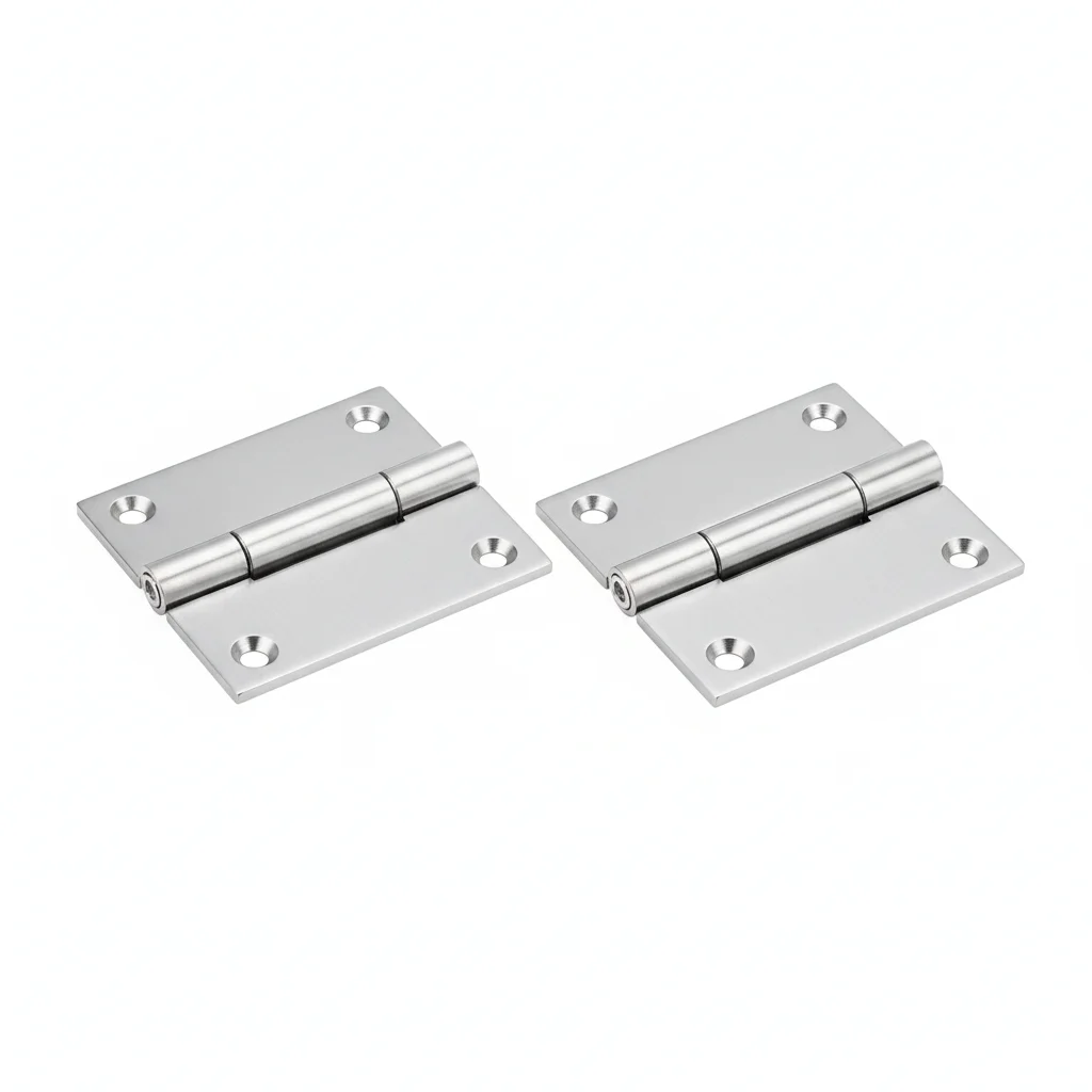
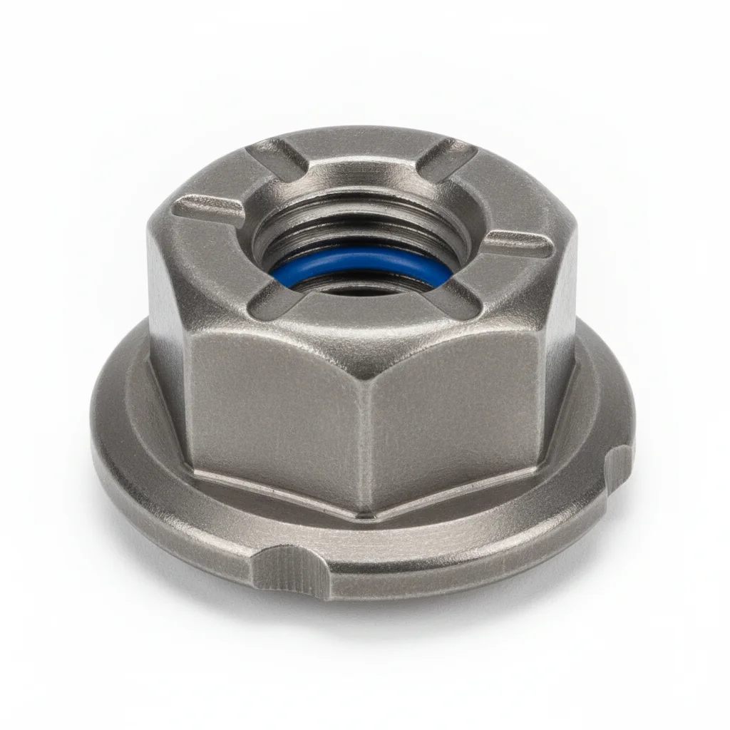
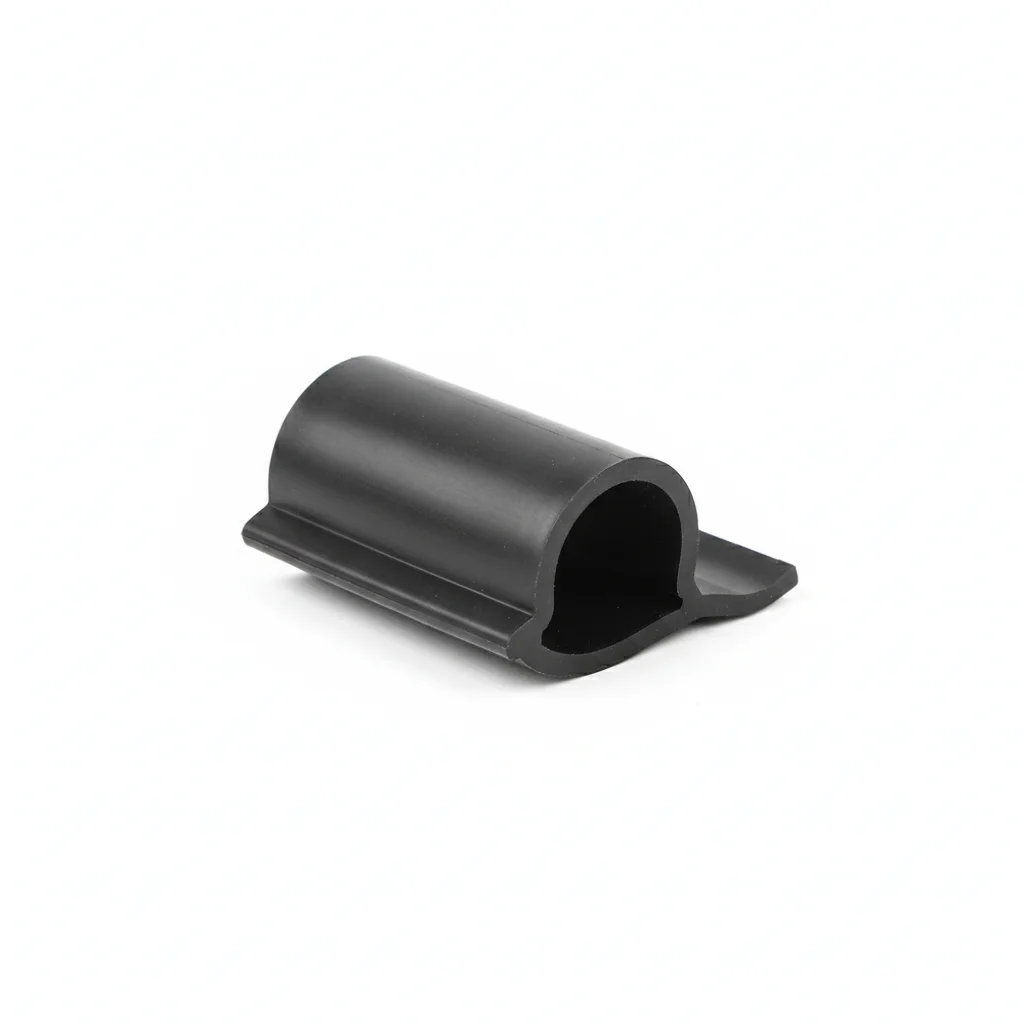
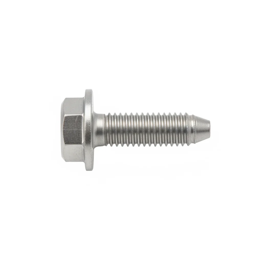
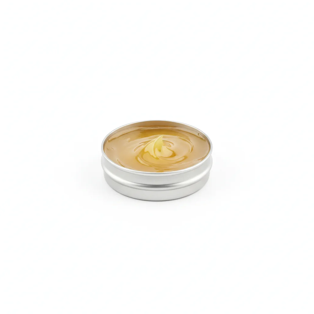
| Heavy-Duty Hinge | Mechanical Lock | Seal Strip | Fixing Bolt | Grease | |
|---|---|---|---|---|---|
| SPEC | Load Capacity ≥200kg, 304 Stainless Steel Precision Casting | Linkage Interlock, Q235B Hot-Dip Galvanized | D-Shape Cross Section, Shore Hardness 60A, Temperature Resistance -40~120°C | M12-M16, A2-70 Stainless Steel Anti-Seize | Lithium Grease NLGI-2, Apply to Hinge Pin Anti-Seize |
| MATERIAL | 304 Stainless Steel | Q235B | EPDM Rubber | 70 Stainless Steel | — |
| GRADE | — | — | Shore Hardness 60A | A2-70 | — |
| FINISH | hot-dip galvanized ≥55 μm per ISO 1461 | HDG >=55um per ISO 1461 | HDG >=55um per ISO 1461 | HDG >=55um per ISO 1461 | HDG >=55um per ISO 1461 |
| CORROSION | C3 (ISO 12944-2) | C3 (ISO 12944-2) | Not applicable (polymer) | C3 (ISO 12944-2) | C3 (ISO 12944-2) |
| TEMP | -20°C to +80°C | -20°C to +80°C | -20°C to +80°C | -20°C to +80°C | -20°C to +80°C |
| WEIGHT | ~0.5 kg/piece | ~0.5 kg/piece | ~0.5 kg/piece | ~0.5 kg/piece | ~0.5 kg/piece |
| MOQ | 100 pcs | 100 pcs | 100 pcs | 100 pcs | 100 pcs |
| PACK | VCI paper + carton | VCI paper + carton | VCI paper + carton | VCI paper + carton | VCI paper + carton |
| STD | ISO 898-1, GB/T 3098.1 | ISO 898-1, GB/T 3098.1 | ISO 898-1, GB/T 3098.1 | ISO 898-1, GB/T 3098.1 | ISO 898-1, GB/T 3098.1 |
| USE | 304 Stainless Steel Precision Casting | Q235B Hot-Dip Galvanized | Temperature Resistance -40~120°C | A2-70 Stainless Steel Anti-Seize | Apply to Hinge Pin Anti-Seize |
PROCEDURE
- Align hinge leaves with door frame, ensuring hinge pins are plumb and door swing is free before tightening.
- Drill pilot holes for M12-M16 A2-70 bolts using a template to maintain 0.5mm alignment tolerance.
- Apply lithium grease NLGI-2 to hinge pins and threads to prevent galling during assembly.
- Torque bolts in a star pattern to spec using a calibrated wrench, verifying with a torque seal.
- Compress EPDM seal strip to 20-30% of its original height when closing the door, checking for uniform contact.
- Cycle the door 10 times to confirm smooth operation and seal integrity before final acceptance.
COMMON ERRORS
| ✕ WRONG | CONSEQUENCE | ✓ CORRECT |
|---|---|---|
| Using ungalvanized carbon steel bolts instead of A2-70 stainless | Rust streaks stain the door and hinge seizure occurs within months in humid air. | Verify A2-70 grade marking and use anti-seize on threads. |
| Overtightening hinge bolts, distorting the frame | Seal gap appears on the opposite side, increasing air leakage. | Follow the specified torque sequence and check door perimeter gap with a feeler gauge. |
MAINTENANCE
Inspect hinges, locks, and seals at each scheduled ventilation survey; re-torque any hinge bolts that have loosened, replace EPDM seals showing compression set above 35%, and lubricate hinge pins with NLGI-2 grease seasonally.
Plan B · Q235B Heavy-Duty Ventilation Door Hardware
C4 Harsh per ISO 12944-2
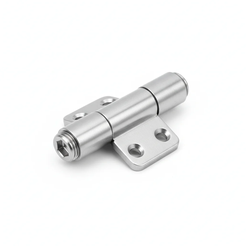
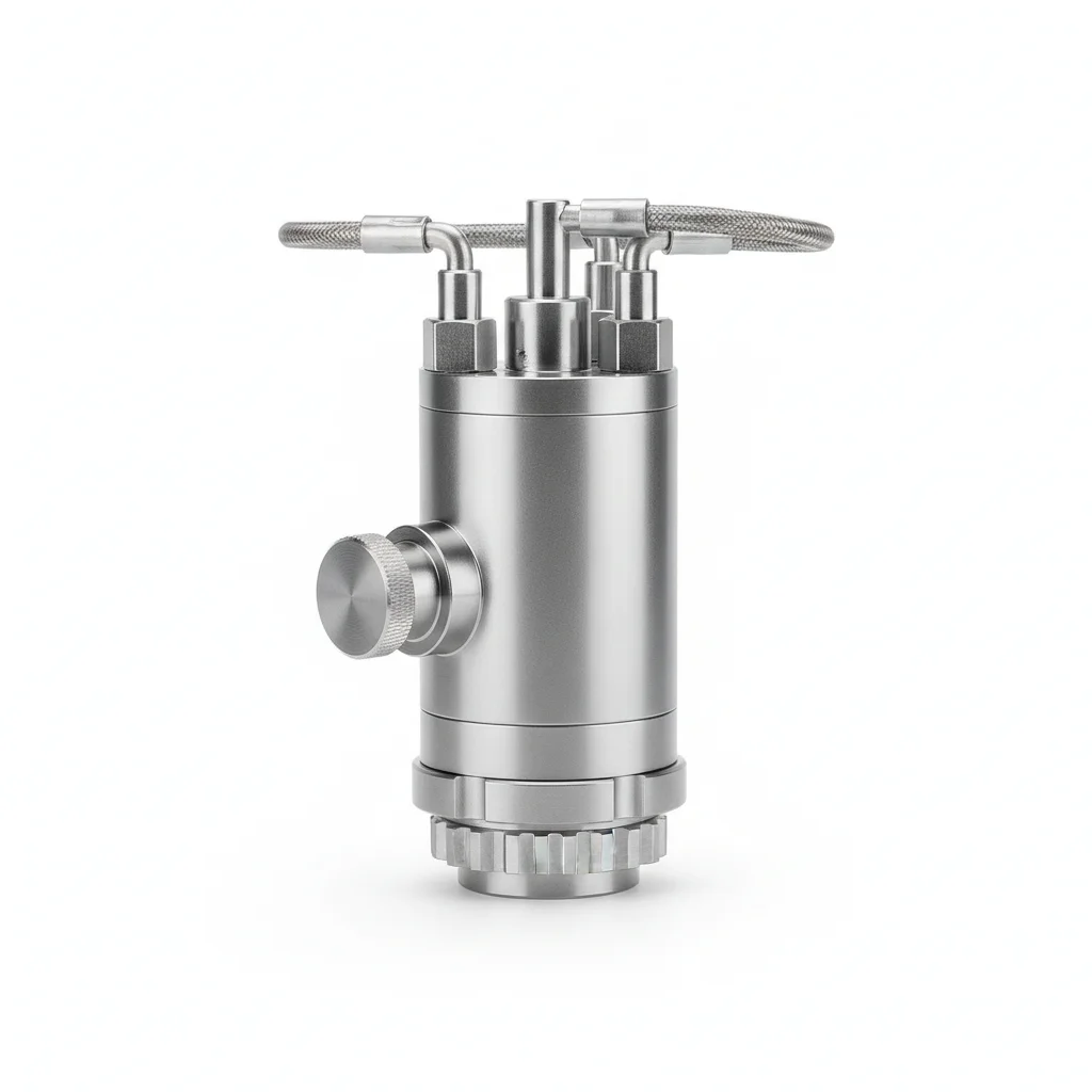
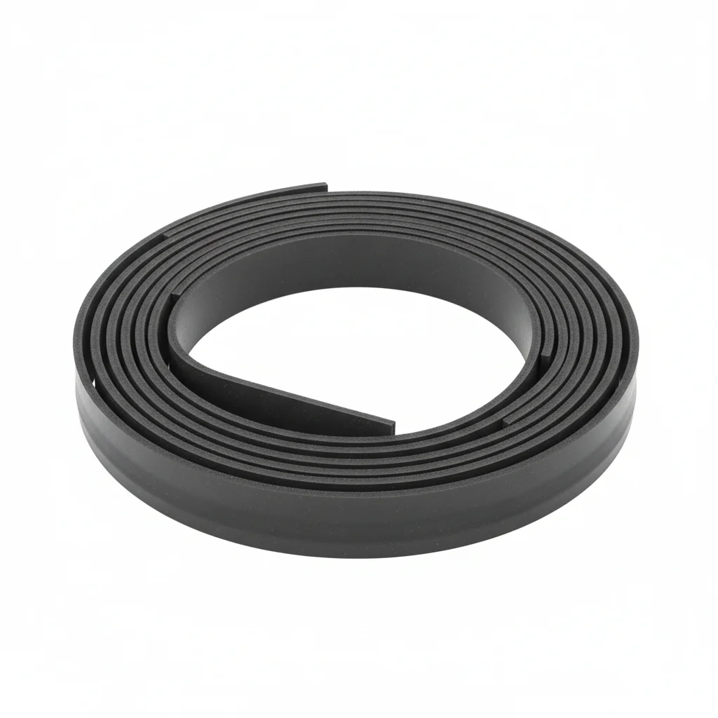
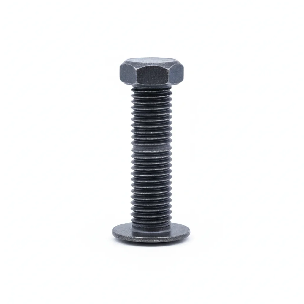
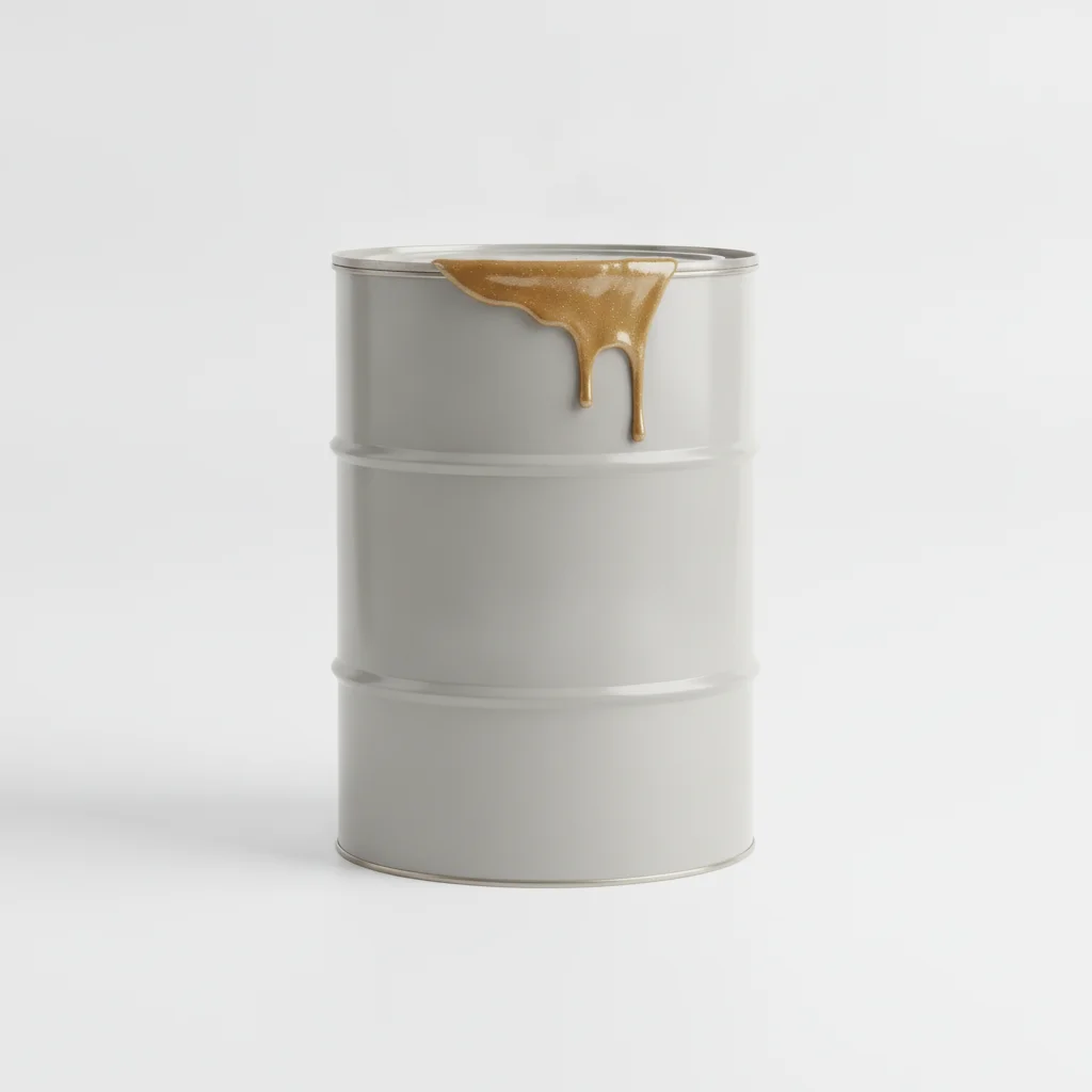
| Reinforced Hinge | Hydraulic Lock Device | Fluoro Rubber Seal Strip | High-Strength Fixing Bolt | Anti-Corrosion Coating | |
|---|---|---|---|---|---|
| SPEC | Load Capacity ≥500kg, Q235B Forged + Hot-Dip Galvanized | Dual Cylinder Synchronous Interlock, Response Time <2s | P-Shape Cross Section, FKM Material Acid Resistant Temperature 200°C | M16-M20, Grade 10.9 Dacromet Coated | Epoxy Zinc-Rich Primer + Polyurethane Topcoat, Salt Spray Resistance 500h |
| MATERIAL | Q235B | — | EPDM Rubber | — | Polyurethane |
| GRADE | — | — | — | Grade 10.9 | — |
| FINISH | HDG >=55um per ISO 1461 | HDG >=55um per ISO 1461 | HDG >=55um per ISO 1461 | HDG >=55um per ISO 1461 | HDG >=55um per ISO 1461 |
| CORROSION | C3 (ISO 12944-2) | C3 (ISO 12944-2) | Not applicable (polymer) | C3 (ISO 12944-2) | C3 (ISO 12944-2) |
| TEMP | -20°C to +80°C | -20°C to +80°C | -20°C to +80°C | -20°C to +80°C | -20°C to +80°C |
| WEIGHT | ~0.5 kg/piece | ~0.5 kg/piece | ~0.5 kg/piece | ~0.5 kg/piece | ~0.5 kg/piece |
| MOQ | 100 pcs | 100 pcs | 100 pcs | 100 pcs | 100 pcs |
| PACK | VCI paper + carton | VCI paper + carton | VCI paper + carton | VCI paper + carton | VCI paper + carton |
| STD | ISO 898-1, GB/T 3098.1 | ISO 898-1, GB/T 3098.1 | ISO 898-1, GB/T 3098.1 | ISO 898-1, GB/T 3098.1 | ISO 898-1, GB/T 3098.1 |
| USE | Q235B Forged + Hot-Dip Galvanized | Response Time <2s | FKM Material Acid Resistant Temperature 200°C | Grade 10.9 Dacromet Coated | Salt Spray Resistance 500h |
PROCEDURE
- Degrease the hinge mounting faces with acetone to remove any oily film, then check that surface roughness stays below Ra 3.2 µm as required for the Q235B forged substrate.
- Coat the contact areas with the epoxy zinc-rich primer from the anti-corrosion coating kit, and fit PTFE-coated washers under the heads of the Grade 10.9 M16-M20 Dacromet bolts.
- Position the reinforced hinge (load capacity ≥500 kg) and hydraulic lock device, then tighten the bolts in a crisscross sequence to the torque specified for Grade 10.9 fasteners, logging ambient humidity and temperature.
- Pull-test a 5% random sample of the installed bolts to 80% of proof load; replace any bolt that slips or shows permanent elongation.
- Apply the polyurethane topcoat over the bolt heads and hinge edges to seal the assembly, and attach a corrosion monitoring coupon next to the hinge for future checks.
COMMON ERRORS
| ✕ WRONG | CONSEQUENCE | ✓ CORRECT |
|---|---|---|
| Using ordinary Q235B bolts instead of the specified Grade 10.9 Dacromet-coated fasteners | In a 1-3 kPa humid roadway, the lower-grade bolts corrode and loosen, letting the reinforced hinge sag and the fluoro rubber seal lose compression, which raises air leakage. | Verify each bolt carries the Grade 10.9 marking and a Dacromet coating before installation; reject any unmarked or damaged fasteners. |
| Mounting the hydraulic lock without checking its response time | A slow-acting lock (over 2 s) can leave both doors open during a pressure surge, causing a short-circuit airflow that disrupts ventilation balance. | After installation, actuate the hydraulic lock and confirm it responds in under 2 s as specified; adjust hydraulic pressure if slower. |
MAINTENANCE
Inspect the hinge pins, lock linkage, and fluoro rubber seal at least seasonally and after any pressure event exceeding 3 kPa; re-torque any Grade 10.9 bolt that has lost more than 15% of its initial clamp load, and replace seals showing cracks or permanent set beyond 35%.
Plan C · Special Alloy Extreme Ventilation Door Hardware
C5-M Extreme per ISO 12944-2
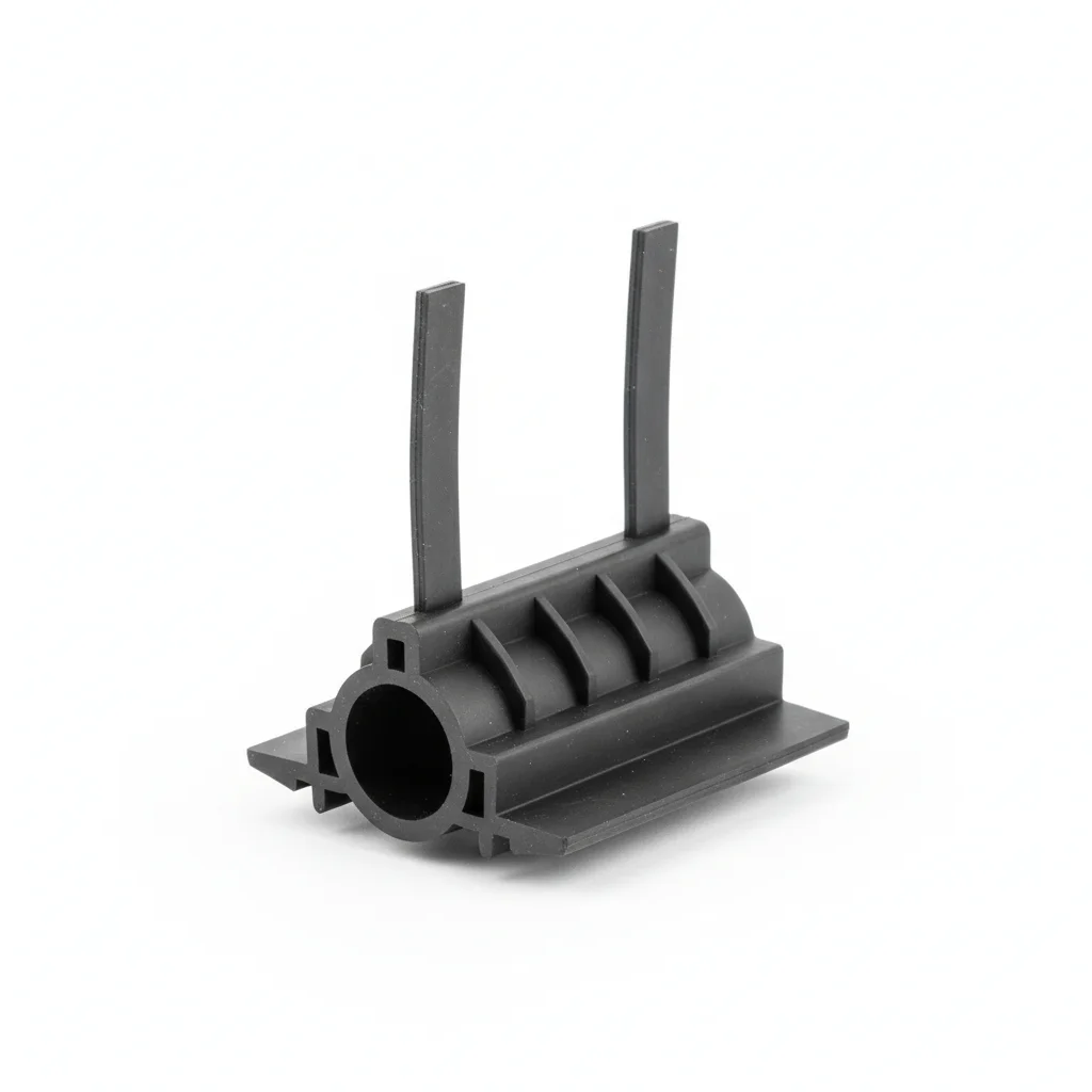
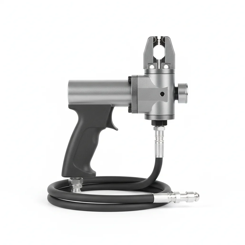
| Special Alloy Hinge | Pneumatic Lock System | Ceramic Composite Seal Strip | Smart Monitoring Tag | Hydraulic Installation Tooling | |
|---|---|---|---|---|---|
| SPEC | Load Capacity ≥1000kg, Inconel 625 Forged | PLC Control + Position Sensor, Automatic Interlock | Al2O3 Ceramic Core + FFKM Cladding, Pressure Resistance 10kPa | RFID Chip, Records Switching Cycles and Maintenance Records | Special Tensioner, Preload Controllable ±3% |
| MATERIAL | — | — | EPDM Rubber | EPDM Rubber | — |
| GRADE | — | — | — | — | — |
| FINISH | HDG >=55um per ISO 1461 | HDG >=55um per ISO 1461 | HDG >=55um per ISO 1461 | HDG >=55um per ISO 1461 | HDG >=55um per ISO 1461 |
| CORROSION | C3 (ISO 12944-2) | C3 (ISO 12944-2) | Not applicable (polymer) | Not applicable (polymer) | C3 (ISO 12944-2) |
| TEMP | -20°C to +80°C | -20°C to +80°C | -20°C to +80°C | -20°C to +80°C | -20°C to +80°C |
| WEIGHT | ~0.5 kg/piece | ~0.5 kg/piece | ~0.5 kg/piece | ~0.5 kg/piece | ~0.5 kg/piece |
| MOQ | 100 pcs | 100 pcs | 100 pcs | 100 pcs | 100 pcs |
| PACK | VCI paper + carton | VCI paper + carton | VCI paper + carton | VCI paper + carton | VCI paper + carton |
| STD | ISO 898-1, GB/T 3098.1 | ISO 898-1, GB/T 3098.1 | ISO 898-1, GB/T 3098.1 | ISO 898-1, GB/T 3098.1 | ISO 898-1, GB/T 3098.1 |
| USE | Inconel 625 Forged | Automatic Interlock | Pressure Resistance 10kPa | Records Switching Cycles and Maintenance Records | Preload Controllable ±3% |
PROCEDURE
- Clean the Inconel 625 hinge mounting faces with MEK to remove all organic residue, and verify surface roughness is below Ra 1.6 µm for a tight metal-to-metal joint.
- Apply a marine-grade anti-corrosion compound rated for -50°C to 200°C to the contact faces, and place PTFE-encapsulated washers under the fasteners to prevent galvanic corrosion.
- Align the special alloy hinge (load capacity ≥1000 kg) and pneumatic lock system within 0.3 mm, then tension the bolts using the hydraulic tensioner to achieve the preload within ±3% as specified.
- Perform positive material identification (PMI) on a 10% sample of the Inconel 625 components to confirm alloy composition, and record results for the compliance audit.
- Apply a protective sealant over the bolt heads and hinge edges, then install the smart monitoring tag (RFID) to record switching cycles and maintenance data for future inspections.
COMMON ERRORS
| ✕ WRONG | CONSEQUENCE | ✓ CORRECT |
|---|---|---|
| Substituting 304 stainless steel bolts for the Inconel 625 fasteners | In a >3 kPa high-temperature roadway, the 304 bolts creep and relax, allowing the hinge to loosen and the ceramic composite seal to lose its 10 kPa pressure rating, risking a blowout. | Verify each fastener is marked as Inconel 625 and confirm via PMI testing before installation; reject any 304 or other alloy parts. |
| Overtightening the ceramic composite seal strip during installation | Excessive compression cracks the Al2O3 ceramic core, destroying the seal's integrity and causing immediate leakage under high pressure. | Follow the specified compression limit for the ceramic composite strip; use a torque wrench or feeler gauge to ensure the seal is compressed to the designed gap, not beyond. |
MAINTENANCE
Inspect the Inconel 625 hinge, pneumatic lock, and ceramic composite seal at each overhaul window or after any thermal excursion above 600°C; verify the RFID tag records match the actual switching cycles, and replace the seal if its compression set exceeds the 10% limit specified for the ceramic composite material.
SELECTION GUIDE
How to Choose Ventilation Door Hardware Plan Based on Air Pressure Level?
| Operating condition | Recommended option | Key basis |
|---|---|---|
| Low air pressure roadway (<1 kPa), dry, low-corrosion | Plan A: 304 SS heavy-duty hinge (load ≥200kg) + mechanical linkage interlock (Q235B hot-dip galvanized) + EPDM D-section seal (Shore 60A, -40~120°C) + A2-70 anti-seize fixing bolts (M12-M16) | C3 per ISO 12944-2; EPDM rated -40~120°C suits low-pressure dry roadways; lowest cost |
| Medium air pressure (1-3 kPa), humid corrosive environment | Plan B: Q235B forged reinforced hinge (load ≥500kg) + dual-cylinder hydraulic interlock (response <2s) + FKM fluoro rubber seal (acid-resistant, 200°C) + Grade 10.9 Dacromet bolts (M16-M20) | C4 harsh per ISO 12944-2; FKM resists acids to 200°C; pressure capacity 50% higher than standard parts |
| High air pressure (>3 kPa) or high temperature, ultra-long life | Plan C: Inconel 625 special-alloy hinge (load ≥1000kg) + PLC pneumatic auto-interlock + ceramic composite seal (Al2O3 core + FFKM cladding, withstands 10kPa) | C5-M extreme per ISO 12944-2; Inconel 625 resists 600°C+; ceramic composite withstands up to 10kPa |
| Lock mechanism choice and emergency-opening risk | Low operation frequency uses mechanical linkage (Plan A); fast response needs hydraulic <2s (Plan B) or pneumatic PLC (Plan C); conduct monthly manual test open/close | Mechanical linkage can seize in long idle humid/dusty conditions; monthly test even without passage prevents hinge rust seizure |
| Maintenance and replacement schedule | Inspect all plans every 6 months; full replacement every 5 years (Plan A) up to 15-20 years (Plan C) | Skipping inspection leads to seal compression loss and increased air leakage |
REFERENCED STANDARDS
Technical Basis and Reference Standards
General Test Methods and Judgment Rules for Flame Retardant and Antistatic Safety Performance of Polymer Products for Coal Mines
Coal Mine Ventilation Safety Monitoring SystemSafety Marking for Mining Products
Mine Ventilation DoorVentilation Door for Coal Mines
Coal Mine Pit BottomIndustrial Fans - Performance Testing Using Standardized Airways
Mine Ventilation TerminologyStandard Specification for Chromium and Chromium-Nickel Stainless Steel Plate, Sheet, and Strip (304 Material Standard)
SUPPLIER CAPABILITY
Quality, Delivery & Customization
Quality Control
- ✓MTC material certificates with every batch
- ✓Key parts sampled for hardness/salt spray/torque coefficient
- ✓100% inspection or AQL sampling before shipment
Delivery
- ✓Standard parts made to order: 7-15 days
- ✓Custom parts: 25-45 days
- ✓FOB/CIF/DDP supported
Customization
- ✓Drawing review and material matching
- ✓Non-standard sizes/heads/threads
- ✓Small-batch prototyping supported
Certification
- ✓Material certificates (MTC)
- ✓Spectrographic analysis reports
- ✓Salt spray test reports (on request)
MOQ: No MOQ for standard parts; custom parts assessed by process complexity
FAQ
Frequently Asked Questions
RELATED READING
Keep Reading & Next Step
NEXT: SELECTION & RFQ
Ventilation Duct HangersFollow this page's selection path to the same-scenario RFQ page.
RELATED TOPIC
Ventilation Duct HangersRELATED TOPIC
Ventilation DuctsBEYOND TECHNICAL SPECS
Finding the right factory, controlling quality, delivering on time — that's the real challenge. We cover fasteners, rubber, plastics, industrial textiles. One team, end to end.
SEE CAPABILITIES →