Outdoor Cable Clamp: Preventing Cable Detachment Under Wind Vibration
Outdoor cable clamp application covers three typical runs: street-lighting feeders, industrial-park cable trays, and substation outgoing cable racks; selection is driven by wind vibration, UV and salt-spray exposure. Based on IEC 61914, compare clamping force retention of nylon, PVC, and stainless steel clamps. Address risks of insufficient clamping force leading to cable slip, rust in acid rain, and improper spacing causing sag and wear
RISK AUDIT // ENGINEERING DIAGNOSIS
Procurement Pitfall Guide
"Common failure modes seen in municipal lighting maintenance logs"
QC-AUDIT // REV.5
SCALE 1:1 · 03 ITEMS
RISK-01
Insufficient cable clamping force leads to cable detachment during wind vibration
Corrective Measures
RISK-02
Metal cable clamps rust and loosen in acid rain environments
Corrective Measures
RISK-03
Improper cable clamp installation spacing leads to cable sagging and wear
Corrective Measures
FIELD-SPECIFIC INSIGHT
Cable Clamp Failure Chain: What to Specify in Your RFQ
In outdoor landscape lighting, cable clamps must resist wind vibration, corrosion, and mechanical wear. The most overlooked parameter is clamping force retention after thermal cycling and UV exposure. Specify material, clamping force, and spacing to avoid cable detachment and short circuits
WHAT TO CHECK
- 1Clamping force below rating leads to cable slip after vibration cycles in wind gusts; specify minimum retention after UV aging
- 2Galvanized iron clamps in acid rain lose coating quickly; use 304 stainless steel for C3-C4 environments
- 3Vertical cable clamp spacing exceeding limit causes cable sag, leading to insulation wear; specify spacing per IEC 60364-5-52
- 4Nylon clamps degrade under UV; for outdoor use, specify UV-stabilized nylon or stainless steel with EPDM bushing
| Check | Why it matters | What to specify |
|---|---|---|
| Clamping force rating | Insufficient force causes cable slip under wind vibration, leading to short circuits | Minimum clamping force after UV exposure per IEC 61914 |
| Material corrosion resistance | Rust reduces clamp thickness and clamping force, and abrades cable insulation | 304 stainless steel for C3-C4; 316L for marine C5-M |
| Installation spacing | Excessive spacing causes cable sag and wear against pole inner wall | Vertical spacing per IEC 60364-5-52; use rubber bushing at contact points |
| UV and temperature resistance | Nylon and PVC degrade under UV, reducing clamping force and causing brittleness | UV-stabilized nylon or stainless steel |
Data based on page content: wind pressure, pole height, sway, cycles, pH, span, sag, wear rate. Verify with project-specific conditions
Evidence level: source-page-only
INDUSTRY TECH REFERENCE
The Nylon-Tie UV Chain: Cable Detaches in Wind After 2-3 Years
Why nylon ties are not a shortcut for the cable runs outside a light pole: it is not a case of "re-tie it when loose" — embrittlement has a defined 2-3 year window, and the failure shows up directly as wind-driven cable detachment.
- 1Nylon ties misapplied to the pole's external cable runs: under full-sun UV and thermal cycling the polymer chains break, and the cross-verified figure in the archive is a 2-3 year window to embrittlement
- 2Once embrittled, the tie loses elasticity and clamping force — it no longer holds the cable, it merely rests on it; and the cable's own weight (4-8 kg on an 8 m pole) is a permanent downward load
- 3In gusts the cable vibrates; with clamping force below what is required, the cable sheds and hangs or flails outside the pole
- 4Once the detached cable's insulation is worn and rain gets in — the same route as water entering the pole: cable soaking leads to leakage and a whole-circuit trip
- 5Interception points: outside the pole use 304 ties with EPDM liners (1 m horizontal / 1.5 m vertical spacing); inside the pole use 304 spring clips every 1.5 m, never nylon ties — pole interiors reach 60°C+ in summer and creep loosens them
The 2-3 year nylon UV embrittlement window and the 4-8 kg cable self-weight on an 8 m pole are magnitude estimates.
INDUSTRY TECH REFERENCE
Light-Pole Cable Fixing Ledger: Location, Part Type, and Spacing
Fixing cables on a light pole is not about one tie — it is location by location: inside the pole, external horizontal and vertical runs, and entry/exit holes each have their own part type and spacing. On poles in a coastal basic-wind-pressure band of 0.45 kN/m², wind vibration is the normal duty for cable fixing — check against the fixing ledger in the research archive.
| Location | Part type | Spacing / parameter | Constraint and failure |
|---|---|---|---|
| Vertical run inside the pole | 304 spring clip | One every 1.5 m | Nylon ties banned: pole interior reaches 60°C+ in summer, creep loosens them |
| External horizontal run | 304 tie + EPDM liner | 1 m horizontal spacing | Nylon ties embrittle in 2-3 years of UV → wind-driven detachment |
| External vertical run | 304 tie + EPDM liner | 1.5 m vertical spacing | Same as above; EPDM also isolates galvanic couples and wear |
| Cable entry/exit holes | Rubber bushing + 304 metal gland | One cable per hole | Plastic parts UV-embrittle; no plastic at exposed openings |
| Whole pole (design basis) | — | Cable self-weight 0.5-1 kg/m (4-8 kg downward pull on an 8 m pole) | Clamping sized for self-weight plus wind vibration, not just "tight enough" |
The 0.5-1 kg/m cable self-weight, the 4-8 kg downward pull on an 8 m pole and the 2-3 year nylon UV embrittlement window are magnitude estimates; the 0.45 kN/m² coastal basic wind pressure follows GB 50009-2012, Load code for the design of building structures.
INDUSTRY TECH REFERENCE
Pole Cable-Fixing Material Tiers: 304 Baseline, 316L for Salt Spray and De-Icing Salt
Material is not "higher is better" — it is matched to the pole's outdoor duty: 304 is the workhorse for general municipal and landscape poles, while coastal salt spray and de-icing salt on the ground call for 316L. The three-tier basis comes from the research archive.
- Baseline parts are 304: 304 spring clips inside the pole (one every 1.5 m) and 304 ties with EPDM liners outside — 304 covers normal outdoor atmosphere, and the EPDM interface isolates galvanic couples with galvanized flanges and aluminum housings
- When to step up to 316L: coastal salt spray and de-icing salt (Cl⁻) in ground water — the archive precedent is the in-ground luminaire face-ring bolts: 304 does not hold up under de-icing salt, so the spec goes to 316L; cable fixings follow the same boundary
- Galvanic isolation is mandatory once the material is chosen: 304 ties with EPDM liners, and EPDM gaskets at aluminum/stainless contacts — "304/316L hardware + EPDM interface" is the standard combination for pole fixings (a cross-verified figure in the archive)
- Nylon and plastic parts stay indoors: outside, UV embrittles them in 2-3 years, ending in wind-driven cable detachment; the same applies to plastic glands — exposed entry/exit holes use 304 metal glands with rubber bushings
- The material ledger: 304 is enough for general municipal poles — do not blindly upgrade to 316L for the "stainless" label; tier by the real pollution environment (salt-spray concentration, whether de-icing salt is used)
The 2-3 year nylon UV embrittlement window is a magnitude estimate.
INDUSTRY TECH REFERENCE
Standards for Pole Cables and Protection: Which One Covers Laying, IP, and Coating
The standards that govern pole cable fixing fall on five numbers — match the number first, then talk acceptance; navigation only, not a substitute for the text.
The listed standards are for navigation only, without reproducing clauses: CJJ 45 (urban road lighting design), GB 50217 (power-engineering cable design), IEC 60529 (IP code), GB 7000.1/IEC 60598 (luminaires safety) and GB/T 13912-2020 (hot-dip galvanized coatings). No magnitude-estimate figures are used.
INDUSTRY TECH REFERENCE
Supply Scope of Pole Cable Fixing: Clamps and Glands In, Light Source and Pole Out
Draw the line before you ask for quotes: what belongs on a fastener inquiry, and what does not.
On the pole cable-fixing line, fastener supply covers: 304 cable clamps/ties/spring clips, rubber bushings, 304 metal glands, junction-box bolts, EPDM liners and sealing gaskets — clamps, glands and sealants are O&M spare parts with steady repeat demand; out of scope: LED light-source modules, intelligent control systems and the pole body itself — these three do not belong on a fastener inquiry.
No magnitude-estimate figures are used.
PLAN COMPARISON
Three-Plan Core Parameter Comparison
Compare row by row. Click column headers to jump to plan details.
| A · Plan A · Economy | B · Plan B · Standard | C · Plan C · High-end | |
|---|---|---|---|
| 1. NYLON CABLE CLAMP | |||
| SPEC | Fits φ6-12mm | Fits 4-10mm² | Fits 4-10mm² |
| MATERIAL | Nylon 66 | 304 Stainless Steel | 316L Stainless Steel |
| GRADE | — | A2-70 | A4-80 |
| FINISH | HDG >=55um per ISO 1461 | HDG >=55um per ISO 1461 | HDG >=55um per ISO 1461 |
| 2. CABLE CLIP | |||
| SPEC | Fits φ4-10mm | M4×12mm | M4×12mm |
| MATERIAL | PVC + Steel Nail | 304 Stainless Steel | 316L |
| GRADE | — | A2-70 | A4-80 |
| FINISH | HDG >=55um per ISO 1461 | HDG >=55um per ISO 1461 | HDG >=55um per ISO 1461 |
| 3. PLASTIC CABLE TIE MOUNT | |||
| SPEC | M4 Screw Hole | 0.5mm thick | 0.5mm thick |
| MATERIAL | ABS Plastic | EPDM | Silicone Rubber VMQ |
| GRADE | — | — | Temp. range -60~200°C |
| FINISH | HDG >=55um per ISO 1461 | HDG >=55um per ISO 1461 | HDG >=55um per ISO 1461 |
| 4. SELF-LOCKING CABLE CLAMP | |||
| SPEC | Fits φ8-16mm | M10-M12 | M10-M12 |
| MATERIAL | PP Plastic | 304 Stainless | 304 Stainless |
| GRADE | — | A2 | A2 |
| FINISH | HDG >=55um per ISO 1461 | Passivated | Passivated |
| 5. ADHESIVE CABLE CLIP | |||
| SPEC | Fits φ5-8mm | M10-M12 | M10-M12 |
| MATERIAL | ABS + 3M Adhesive | 304 Stainless | 304 Stainless |
| GRADE | — | A2 | A2 |
| FINISH | HDG >=55um per ISO 1461 | Passivated | Passivated |
SELECTION GUIDE
Selecting the Right Clamp for Your Environment
| Operating condition | Recommended option | Key basis |
|---|---|---|
| Indoor dry environment / temporary wiring | Plan A economy: nylon 66 cable clamp (fits φ6-12mm), PVC cable clip (fits φ4-10mm), ABS plastic cable tie mount, PP self-locking cable clamp (fits φ8-16mm) | Rated C3 per ISO 12944-2; nylon/PVC/PP degrade under UV and are not recommended for long-term outdoor use — outdoor material choice per IEC 61914 |
| General outdoor environment / C3 corrosion level | Plan B standard: 304 stainless steel cable clip (A2-70, fits 4-10mm²), 304 self-tapping screw M4×12mm, EPDM rubber bushing 0.5mm, 304 flat washer | 304 stainless steel (A2-70) eliminates rust — galvanized iron with 20-30µm coating is depleted within 1-2 years at pH 4-5, clamp body thins from 1.0mm to below 0.7mm after 3 years, elastic clamping force drops over 50%; UV-stabilized nylon or stainless steel per IEC 61914 |
| Marine environment / C5-M corrosion level / extreme climate | Plan C high-end: 316L stainless steel cable clip (A4-80, fits 4-10mm²), 316L self-tapping screw M4×12mm, silicone rubber bushing VMQ (temp range -60~200°C), 304 flat washer | 316L (A4-80) provides superior chloride-induced corrosion resistance; C5-M extreme per ISO 12944-2; VMQ silicone withstands -60~200°C |
| Wind vibration areas (basic wind pressure 0.45kN/m²) | Specify rated clamping force ≥100N per GB/T 2951 with serrated clamping surface, use at least 2 cable clamps per cable with spacing ≤500mm, add anti-pull-out pressure plate at the cable outlet at the pole top | Rated clamping force below 50N lets the cable slip and detach after 10⁵ vibration cycles (about 1 year); a 10m light pole sways 5-15mm in gusts |
| Vertical installation spacing inside light pole | Control cable clamp spacing to 400-600mm (GB 50303 requires ≤1m for vertical laying; 500mm is the practical recommendation), add protective sleeves at bends and cable outlets, use rubber-lined clamps | Spacing beyond 1m makes a 12mm cable over a 1.5m span sag about 15mm; PVC insulation wears 0.1mm/year, exposing the copper core after 5-7 years |
Plan A · Economy
C3 Standard per ISO 12944-2
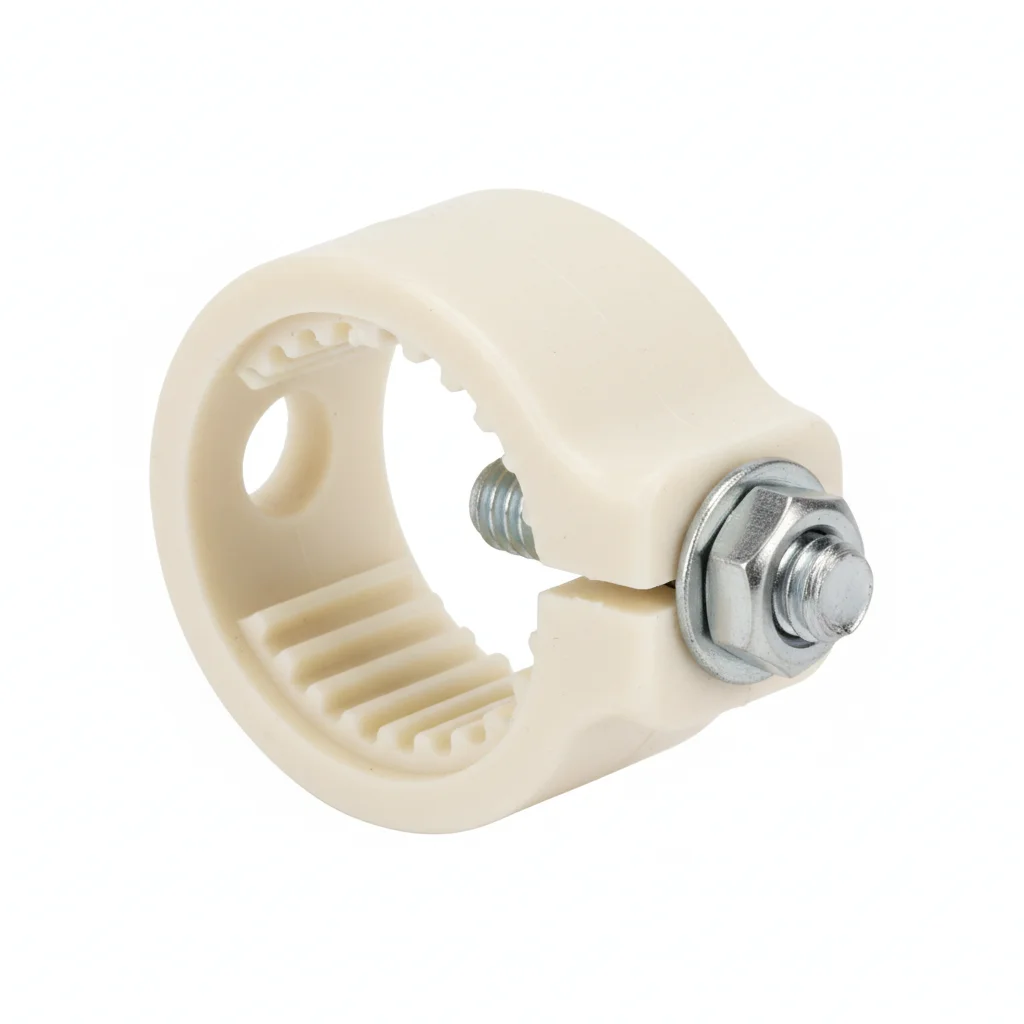
| Nylon Cable Clamp | Cable Clip | Plastic Cable Tie Mount | Self-locking Cable Clamp | Adhesive Cable Clip | |
|---|---|---|---|---|---|
| SPEC | Fits φ6-12mm | Fits φ4-10mm | M4 Screw Hole | Fits φ8-16mm | Fits φ5-8mm |
| MATERIAL | Nylon 66 | PVC + Steel Nail | ABS Plastic | PP Plastic | ABS + 3M Adhesive |
| GRADE | — | — | — | — | — |
| FINISH | HDG >=55um per ISO 1461 | HDG >=55um per ISO 1461 | HDG >=55um per ISO 1461 | HDG >=55um per ISO 1461 | HDG >=55um per ISO 1461 |
| CORROSION | C3 (ISO 12944-2) | C3 (ISO 12944-2) | C3 (ISO 12944-2) | C3 (ISO 12944-2) | C3 (ISO 12944-2) |
| TEMP | -20°C to +80°C | -20°C to +80°C | -20°C to +80°C | -20°C to +80°C | -20°C to +80°C |
| WEIGHT | ~0.5 kg/piece | ~0.5 kg/piece | ~0.5 kg/piece | ~0.5 kg/piece | ~0.5 kg/piece |
| MOQ | 100 pcs | 100 pcs | 100 pcs | 100 pcs | 100 pcs |
| PACK | VCI paper + carton | VCI paper + carton | VCI paper + carton | VCI paper + carton | VCI paper + carton |
| STD | ISO 898-1, GB/T 3098.1 | ISO 898-1, GB/T 3098.1 | ISO 898-1, GB/T 3098.1 | ISO 898-1, GB/T 3098.1 | ISO 898-1, GB/T 3098.1 |
| USE | Indoor wiring | Temporary fixing | Light-duty cables | Quick installation | No-drill installation |
PROCEDURE
- For indoor dry mounting, clean the pole interior surface with isopropyl alcohol to remove dust and oil so the nylon clamp seats firmly.
- Select a Nylon 66 clamp sized to fit the cable diameter (φ6–12mm) and position it along the vertical run, maintaining spacing ≤500mm.
- Secure the clamp by hand-tightening the locking mechanism; do not use tools that could overstress the nylon and reduce grip.
- For temporary wiring with Cable Clips (PVC + steel nail), press the nail into wood or drywall at the marked points, ensuring the cable is fully seated in the clip.
- Verify each clamp holds the cable without slippage by gently tugging along the axis; adjust spacing if any sag is visible between supports.
- Inspect the assembly for sharp edges or pinch points that could chafe the cable insulation during vibration.
COMMON ERRORS
| ✕ WRONG | CONSEQUENCE | ✓ CORRECT |
|---|---|---|
| Using a metal cable clamp in an indoor dry location where a nylon clamp would suffice | Unnecessary cost and potential galvanic corrosion at contact points with the pole interior. | Choose Nylon 66 or ABS mounts rated for indoor dry service; reserve metal clamps for outdoor exposure. |
| Overtightening a self-locking PP clamp beyond its design grip | Cable jacket deformation and reduced clamping force retention over time. | Hand-tighten only; rely on the self-locking mechanism to maintain grip. |
| Placing clamps more than 500mm apart on a vertical indoor run | Cable sag between supports leads to chafing and eventual insulation wear. | Space clamps at ≤500mm intervals as recommended for vertical runs. |
MAINTENANCE
Seasonally inspect indoor clamps for looseness or cable slip; re-seat any clamp that has moved. Replace nylon clamps showing cracking or loss of grip. No corrosion checks needed in dry indoor use.
Plan B · Standard
C3 (ISO 12944-2) for general outdoor use; 304 stainless steel (A2-70) resists acid rain corrosion.
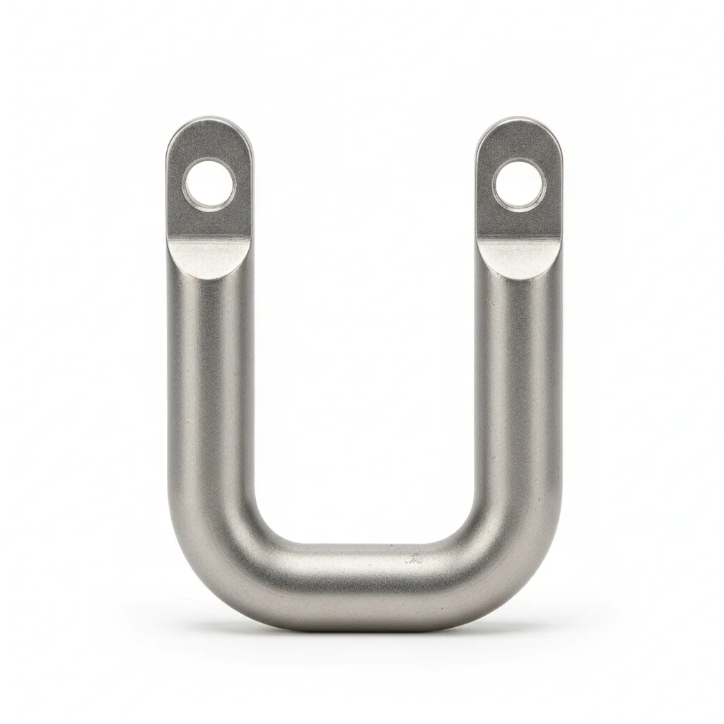
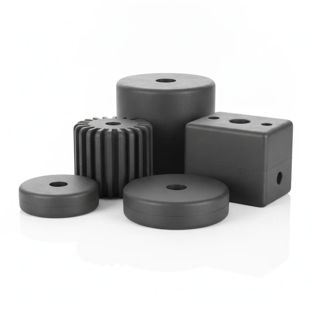
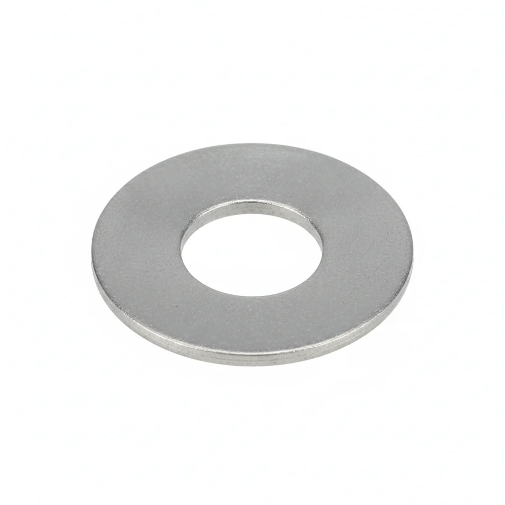
| Cable Clip | Self-tapping Screw | Rubber Bushing | Flat Washer | Flat Washer | |
|---|---|---|---|---|---|
| SPEC | Fits 4-10mm² | M4×12mm | 0.5mm thick | M10-M12 | M10-M12 |
| MATERIAL | 304 Stainless Steel | 304 Stainless Steel | EPDM | 304 Stainless | 304 Stainless |
| GRADE | A2-70 | A2-70 | — | A2 | A2 |
| FINISH | HDG >=55um per ISO 1461 | HDG >=55um per ISO 1461 | HDG >=55um per ISO 1461 | Passivated | Passivated |
| CORROSION | C3 (ISO 12944-2) | C3 (ISO 12944-2) | C3 (ISO 12944-2) | C3 (ISO 12944-2) | C3 (ISO 12944-2) |
| TEMP | -20°C to +80°C | -20°C to +80°C | -20°C to +80°C | -20°C to +80°C | -20°C to +80°C |
| WEIGHT | ~0.5 kg/piece | ~0.5 kg/piece | ~0.5 kg/piece | ~0.005kg | ~0.005kg |
| MOQ | 100 pcs | 100 pcs | 100 pcs | 500 pcs | 500 pcs |
| PACK | VCI paper + carton | VCI paper + carton | VCI paper + carton | Plastic bag | Plastic bag |
| STD | ISO 898-1, GB/T 3098.1 | ISO 898-1, GB/T 3098.1 | ISO 898-1, GB/T 3098.1 | ISO 7089 | ISO 7089 |
| USE | Coastal/high-humidity outdoor cable fixing | Cable clip fixing | Anti-wear protection for cables | Load distribution | Load distribution |
PROCEDURE
- Clean the light pole mounting surface and cable jacket; remove dirt and moisture.
- Position the 304 stainless steel cable clip around the cable, ensuring the EPDM rubber bushing sits between clip and cable.
- Secure the clip with M4×12mm self-tapping screws (A2-70) into the pole; tighten evenly to avoid deforming the clip.
- Space clips at 400-600mm intervals along the cable run, per GB 50303 for vertical runs, with a recommended 500mm spacing.
- Verify each clip holds the cable firmly without crushing the insulation; check that the cable can move slightly under hand force.
COMMON ERRORS
| ✕ WRONG | CONSEQUENCE | ✓ CORRECT |
|---|---|---|
| Using ordinary galvanized iron clamps (20-30μm coating) in acid rain (pH 4-5) | Galvanized layer depletes in 1-2 years; carbon steel corrodes at 0.05-0.1mm/year, reducing thickness from 1.0mm to <0.7mm in 3 years and cutting clamping force by >50%. | Select 304 stainless steel (A2-70) clips or hot-dip galvanized with ≥65μm coating; add insulating gaskets to prevent galvanic corrosion. |
| Installing clips with spacing greater than 1m on vertical cable runs | Cable sags ~15mm over 1.5m span; sagging section rubs pole inner wall, wearing PVC insulation at 0.1mm/year, exposing copper core after 5-7 years and causing short circuits. | Keep spacing 400-600mm (recommend 500mm) per GB 50303; use rubber-lined clips to reduce insulation wear. |
MAINTENANCE
Seasonally inspect clips for loosening or corrosion. Check that the 304 stainless steel surface remains free of rust; if any pitting appears, replace the clip. Verify clamping force by tugging the cable – it should not slip. Re-tighten self-tapping screws if loose. Replace any clip with cracked or deformed EPDM bushing.
Plan C · High-end
C5-M (ISO 12944-2) for marine environments; 316L stainless steel (A4-80) provides superior resistance to chloride-induced corrosion.
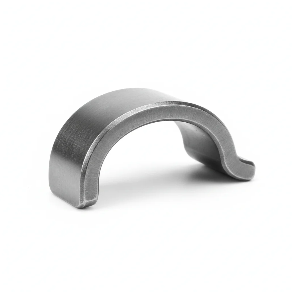
| Cable Clip | Self-tapping Screw | Silicone Rubber Bushing | Flat Washer | Flat Washer | |
|---|---|---|---|---|---|
| SPEC | Fits 4-10mm² | M4×12mm | 0.5mm thick | M10-M12 | M10-M12 |
| MATERIAL | 316L Stainless Steel | 316L | Silicone Rubber VMQ | 304 Stainless | 304 Stainless |
| GRADE | A4-80 | A4-80 | Temp. range -60~200°C | A2 | A2 |
| FINISH | HDG >=55um per ISO 1461 | HDG >=55um per ISO 1461 | HDG >=55um per ISO 1461 | Passivated | Passivated |
| CORROSION | C3 (ISO 12944-2) | C3 (ISO 12944-2) | C3 (ISO 12944-2) | C3 (ISO 12944-2) | C3 (ISO 12944-2) |
| TEMP | -20°C to +80°C | -20°C to +80°C | -20°C to +80°C | -20°C to +80°C | -20°C to +80°C |
| WEIGHT | ~0.5 kg/piece | ~0.5 kg/piece | ~0.5 kg/piece | ~0.005kg | ~0.005kg |
| MOQ | 100 pcs | 100 pcs | 100 pcs | 500 pcs | 500 pcs |
| PACK | VCI paper + carton | VCI paper + carton | VCI paper + carton | Plastic bag | Plastic bag |
| STD | ISO 898-1, GB/T 3098.1 | ISO 898-1, GB/T 3098.1 | ISO 898-1, GB/T 3098.1 | ISO 7089 | ISO 7089 |
| USE | Marine/extreme corrosion environment cable fixing | Extreme environment fixing | Extreme temperature environment protection | Load distribution | Load distribution |
PROCEDURE
- Clean the mounting surface with a marine-grade solvent to remove salts and contaminants.
- Position the 316L stainless steel cable clip with silicone rubber bushing (VMQ, -60~200°C) to protect the cable in extreme temperatures.
- Secure with 316L self-tapping screws (A4-80) into the pole; use appropriate torque to avoid stripping threads in the thin pole wall.
- Maintain 400-600mm spacing between clips (recommend 500mm) to prevent sagging and wear, even under high wind vibration.
- For vertical runs, install an anti-pull-out pressure plate at the cable outlet to prevent cable pull-out during gusts.
COMMON ERRORS
| ✕ WRONG | CONSEQUENCE | ✓ CORRECT |
|---|---|---|
| Using 304 stainless steel (A2-70) in a marine environment with salt spray | 304 can suffer pitting and crevice corrosion in chloride-rich coastal air, reducing clamping force and leading to cable detachment over time. | Use 316L stainless steel (A4-80) which has higher molybdenum content for superior resistance to chloride attack. |
| Overtightening the clip on the cable, crushing the insulation | Damaged insulation accelerates aging and increases leakage risk, especially in wet marine conditions. | Tighten until the clip holds the cable without visible deformation; use the silicone bushing to distribute pressure evenly. |
MAINTENANCE
Inspect clips twice a year (before and after storm season) for any signs of corrosion, especially around screw heads and edges. Verify that the silicone bushing remains flexible and intact. Check clamping force by attempting to slide the cable – it must not move. Replace any clip showing pitting or loss of material, and re-tighten screws if vibration has loosened them.
Weathering and UV Resistance
Outdoor clamps live under direct sunlight, rain and temperature swings. Coating and plastic parts are assessed by xenon-arc accelerated weathering testing per GB/T 18226, requiring no chalking, blistering or peeling of the coating over the test period. For metal clamps, the MTC material certificate and spectrographic analysis confirm grade and composition for each batch, and neutral salt spray (NSS) test reports are available on request. For UV-heavy sites, prefer UV-stabilized nylon or stainless steel over plain PVC.
Custom selection is supported by drawing, voltage class and outdoor environment requirements (UV, salt spray, temperature); submit via the inquiry form for a quotation tailored to your site conditions.
REFERENCED STANDARDS
Technical Basis and Reference Standards
Cable management systems - Requirements for cable cleats and cable supports
Safety Requirements for FloodlightsMechanical properties of fasteners - Bolts, screws and studs
Cable LayingCorrosion of metals and alloys - Classification, determination and assessment of atmospheric corrosivity
Design Standard for Power Engineering CablesDegrees of protection provided by enclosures (IP Code)
Cable ClampsStandard Specification for Chromium and Chromium-Nickel Stainless Steel Plate, Sheet, and Strip for Pressure Vessels
SUPPLIER CAPABILITY
Quality, Delivery & Customization
Quality Control
- ✓MTC material certificates with every batch
- ✓Key parts sampled for hardness/salt spray/torque coefficient
- ✓100% inspection or AQL sampling before shipment
Delivery
- ✓Standard parts made to order: 7-15 days
- ✓Custom parts: 25-45 days
- ✓FOB/CIF/DDP supported
Customization
- ✓Drawing review and material matching
- ✓Non-standard sizes/heads/threads
- ✓Small-batch prototyping supported
Certification
- ✓Material certificates (MTC)
- ✓Spectrographic analysis reports
- ✓Salt spray test reports (on request)
MOQ: No MOQ for standard parts; custom parts assessed by process complexity
FAQ
Frequently Asked Questions
RELATED READING
Keep Reading & Next Step
BEYOND TECHNICAL SPECS
Finding the right factory, controlling quality, delivering on time — that's the real challenge. We cover fasteners, rubber, plastics, industrial textiles. One team, end to end.
SEE CAPABILITIES →