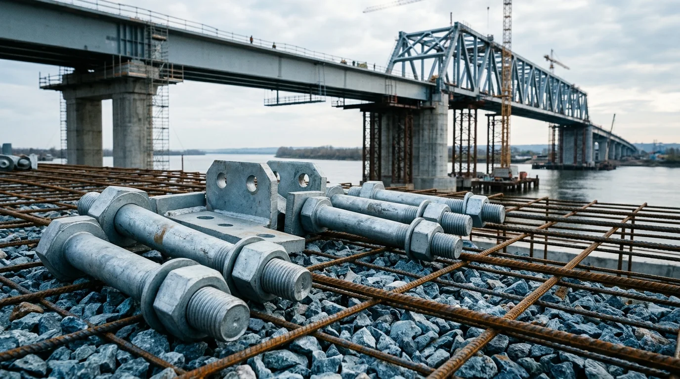
Shade Net Fixing Hardware: Compare Wire Rope Clips, Plastic Channels, and Rack and Pinion
Select the right fasteners and connectors for your greenhouse shade system. Compare Plan A (wire rope clips and turnbuckle bolts) for manual external shading, Plan B (plastic channel and spring clips) for internal film protection, and Plan C (rack and pinion) for electric smart greenhouses. Each plan includes product specs, lifespan, and maintenance requirements
RISK AUDIT // ENGINEERING DIAGNOSIS
Procurement Pitfall Guide
"Wire rope fatigue, plastic channel warping, and gear wear: the three failure modes that silently shut down your shade system."
QC-AUDIT // REV.5
SCALE 1:1 · 03 ITEMS
RISK-01
Shade Net Wire Rope Fatigue Breakage at Drive End Pulley
Corrective Measures
RISK-02
Plastic Channel High-Temperature Deformation and Stress Cracking
Corrective Measures
RISK-03
Rack and Pinion Wear and Jamming in Sandy Environments
Corrective Measures
FIELD-SPECIFIC INSIGHT
Key Differences in Shade Net Fixing Hardware
Each fixing method has distinct failure modes: wire rope fatigue at pulleys, plastic channel deformation under high temperature, and rack and pinion wear in dusty environments. The choice depends on shading type, environment, and automation level
WHAT TO CHECK
- 1Wire rope clips (Φ4, HDG) suit manual external shading; inspect for broken wires after repeated bending cycles (2-3 years)
- 2Plastic channels (PE, UV stabilized) risk warping at high surface temperatures; replace if deformed after 2 seasons
- 3Rack and pinion (aluminum alloy + PA66 gear) may jam in sandy conditions; check clearance increase after 500 cycles
- 4Turnbuckle bolts (M8, travel 100mm) require re-torquing if tension loss exceeds 15%
| Check | Why it matters | What to specify |
|---|---|---|
| Wire rope clip torque | Under-torqued clips cause rope slip; over-torqued clips damage strands | Torque per manufacturer spec; verify with torque wrench |
| Plastic channel UV resistance | Non-UV stabilized channels crack within 1 season | UV stabilized PE; request UV test report per ISO 4892 |
| Rack and pinion backlash | Excessive backlash reduces positioning accuracy and causes jamming | Initial backlash per spec; re-adjust if increased |
| Hot-dip galvanizing thickness | Insufficient coating leads to early corrosion in C3-C5 environments | Verify with magnetic thickness gauge |
Lifespan estimates assume regular maintenance per plan. Actual service life depends on local climate and operating conditions
Evidence level: source-page-only
INDUSTRY TECH REFERENCE
Before Mounting Shading on a Multi-Span: Size the Joint Bolts by Snow Zone
External shading mounts on the multi-span greenhouse frame. Snow loads the roof and drifts into piles, and the load comes back through the gutters to the joint bolts — so tier the structural mounting points of your shade system by the site's snow zone before settling on sizes and counts.
| Snow zone / city | Reference snow pressure | Joint bolt configuration | Shear capacity basis |
|---|---|---|---|
| Changchun | 0.35 kN/m² (GB 50009-2012, Annex E.5) | M10–M12 grade 8.8, ≥4 bolts per joint | ≈29 kN per bolt (0.6×830 MPa×58 mm²), ≈110 kN for 4 bolts |
| Harbin | 0.45 kN/m² | M10–M12 grade 8.8, ≥4 bolts per joint | ≈29 kN per bolt, ≈110 kN for 4 bolts |
| Shenyang | 0.50 kN/m² | M10–M12 grade 8.8, ≥4 bolts per joint | ≈29 kN per bolt, ≈110 kN for 4 bolts |
| Higher snow zone (>0.5 kN/m²) | — | M12, 6 bolts per joint | six bolts raise the load capacity |
Snow-pressure zones and city values follow GB 50009-2012 (Annex E.5); ≈29 kN per bolt is a 0.6×σb×As calculated value and ≈110 kN for four (unreduced); the M12×6 high-snow configuration is a sizing rule.
INDUSTRY TECH REFERENCE
Standards to Match When Specifying Shade-Net Fixings
Match these standards for duty and acceptance when you order shade-net fixings and their structural mounting parts.
The listed standards (GB 50009-2012, GB/T 2518, GB/T 1222-2025, ISO 9223) are public navigation references — no standard tables reproduced; Z275 ≈ 20 μm per side is the GB/T 2518 grade conversion.
PLAN COMPARISON
Three-Plan Core Parameter Comparison
Compare row by row. Click column headers to jump to plan details.
| A · Plan A · Wire Rope Clips and Turnbuckle Bolts | B · Plan B · Plastic Channel and Spring Clips | C · Plan C · Rack and Pinion Drive Connectors | |
|---|---|---|---|
| 1. Φ4 WIRE ROPE CLIP | |||
| SPEC | Hot-dip Galvanized, GB/T 5976 | Width 30mm, UV Stabilized | Module 1.5, Length 2m |
| MATERIAL | Q235B | PE | Aluminum Alloy |
| FINISH | HDG >=55um per ISO 1461 | HDG >=55um per ISO 1461 | HDG >=55um per ISO 1461 |
| 2. M8 TURNBUCKLE BOLT | |||
| SPEC | Travel 100mm, Galvanized | Galvanized Steel Wire, Φ2 | PA66+GF30, Module 1.5 |
| MATERIAL | — | — | PA66 |
| FINISH | HDG >=55um per ISO 1461 | HDG >=55um per ISO 1461 | HDG >=55um per ISO 1461 |
| 3. WIRE ROPE | |||
| SPEC | Φ4mm, 7×19 Construction | Self-tapping Screw, ST4.2×16 | Flexible Jaw Type, Φ14 |
| MATERIAL | Q235B | — | — |
| FINISH | HDG >=55um per ISO 1461 | HDG >=55um per ISO 1461 | HDG >=55um per ISO 1461 |
Plan A · Wire Rope Clips and Turnbuckle Bolts
C3 (ISO 12944-2) for hot-dip galvanized components in external shading environment
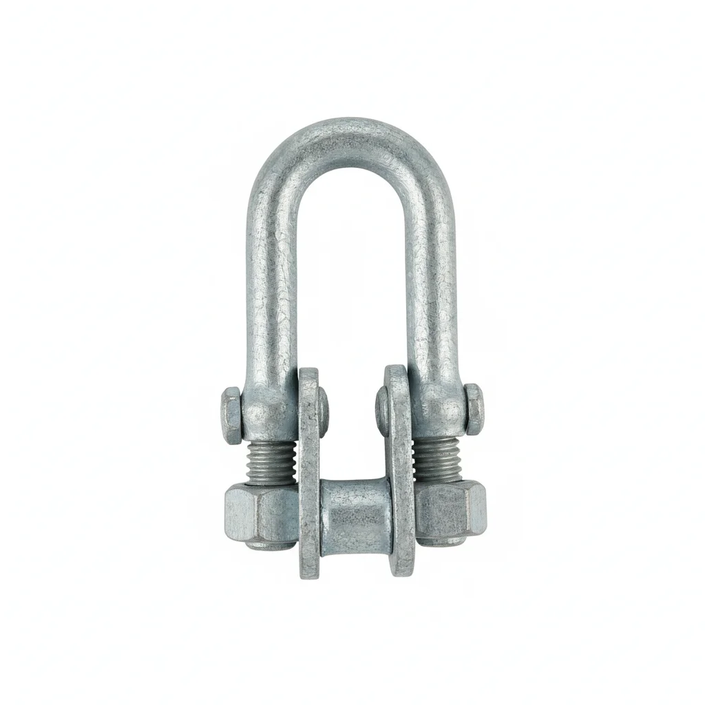
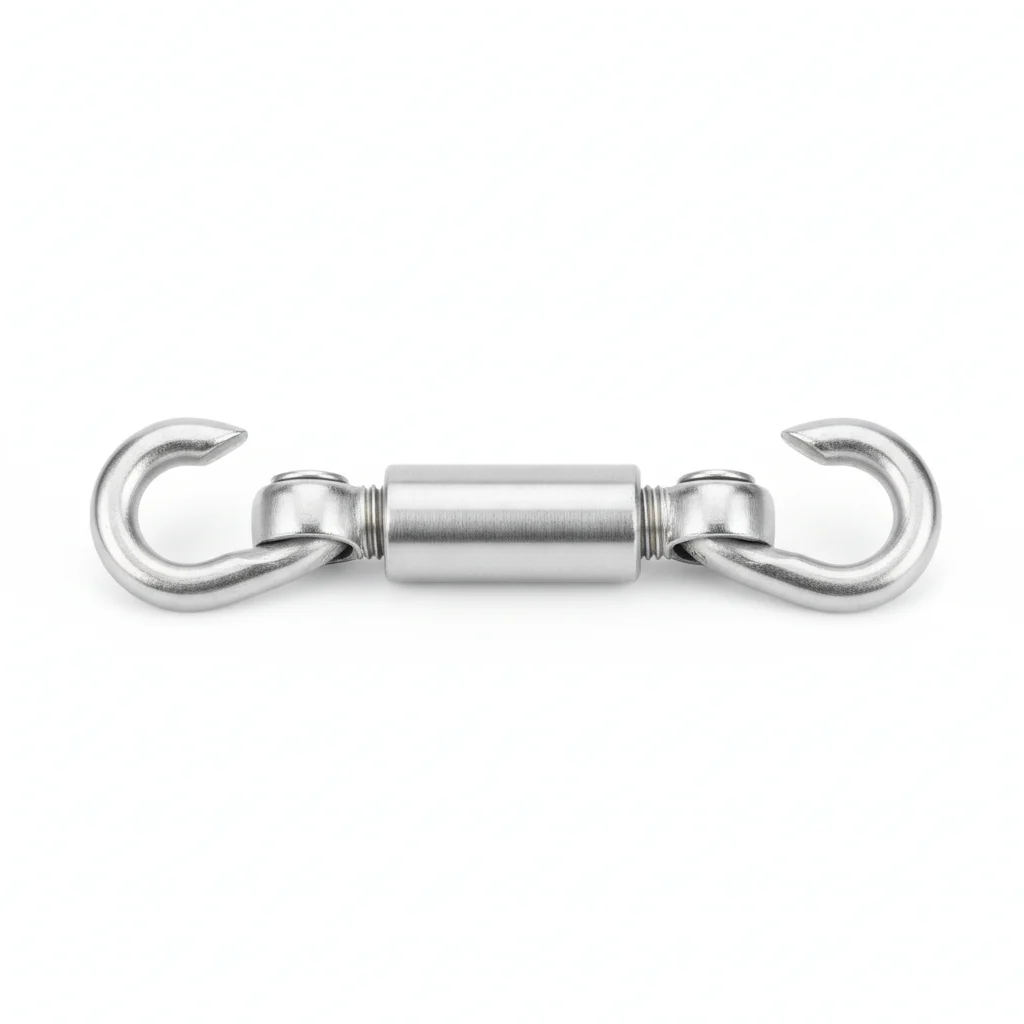
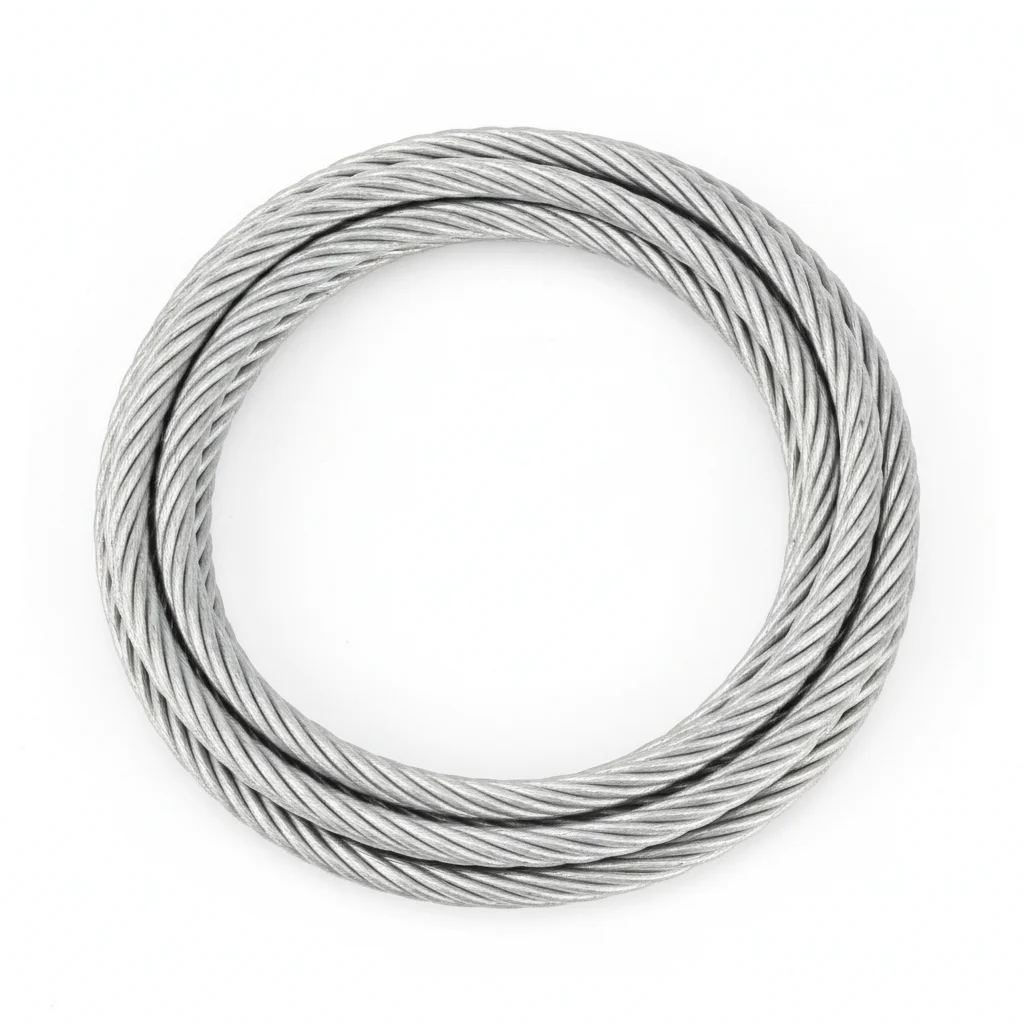
| Φ4 Wire Rope Clip | M8 Turnbuckle Bolt | Wire Rope | |
|---|---|---|---|
| SPEC | Hot-dip Galvanized, GB/T 5976 | Travel 100mm, Galvanized | Φ4mm, 7×19 Construction |
| MATERIAL | Q235B | — | Q235B |
| GRADE | — | — | — |
| FINISH | HDG >=55um per ISO 1461 | HDG >=55um per ISO 1461 | HDG >=55um per ISO 1461 |
| CORROSION | C3 (ISO 12944-2) | C3 (ISO 12944-2) | C3 (ISO 12944-2) |
| TEMP | -20°C to +80°C | -20°C to +80°C | -20°C to +80°C |
| WEIGHT | ~0.5 kg/piece | ~0.5 kg/piece | ~0.5 kg/piece |
| MOQ | 100 pcs | 100 pcs | 100 pcs |
| PACK | VCI paper + carton | VCI paper + carton | VCI paper + carton |
| STD | ISO 898-1, GB/T 3098.1 | ISO 898-1, GB/T 3098.1 | ISO 898-1, GB/T 3098.1 |
| USE | GB/T 5976 | Galvanized | 7×19 Construction |
PROCEDURE
- Lay out the Φ4 wire rope along the shade net support structure, ensuring the 7×19 construction runs freely without kinks.
- Secure the wire rope with Φ4 wire rope clips at each anchorage point, positioning the U-bolt on the dead end and the saddle on the live end per GB/T 5976.
- Thread the M8 turnbuckle bolt into the rope loop; adjust the travel to achieve the desired shade net tension, leaving adjustment margin for seasonal changes.
- Tighten the clip nuts evenly with a torque wrench to the manufacturer's specified value; avoid over-torquing which can crush the wire rope strands.
- After initial tensioning, re-check and re-tighten the clips after 24 hours and again after the first week of operation to account for rope seating.
COMMON ERRORS
| ✕ WRONG | CONSEQUENCE | ✓ CORRECT |
|---|---|---|
| Placing the wire rope clip U-bolt on the live (load-bearing) end of the rope | The rope can slip through the clip under load, causing the shade net to sag or detach, leading to crop damage. | Always mount the U-bolt on the dead (non-load) end and the saddle on the live end, per standard wire rope clip practice. |
| Overtightening the M8 turnbuckle bolt beyond its designed travel limit | Excessive tension can overstress the wire rope and clips, leading to premature fatigue failure or deformation of the support structure. | Adjust the turnbuckle to achieve the recommended tension, using the travel range (100mm) as a guide and leaving allowance for thermal expansion and wind loads. |
MAINTENANCE
Seasonally inspect the wire rope at the drive end pulley and all clip locations for broken wires; replace the entire rope if broken wires exceed 5% of the total (13 wires for 7×19). Re-tension the turnbuckle bolts if sag is observed, and verify clip torque remains within specification. At each overhaul window (typically every 2-3 years depending on usage), replace clips showing corrosion or deformation.
Plan B · Plastic Channel and Spring Clips
C3 (ISO 12944-2) indoor microclimate, high humidity, UV exposure
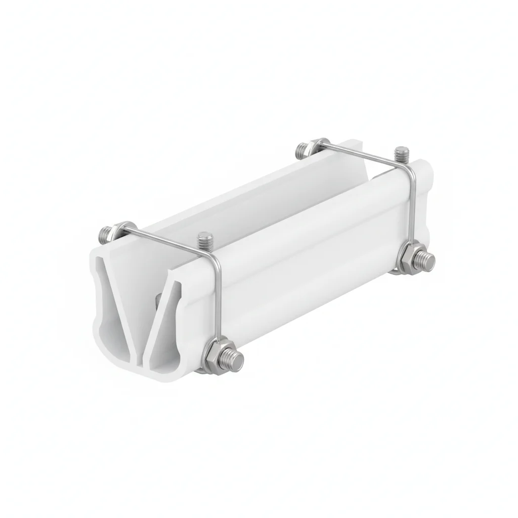
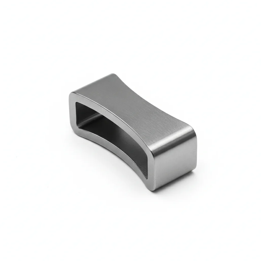
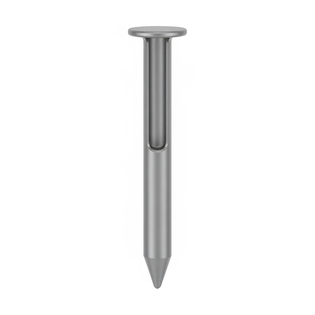
| Channel | Spring Clip | Channel Fixing Nail | |
|---|---|---|---|
| SPEC | Width 30mm, UV Stabilized | Galvanized Steel Wire, Φ2 | Self-tapping Screw, ST4.2×16 |
| MATERIAL | PE | — | — |
| GRADE | — | — | — |
| FINISH | HDG >=55um per ISO 1461 | HDG >=55um per ISO 1461 | HDG >=55um per ISO 1461 |
| CORROSION | C3 (ISO 12944-2) | C3 (ISO 12944-2) | C3 (ISO 12944-2) |
| TEMP | -20°C to +80°C | -20°C to +80°C | -20°C to +80°C |
| WEIGHT | ~0.5 kg/piece | ~0.5 kg/piece | ~0.5 kg/piece |
| MOQ | 100 pcs | 100 pcs | 100 pcs |
| PACK | VCI paper + carton | VCI paper + carton | VCI paper + carton |
| STD | ISO 898-1, GB/T 3098.1 | ISO 898-1, GB/T 3098.1 | ISO 898-1, GB/T 3098.1 |
| USE | UV Stabilized | Φ2 | ST4.2×16 |
PROCEDURE
- Lay the UV-stabilized PE channel (30mm width) along the greenhouse purlin, aligning the fixing holes with the support structure.
- Drive the ST4.2×16 self-tapping screws through the channel base into the purlin, spacing them evenly to prevent sagging.
- Insert the shade net edge into the channel groove, ensuring it is fully seated without wrinkles.
- Press the Φ2 galvanized spring clips into the channel at regular intervals, starting from the center and working outward to distribute tension evenly.
- Verify that each spring clip fully engages the channel lip and that the net is held firmly without gaps.
COMMON ERRORS
| ✕ WRONG | CONSEQUENCE | ✓ CORRECT |
|---|---|---|
| Using ordinary (non-UV-stabilized) PE channel | Channel becomes brittle and cracks within one season under greenhouse UV exposure, causing the shade net to detach. | Specify UV-stabilized PE channel (as per product spec) to ensure 8-12 year lifespan. |
| Overdriving the self-tapping screws, causing channel deformation | Deformed channel prevents spring clips from seating properly, leading to net slippage. | Drive screws until snug, not over-tightened, to maintain channel profile. |
| Installing spring clips at too wide intervals | Net may billow or pull out between clips under wind load. | Space clips at recommended intervals (e.g., every 30-50 cm) to ensure secure hold. |
MAINTENANCE
Seasonally inspect channel for UV embrittlement or deformation; replace any channel showing cracks or loss of clamping force. Check spring clip tension and re-seat or replace clips that have lost spring force. Clean channel grooves of debris that could impair clip engagement.
Plan C · Rack and Pinion Drive Connectors
C3 (ISO 12944-2) with dust and cyclic loading in smart greenhouse environment
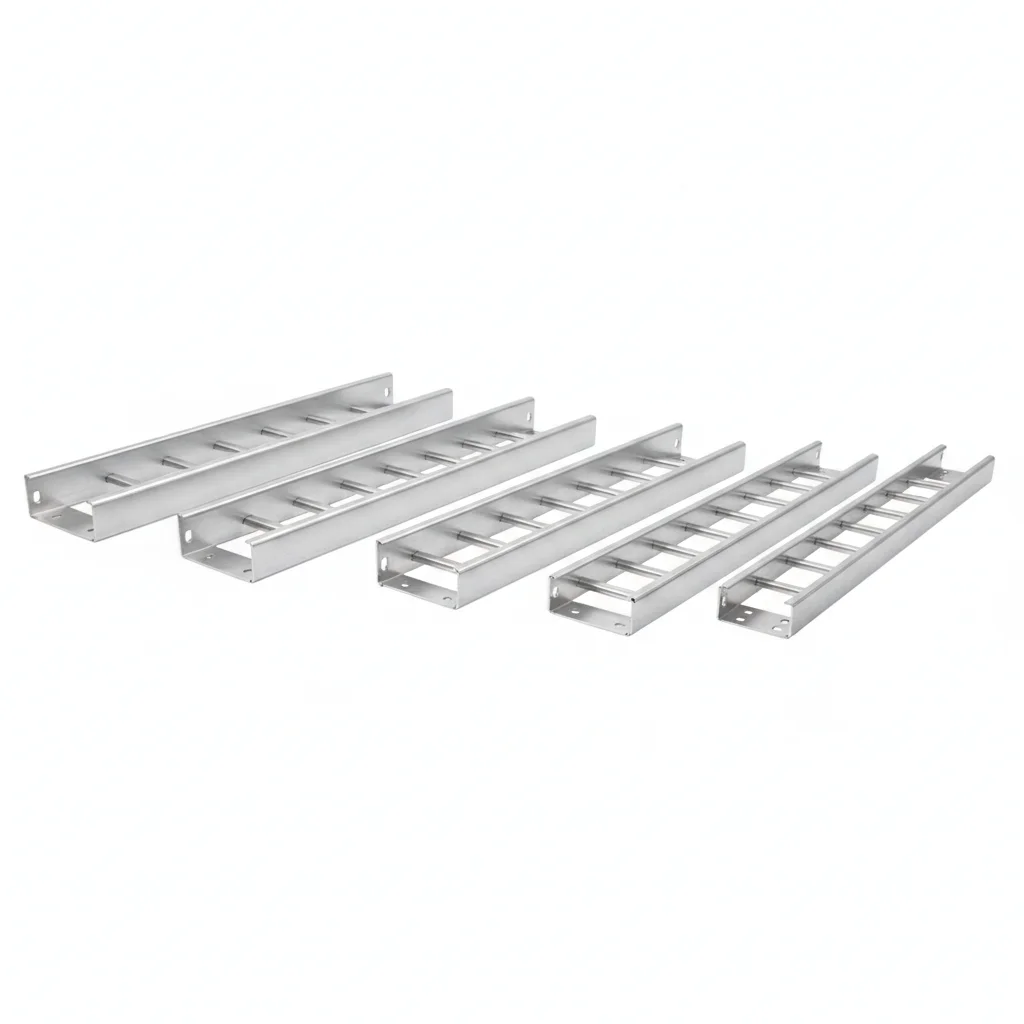
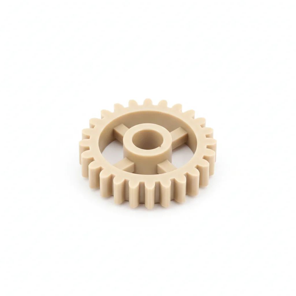
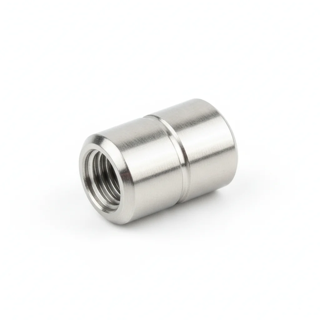
| Aluminum Alloy Rack | Nylon Gear | Coupling | |
|---|---|---|---|
| SPEC | Module 1.5, Length 2m | PA66+GF30, Module 1.5 | Flexible Jaw Type, Φ14 |
| MATERIAL | Aluminum Alloy | PA66 | — |
| GRADE | — | — | — |
| FINISH | HDG >=55um per ISO 1461 | HDG >=55um per ISO 1461 | HDG >=55um per ISO 1461 |
| CORROSION | C3 (ISO 12944-2) | C3 (ISO 12944-2) | C3 (ISO 12944-2) |
| TEMP | -20°C to +80°C | -20°C to +80°C | -20°C to +80°C |
| WEIGHT | ~0.5 kg/piece | ~0.5 kg/piece | ~0.5 kg/piece |
| MOQ | 100 pcs | 100 pcs | 100 pcs |
| PACK | VCI paper + carton | VCI paper + carton | VCI paper + carton |
| STD | ISO 898-1, GB/T 3098.1 | ISO 898-1, GB/T 3098.1 | ISO 898-1, GB/T 3098.1 |
| USE | Length 2m | Module 1.5 | Φ14 |
PROCEDURE
- Mount the aluminum alloy rack (module 1.5, 2m length) along the drive shaft, aligning the rack teeth with the PA66+GF30 gear.
- Secure the rack to the greenhouse frame using stainless steel bolts, ensuring the rack is straight and level.
- Attach the flexible jaw coupling (Φ14) to the gearmotor shaft and the drive shaft, verifying alignment to prevent vibration.
- Engage the nylon gear with the rack, adjusting the mesh depth to the manufacturer's specification for smooth operation.
- Connect the drive system to the control unit and perform a manual jog test to confirm full travel without binding.
- Lock all fasteners with thread-locking adhesive and apply anti-seize compound to the coupling bolts.
COMMON ERRORS
| ✕ WRONG | CONSEQUENCE | ✓ CORRECT |
|---|---|---|
| Misaligning rack and pinion teeth during installation | Excessive backlash and uneven wear, leading to jamming or premature gear failure. | Use alignment tool to ensure rack and pinion are parallel and mesh depth is correct. |
| Over-tightening coupling bolts, causing shaft distortion | Vibration and premature bearing failure in the gearmotor. | Tighten coupling bolts to the specified torque (per coupling manufacturer) to allow slight flexibility. |
| Neglecting to apply anti-seize to stainless bolts in aluminum rack | Galvanic corrosion between aluminum and stainless steel, seizing threads over time. | Apply anti-seize compound to all stainless-aluminum interfaces before assembly. |
MAINTENANCE
At each overhaul window, inspect rack teeth for wear and gear for backlash; if backlash exceeds 0.3mm, adjust or replace. Lubricate rack and pinion with food-grade grease compatible with PA66. Check coupling for wear and re-torque bolts after first season. Clean dust from drive components to prevent abrasive wear.
SELECTION GUIDE
How to Choose the Fixing Method Based on Your Shade System?
| Operating condition | Recommended option | Key basis |
|---|---|---|
| Limited budget, manual shading operation — external shading system / single greenhouse | Plan A: wire rope clips (Φ4, hot-dip galvanized, GB/T 5976) + M8 turnbuckle bolts (travel 100mm, galvanized) + wire rope (Φ4mm, 7×19 construction); reserve tension adjustment margin — external shading must withstand level 8 winds (17.2-20.7 m/s) | GB/T 5976; GB/T 13912; ISO 12944-2 (C3) |
| Multi-span greenhouse, internal shading film protection (indoor microclimate, high humidity, UV exposure) | Plan B: plastic channel (width 30mm, UV-stabilized PE) + spring clips (galvanized steel wire, Φ2) + channel fixing nails (self-tapping screws ST4.2×16) | ISO 12944-2 (C3); ISO 4892 |
| Smart control, automatic opening/closing — smart greenhouse (dust + cyclic loading) | Plan C: rack and pinion drive — aluminum alloy rack (module 1.5, length 2m) + nylon gear (PA66+GF30, module 1.5) + flexible jaw coupling (Φ14); requires geared motor | ISO 12944-2 (C3); GB/T 1040 |
| Drive end pulley of external shade net under repeated daily opening/closing bending | Specify pulley diameter ≥20× wire rope diameter (e.g., Φ3mm wire rope with Φ60mm or larger pulley); inspect the drive end each season and replace the rope when broken wires exceed 5% — fatigue starts after 10^4 bending cycles (about 2-3 years) | GB 50017; GB/T 13912 |
| High-temperature summer environments (surface temperature up to 85°C) for internal shading | Use reinforced nylon channel (PA66+30% glass fiber, -40°C to 120°C, metal inner liner skeleton, thermal expansion controlled within 0.5%) instead of ordinary PP/PE (lifespan under 2 seasons); UV-stabilized PE channels last 8-12 years under normal conditions | ISO 527; ASTM D638; ISO 4892 |
REFERENCED STANDARDS
Technical Basis and Reference Standards
"Greenhouse Shading System"
Metallic Coatings - Hot Dip Galvanized Coatings"Agricultural Plastic Film"
Plastics - Tensile Test"Plastic Channel"
Plastics - Tensile PropertiesPlastics - Methods of exposure to laboratory light sources
Plastics - Tensile Test"Technical Conditions for Solar Greenhouse"
SUPPLIER CAPABILITY
Quality, Delivery & Customization
Quality Control
- ✓MTC material certificates with every batch
- ✓Key parts sampled for hardness/salt spray/torque coefficient
- ✓100% inspection or AQL sampling before shipment
Delivery
- ✓Standard parts made to order: 7-15 days
- ✓Custom parts: 25-45 days
- ✓FOB/CIF/DDP supported
Customization
- ✓Drawing review and material matching
- ✓Non-standard sizes/heads/threads
- ✓Small-batch prototyping supported
Certification
- ✓Material certificates (MTC)
- ✓Spectrographic analysis reports
- ✓Salt spray test reports (on request)
MOQ: No MOQ for standard parts; custom parts assessed by process complexity
FAQ
Frequently Asked Questions
RELATED READING
Keep Reading & Next Step
NEXT: SELECTION & RFQ
Greenhouse Film Fixing ClampsFollow this page's selection path to the same-scenario RFQ page.
RELATED TOPIC
Greenhouse Film Fixing ClampsRELATED TOPIC
Greenhouse Frame ConnectorsBEYOND TECHNICAL SPECS
Finding the right factory, controlling quality, delivering on time — that's the real challenge. We cover fasteners, rubber, plastics, industrial textiles. One team, end to end.
SEE CAPABILITIES →