Fan and Duct Fasteners: Preventing Loosening and Corrosion Failure
A 15kW centrifugal fan at full load can generate excitation forces of several hundred kilograms—if the fan base bolts loosen → the fan 'jumps' on the foundation → coupling misalignment → bearing life drops from 50,000h to 5,000h. Duct flange bolts under vibration experience fretting wear → preload loss → flange leaks → system air volume loss of 10-20%. This page compares fastener solutions for general ventilation and high-temperature exhaust
RISK AUDIT // ENGINEERING DIAGNOSIS
Procurement Pitfall Guide
"On the production line, a loose base bolt or a leaking flange can shut down the whole ventilation system."
QC-AUDIT // REV.5
SCALE 1:1 · 03 ITEMS
RISK-01
Fan Base Bolts Loosening Under Resonance
Corrective Measures
RISK-02
Duct Flange Bolts Loosening Under Pulsating Airflow Vibration
Corrective Measures
RISK-03
Bolt Corrosion Failure in Corrosive Environments
Corrective Measures
FIELD-SPECIFIC INSIGHT
Critical Checks for Fan and Duct Fastener Procurement
The most overlooked engineering difference is the interaction between fan vibration frequency and fastener preload. Standard bolts without vibration-resistant features will loosen over time, causing cascading failures
WHAT TO CHECK
- 1Fan base bolts: Use grade 10.9 bolts with double nuts and monthly torque verification to prevent loosening under resonance
- 2Duct flange bolts: Specify grade 8
- 3For high-temperature exhaust (>200°C): Use 304 stainless steel bolts with ceramic washers to prevent galling and maintain preload
- 4Corrosive environments (C4/C5): Require stainless steel (A2-70 or A4-80) and inspect for pitting depth >0.3mm annually
| Check | Why it matters | What to specify |
|---|---|---|
| Bolt grade and coating | Incorrect grade leads to preload loss under vibration; wrong coating causes rapid corrosion | Grade 10.9 for fan base, grade 8.8 for duct flanges |
| Vibration isolator natural frequency | If isolator frequency >0.7× fan speed, resonance amplifies bolt loads | Spring isolator natural frequency <0.7× fan operating speed |
| Torque verification interval | Without periodic re-torque, preload decays below 80% of specified torque, risking loosening | Inspect every 250 operating hours or 6 months; re-torque if below 80% |
| Corrosion allowance for pitting | Pitting depth >0.3mm reduces bolt cross-section and accelerates stress corrosion cracking | Replace bolts with pitting depth >0.3mm or corrosion affecting >5% surface area |
Maximum allowable tension loss is 15% per maintenance schedule. All inspections must be documented in CMMS
Evidence level: source-page-only
INDUSTRY TECH REFERENCE
From Impeller Dust to a Flying Blade: The Fan Vibration Failure Chain
Fan fastener failures rarely happen in isolation — dust build-up, unbalance, base loosening, and blade fatigue form one chain with numbers at every link. Walk the chain to see where each alarm line sits and where to intervene.
- 1Dust build-up or erosion removes impeller mass → the centre of gravity shifts → unbalance force F=m·e·ω² grows with the square of speed — unbalance is the source of roughly 40% of rotating-machinery vibration
- 2Vibration climbs past the Zone B ceiling of 4.5 mm/s (ISO 10816-3 criterion, long-term operation allowed) and heads toward the first alarm line of 7.1 mm/s (start of Zone C)
- 3Under whole-machine vibration the base/floor fasteners take alternating load — an OEM account ranks 'base fasteners not secure enough to the floor' third among seven vibration causes — preload decays, they loosen, support stiffness drops, and vibration amplifies further (positive feedback)
- 4The amplified vibration raises alternating stress on the impeller, and cracks initiate and grow at the blade root/welds — a demonstrated link: loose bearing → over-vibration → blade fatigue fracture (ID-fan failure analysis); a 300 MW FD-fan blade failed after vibration had reached 14 mm/s, nearly double the 7.1 mm/s alarm line
- 5At fracture the unbalance steps abruptly and can scrap the whole machine. Intervention points: act on vibration ≥7.1 mm/s; scheduled cleaning and field balancing; rebalance the impeller after welding or cleaning
The roughly 40% share of vibration sources from unbalance is an order-of-magnitude estimate; the 4.5/7.1 mm/s figures are ISO 10816-3 zone criteria and 14 mm/s is a measured pre-failure value from the blade-fracture case — directly checkable.
INDUSTRY TECH REFERENCE
Ventilation Fastener Locations: From Impeller Lock to High-Temp Flange
Fasteners on an industrial ventilation line split by location: the impeller lock is set at assembly for life, base bolts and couplings sit on the vibration patrol route, duct flanges are accepted to GB 50243, and high-temperature flanges follow an engineering-case hot retightening regime. The table lists the hardware, key parameters, and maintenance cadence for each point.
| Location | Fastener | Key parameters | Maintenance cadence |
|---|---|---|---|
| Fan·impeller-to-shaft lock | Tapered adapter sleeve + KM lock nut (DIN 981) + MB tab washer (DIN 5406) | Metric fine thread; washer single-use; SKF 22220 EK example: tighten nut to rotation angle α=150°; assemble by one of three methods — clearance reduction, nut angle, or axial push-up | Set once at assembly; replace the washer at every major overhaul |
| Fan·impeller balancing | (balance-weight screws, supporting hardware) | Balance grade G6.3 (AMCA BV-3) standard, G2.5 optional; rebalance after cleaning or weld repair | Vibration patrol: Zone B ≤4.5 mm/s, alarm at 7.1 mm/s |
| Fan·base/footing | Anchor bolts + grout | A known loosening hotspot (third of the seven OEM vibration causes); sight-line marks + vibration spectrum for detection | Fold into the vibration patrol route |
| Fan·coupling | Coupling bolts | Misalignment contributes ≥30% of vibration sources | Re-tighten after laser alignment |
| Duct·angle-flange joint | Bolts + nuts + gasket | M6 (small) / M8 (large); bolt pitch ≤150 mm for light/medium/low-pressure, ≤100 mm for high-pressure; rectangular flanges need corner holes | Leak inspection |
| Duct·standing-seam flange & flexible connector | Spring clips / U-bolts (GB); 3/8 in corner bolts + 6 in cleats (SMACNA TDC/TDF) | Spring-clip spacing ≤150 mm, ≤100 mm in clean rooms, fixed alternately in opposite directions; flexible connector 150–250 mm; expansion joint on straight runs >20 m | — |
| High-temp exhaust·flange | Heat-resistant steel bolts (carbon→stainless→heat-alloy transition temperature unregistered — a known gap) | 925°F (≈496°C) case: centre-mounted volute support, 4 in bearing insulation, ANSI 150 lb flanges against high-temperature warping | Hot retightening regime (analogous to pipe hot-tightening; no dedicated code in this domain) |
The ≥30% misalignment share of vibration sources is an order-of-magnitude estimate; the remaining figures are public-standard clauses (GB 50243-2016, AMCA BV-3) and official assembly parameters (DIN 981/DIN 5406, SKF 22220 EK) — directly checkable.
INDUSTRY TECH REFERENCE
Three Numbers for Fan Fastener Checks: Vibration Limit, Lock-Nut Angle, Balance Grade
A fan runs continuously — stopping it stops the dust collection system and the line's environmental compliance, so fastener checks ride along on the vibration patrol. One number for inspection and one for assembly catches most failures before they become faults.
- Two vibration numbers: Zone B ≤4.5 mm/s allows long-term operation; ≥7.1 mm/s is the first alarm and must be acted on (ISO 10816-3/ISO 20816-1) — impeller dust/erosion is the main vibration driver, so check impeller build-up and base sight-line marks on the same round
- One lock-nut angle: SKF 22220 EK officially recommends tightening to α=150°; the three mounting methods for tapered-bore bearings are clearance reduction, nut rotation angle, and axial push-up — a procedure job set by angle or advance, not by feel
- Put the balance grade in the spec sheet: BV-3 = ISO G6.3 standard, G2.5 optional for demanding users; rebalance the impeller after cleaning or weld repair
- Two coupling/base checks: misalignment contributes ≥30% of vibration sources (re-tighten after laser alignment); base/floor fasteners are the known loosening hotspot — detect by sight-line marks plus vibration spectrum
The ≥30% misalignment share of vibration sources is an order-of-magnitude estimate; the remaining figures are public-standard criteria (ISO 10816-3, AMCA BV-3) and official assembly/balance data (SKF, Greenheck technical bulletin).
INDUSTRY TECH REFERENCE
Which Standards Govern Ventilation Fastener Acceptance
Match the standards before quoting and accepting: duct flanges are verified to GB 50243 for pitch and bolt sizes, fan balance and vibration to the AMCA/ISO series, shaft locking to DIN 981/5406, and combustible-dust duty to NFPA and AMCA 99-0401 — each standard owns one stretch of the chain.
The standards listed in this slot are all public standards; only standard numbers, editions and scope are given for procurement navigation — specific acceptance values are per the current clauses of each standard. No order-of-magnitude estimates are used in this slot.
INDUSTRY TECH REFERENCE
Lock-Nuts on Adapter Sleeves: Locked by Tabs, Not by Torque
The impeller-to-shaft lock is a 'set at assembly for life' job on the fan side — and it is not the tightening torque that holds it. Understand form locking, and you know where a failure actually starts.
The impeller-to-shaft lock is a form-locked assembly of a tapered adapter sleeve + KM lock nut (DIN 981) + MB tab washer (DIN 5406): the washer's inner tab engages the shaft slot and the outer tab is bent into the nut slot, so with correct tabbing the nut physically cannot back out — 'the lock nut loosens by itself after many starts' is not the failure starting point. 'Just tighten it again' is the common field habit; real failures start in one of three places: 1) the adapter sleeve is not pushed up far enough (insufficient advance or lock angle) → fretting creep on the mating faces; 2) the tab washer is not tabbed or is reused beyond life; 3) fretting wear of the keyed connection. The consequence chain — impeller axial drift → unbalance → severe vibration → base loosening — is corroborated by OEM field experience. The assembly anchor: SKF 22220 EK officially recommends tightening the lock nut to α=150°, installed by one of three methods (clearance-reduction measurement, nut-angle measurement, or axial push-up measurement) — lock-nut tightening is a procedure job set by angle and advance, not by feel; the washer is single-use, replace it at every major overhaul.
No order-of-magnitude estimates are used in this slot.
PLAN COMPARISON
Three-Plan Core Parameter Comparison
Compare row by row. Click column headers to jump to plan details.
| A · A · General Ventilation | B · B · High Temperature / Industrial Exhaust | C · Plan C · Explosion-Proof / Clean Room | |
|---|---|---|---|
| 1. GRADE 10.9 FAN BASE BOLT | |||
| SPEC | M16-M24 | M16-M24 | M16-M24 |
| MATERIAL | 42CrMo | 304 | 316L |
| GRADE | Grade 10.9 Dacromet | A2-70 | A2-70 |
| FINISH | HDG >=55um per ISO 1461 | HDG >=55um per ISO 1461 | HDG >=55um per ISO 1461 |
| 2. GRADE 8.8 DUCT FLANGE BOLT | |||
| SPEC | M8-M10 | M8-M12 | M8-M12 |
| MATERIAL | Carbon Steel | 304 + Ceramic Fiber | 316L + Ceramic Fiber |
| GRADE | Grade 8.8 Hot-Dip Galvanized | — | — |
| FINISH | HDG >=55um per ISO 1461 | HDG >=55um per ISO 1461 | HDG >=55um per ISO 1461 |
SELECTION GUIDE
How to Choose Your Fan and Duct Fastener Solution
| Operating condition | Recommended option | Key basis |
|---|---|---|
| General ventilation (C3 Standard per ISO 12944-2; vibration duty per ISO 14694) | Plan A · General Ventilation: Grade 10.9 fan base bolt M16-M24 (42CrMo, Dacromet) + Grade 8.8 duct flange bolt M8-M10 (carbon steel, hot-dip galvanized) | ISO 14694 industrial fan vibration; SMACNA duct construction standards |
| High-temperature smoke exhaust >200°C (C4 Harsh per ISO 12944-2) | Plan B · High Temperature / Industrial Exhaust: 304 stainless steel fan bolt M16-M24 (A2-70) + 304 duct flange bolt M8-M12 with ceramic fiber washer | SMACNA duct construction standards; GB/T 1236 fan performance test |
| Explosion-proof areas / cleanrooms / high-temperature smoke exhaust (C5-M Extreme per ISO 12944-2) | Plan C · Explosion-Proof / Clean Room: full 304/316 stainless steel range (316L fan bolt M16-M24, A2-70; 316L duct flange bolt M8-M12 with ceramic fiber) + anti-static grounding + ATEX certification | GB/T 1236 fan performance test; SMACNA |
| Fan base under resonance: rotational speed passes through the natural frequency range at start-up, instantaneous amplitude reaches 3-5× normal, preload decays stepwise | Grade 10.9 bolts + double nuts + spring vibration isolators (isolator natural frequency <0.7× fan speed); vibration test after installation — fan bearing housing vibration velocity <4.5 mm/s (ISO 14694); retighten base bolt torque quarterly | ISO 14694 industrial fan vibration |
| Corrosive environments (chemical/marine: temperature 80~120°C, relative humidity 85%, chloride ion concentration 200 ppm, pitting up to 0.5 mm/year, designed service life cut from 10 years to 1.5 years) | Use 316L stainless steel or titanium alloy with anti-corrosion coating (e.g. zinc-chromium coating) + sealing gaskets + corrosion-resistant thread-locking adhesive to fill thread gaps; for C4/C5 specify stainless steel (A2-70 or A4-80) and inspect annually for pitting depth >0.3mm | ISO 12944-2 (C4/C5 environment classification); SMACNA |
A · General Ventilation
C3 per ISO 12944-2, vibration duty per ISO 14694
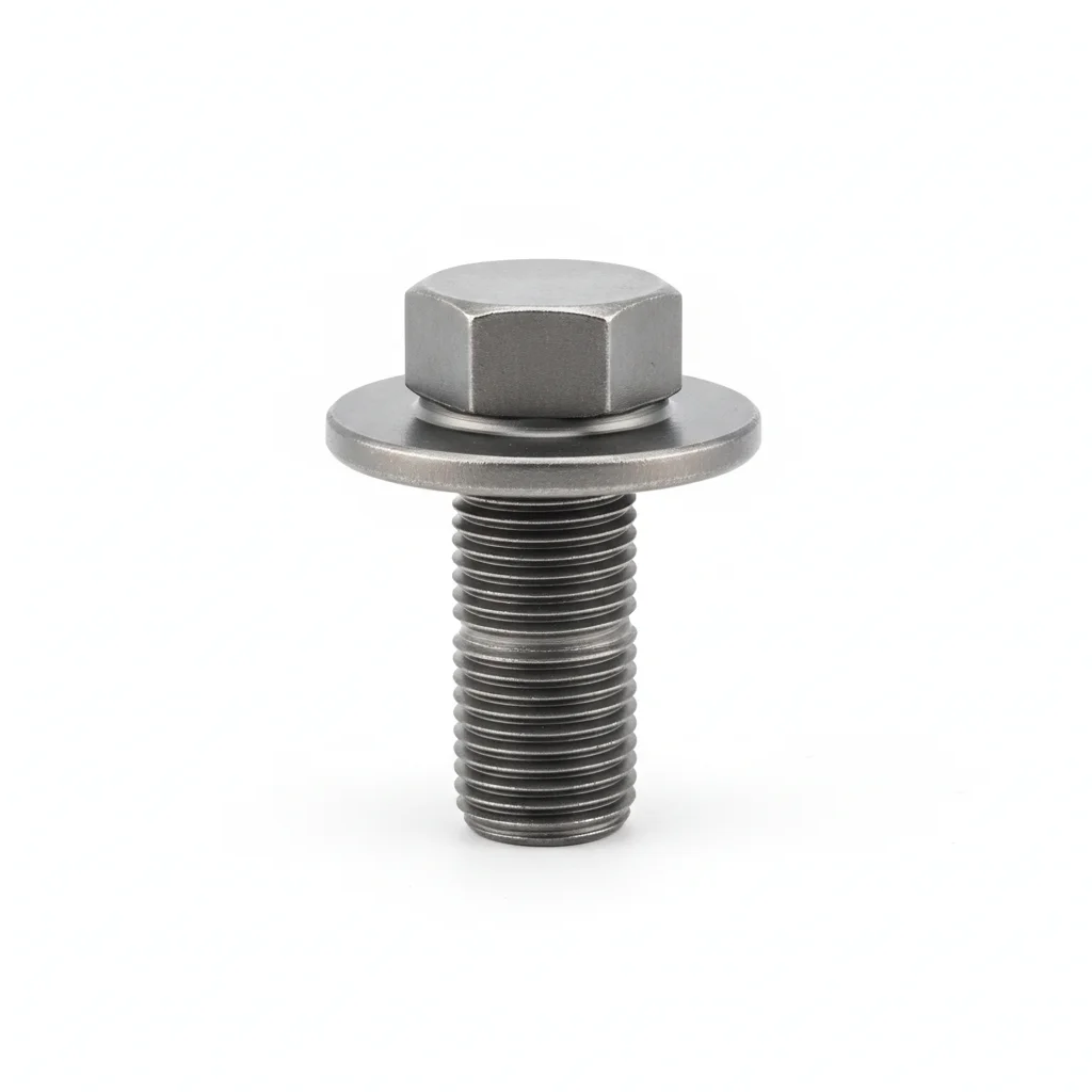
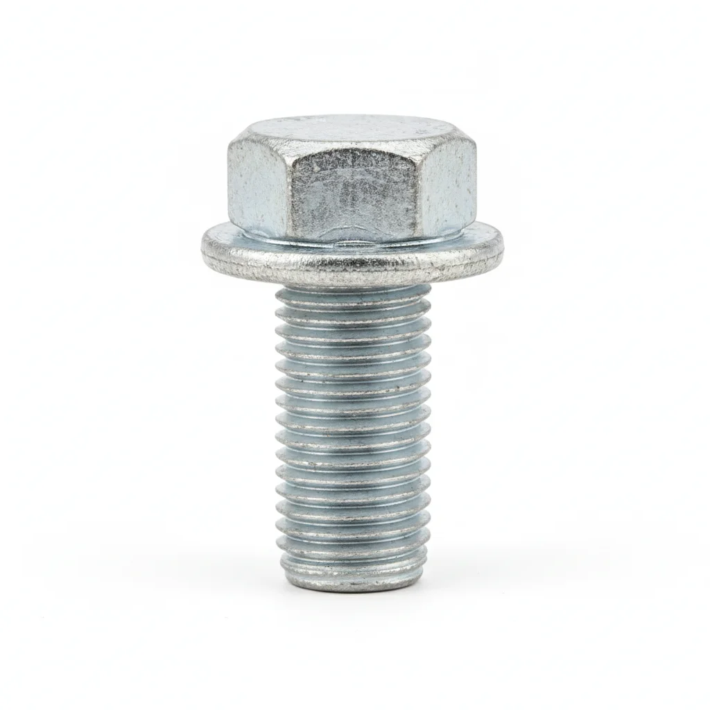
| Grade 10.9 Fan Base Bolt | Grade 8.8 Duct Flange Bolt | |
|---|---|---|
| SPEC | M16-M24 | M8-M10 |
| MATERIAL | 42CrMo | Carbon Steel |
| GRADE | Grade 10.9 Dacromet | Grade 8.8 Hot-Dip Galvanized |
| FINISH | HDG >=55um per ISO 1461 | HDG >=55um per ISO 1461 |
| CORROSION | C3 (ISO 12944-2) | C3 (ISO 12944-2) |
| TEMP | -20°C to +80°C | -20°C to +80°C |
| WEIGHT | ~0.5 kg/piece | ~0.5 kg/piece |
| MOQ | 100 pcs | 100 pcs |
| PACK | VCI paper + carton | VCI paper + carton |
| STD | ISO 898-1, GB/T 3098.1 | ISO 898-1, GB/T 3098.1 |
| USE | Fan base fixing | Duct flange connection |
PROCEDURE
- Clean the fan base and flange contact faces with isopropyl alcohol, ensuring flatness within 0.1mm per 100mm to seat the grade 10.9 bolts evenly.
- Position the base bolt with a spring vibration isolator beneath the foundation; set the isolator's natural frequency below 0.7 times the fan speed to avoid resonance.
- Tighten the M16-M24 bolts in a cross pattern using a calibrated torque wrench, then add a second nut as a jam nut per the double-nut configuration.
- After the fan is operational, measure bearing housing vibration velocity with a vibrometer; confirm it stays below 4.5 mm/s (ISO 14694) before finalizing the installation.
- Mark each bolt with torque seal paint across the head and nut, and log the torque values and vibration readings in the QA record.
COMMON ERRORS
| ✕ WRONG | CONSEQUENCE | ✓ CORRECT |
|---|---|---|
| Installing grade 8.8 bolts on the fan base where grade 10.9 is specified | Under resonance the bolt preload decays stepwise, the fan can shift on its foundation, and the coupling misaligns, reducing bearing life from 50,000h to 5,000h. | Use grade 10.9 bolts (42CrMo, Dacromet) for the fan base and secure them with double nuts; verify the grade marking before assembly. |
| Omitting the spring vibration isolator or selecting one with a natural frequency above 0.7× fan speed | Resonance amplifies bolt impact loads 3-5 times normal, causing preload loss and anchor bolt pullout from concrete. | Choose spring isolators with natural frequency below 0.7× fan operating speed, sized for the fan weight and speed. |
MAINTENANCE
Inspect the fan base bolts at each quarterly maintenance window, re-torquing any bolt that has lost more than 15% of its specified preload. Verify the bearing housing vibration velocity remains below 4.5 mm/s (ISO 14694); if it rises, check bolt tightness and isolator condition. Replace any base bolt showing corrosion beyond the C3 class limits or with pitting depth exceeding 0.3mm.
B · High Temperature / Industrial Exhaust
C4 Harsh per ISO 12944-2
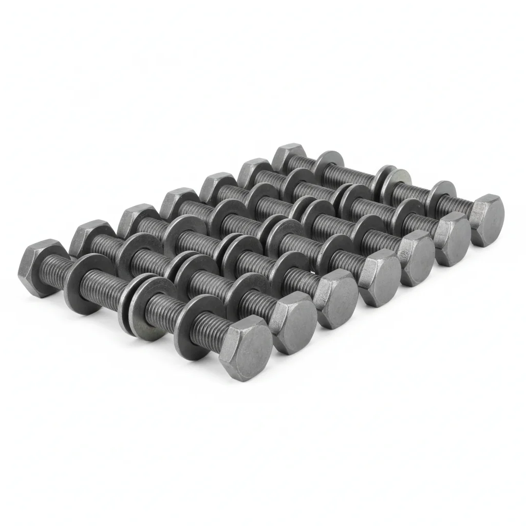
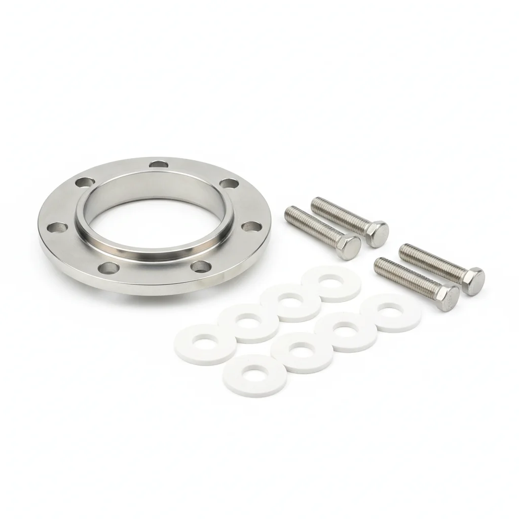
| 304 Stainless Steel Fan Bolt | 304 Duct Flange Bolt + Ceramic Washer | |
|---|---|---|
| SPEC | M16-M24 | M8-M12 |
| MATERIAL | 304 | 304 + Ceramic Fiber |
| GRADE | A2-70 | — |
| FINISH | HDG >=55um per ISO 1461 | HDG >=55um per ISO 1461 |
| CORROSION | C3 (ISO 12944-2) | C3 (ISO 12944-2) |
| TEMP | -20°C to +80°C | -20°C to +80°C |
| WEIGHT | ~0.5 kg/piece | ~0.5 kg/piece |
| MOQ | 100 pcs | 100 pcs |
| PACK | VCI paper + carton | VCI paper + carton |
| STD | ISO 898-1, GB/T 3098.1 | ISO 898-1, GB/T 3098.1 |
| USE | High temperature smoke exhaust fan | >200°C smoke exhaust duct |
PROCEDURE
- Degrease flange faces and bolt threads with acetone to remove oils and particulates; verify surface roughness Ra <3.2um with a profilometer.
- Apply anti-seize compound suitable for the exhaust temperature range to the 304 bolt threads, and seat ceramic washers under the bolt head and nut to prevent galling at high temperature.
- Align flanges within permissible misalignment, then tighten the 304 duct flange bolts in a cross-pattern sequence to the torque specified for A2-70 grade; verify 10% with a calibrated torque wrench and log environmental conditions.
- Pull-test a random 5% sample to 80% of proof load to confirm preload retention; replace any bolt that falls below acceptance threshold.
- Apply weatherproof sealant around exposed bolt heads and nuts where the duct passes through walls or roofs, and attach a corrosion monitoring coupon adjacent to critical joints.
COMMON ERRORS
| ✕ WRONG | CONSEQUENCE | ✓ CORRECT |
|---|---|---|
| Reusing standard zinc-plated carbon steel bolts in the high-temperature exhaust duct | At exhaust temperatures above the zinc coating limit, the coating degrades and the bolt loses corrosion protection, leading to premature pitting and preload loss within the first season of operation. | Select A2-70 304 stainless steel bolts with ceramic washers for this service; verify material grade certificates before installation. |
| Overtorquing 304 bolts to compensate for thermal expansion | Exceeding the specified torque for A2-70 can strip threads or cause stress corrosion cracking at elevated temperatures, leading to sudden joint failure during a thermal cycle. | Tighten to the torque value specified for A2-70 grade using a calibrated wrench; rely on the ceramic washer and proper gasket compression rather than excessive torque. |
MAINTENANCE
Inspect at each overhaul window or seasonally, checking for signs of galling, discoloration, or ceramic washer cracking; re-torque any bolt that has lost more than 15% of specified tension, and replace bolts showing pitting depth greater than 0.3mm or corrosion over 5% of surface area.
Plan C · Explosion-Proof / Clean Room
C5-M Extreme per ISO 12944-2
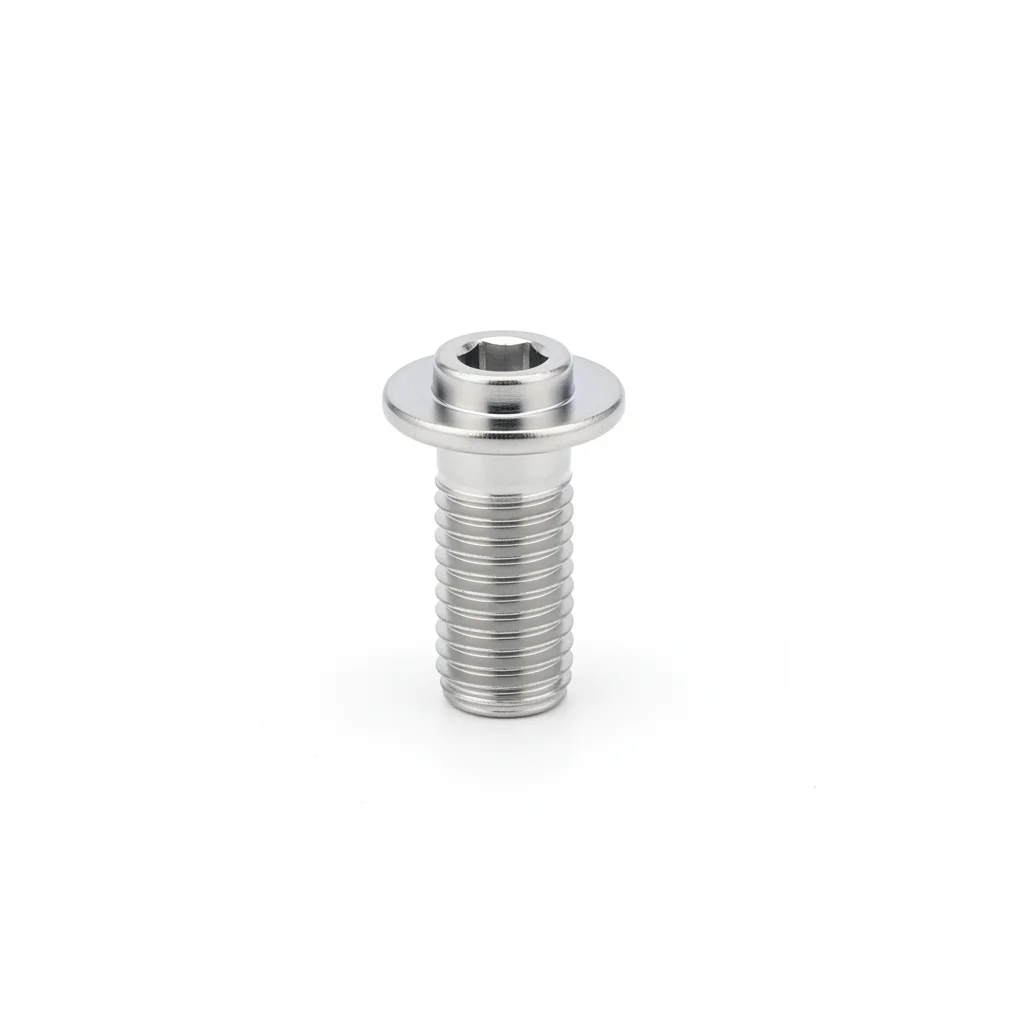
| 304 Stainless Steel Fan Bolt | 304 Duct Flange Bolt + Ceramic Washer | |
|---|---|---|
| SPEC | M16-M24 | M8-M12 |
| MATERIAL | 316L | 316L + Ceramic Fiber |
| GRADE | A2-70 | — |
| FINISH | HDG >=55um per ISO 1461 | HDG >=55um per ISO 1461 |
| CORROSION | C3 (ISO 12944-2) | C3 (ISO 12944-2) |
| TEMP | -20°C to +80°C | -20°C to +80°C |
| WEIGHT | ~0.5 kg/piece | ~0.5 kg/piece |
| MOQ | 100 pcs | 100 pcs |
| PACK | VCI paper + carton | VCI paper + carton |
| STD | ISO 898-1, GB/T 3098.1 | ISO 898-1, GB/T 3098.1 |
| USE | Extreme conditions / Maximum protection | Extreme conditions / Maximum protection |
PROCEDURE
- Degrease with MEK solvent and verify surface roughness Ra <1.6um on flange faces and bolt threads to ensure proper seating in cleanroom or explosion-proof zones.
- Apply marine-grade anti-seize compound rated for the service temperature range and use PTFE-encapsulated washers to isolate the 316L bolts from the flange material, preventing galvanic corrosion.
- Align flanges within 0.3mm and tension the 316L bolts using a hydraulic tensioner to achieve the target preload for A2-70 grade; perform PMI verification on a 10% sample to confirm alloy composition.
- Conduct dye penetrant testing on 10% of the installed bolts to detect any surface cracks; replace any bolt showing crack indications before commissioning.
- Apply protective sealant to all exposed threads and install permanent condition monitoring instrumentation to track preload and corrosion in the extreme environment; file compliance documentation for regulatory audit.
COMMON ERRORS
| ✕ WRONG | CONSEQUENCE | ✓ CORRECT |
|---|---|---|
| Using 304 stainless steel bolts in a chloride-rich cleanroom or explosion-proof area | 304 is susceptible to pitting and stress corrosion cracking in chloride environments, reducing fastener life from the intended design life to under one year and creating a safety hazard in explosion-proof zones. | Specify 316L stainless steel bolts (A2-70 or higher) for extreme conditions; verify material certification and surface finish per specification. |
| Skipping anti-static grounding when installing fasteners in an explosion-proof fan assembly | Without proper grounding, static charge can accumulate and discharge, igniting flammable atmospheres; loose or corroded fasteners break the grounding path. | Ensure the fan and duct system includes anti-static bonding across bolted joints; use conductive washers or grounding straps as specified, and verify continuity after installation. |
MAINTENANCE
Inspect at each overhaul window or more frequently in corrosive atmospheres, using the permanent monitoring instrumentation to track preload; re-torque any bolt that has lost more than 15% of specified tension, and replace any bolt with pitting depth greater than 0.3mm or corrosion affecting more than 5% of surface area.
REFERENCED STANDARDS
References
SUPPLIER CAPABILITY
Quality, Delivery & Customization
Quality Control
- ✓MTC material certificates with every batch
- ✓Key parts sampled for hardness/salt spray/torque coefficient
- ✓100% inspection or AQL sampling before shipment
Delivery
- ✓Standard parts made to order: 7-15 days
- ✓Custom parts: 25-45 days
- ✓FOB/CIF/DDP supported
Customization
- ✓Drawing review and material matching
- ✓Non-standard sizes/heads/threads
- ✓Small-batch prototyping supported
Certification
- ✓Material certificates (MTC)
- ✓Spectrographic analysis reports
- ✓Salt spray test reports (on request)
MOQ: No MOQ for standard parts; custom parts assessed by process complexity
FAQ
Frequently Asked Questions
RELATED READING
Keep Reading & Next Step
BEYOND TECHNICAL SPECS
Finding the right factory, controlling quality, delivering on time — that's the real challenge. We cover fasteners, rubber, plastics, industrial textiles. One team, end to end.
SEE CAPABILITIES →