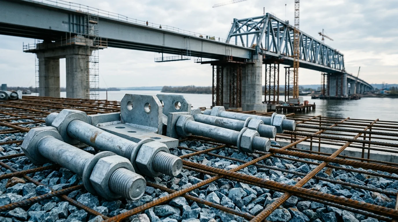
Grounding Rod Connector Hardware for Landscape Lighting
Landscape lighting grounding failures usually appear at the rod-to-wire joint, clamp or mixed-metal contact point before anyone checks the rod body. Material choice must be tied to soil exposure and connector compatibility
RISK AUDIT // ENGINEERING DIAGNOSIS
Procurement Pitfall Guide
"Common grounding failures in landscape lighting start at the rod-to-wire joint, not the rod body."
QC-AUDIT // REV.5
SCALE 1:1 · 03 ITEMS
RISK-01
Copper-Clad Steel Grounding Rod Corrosion Perforation in Acidic Soil
Corrective Measures
RISK-02
Stress Corrosion Cracking of Pure Copper Grounding Rods in High-Chloride Soil
Corrective Measures
RISK-03
Crevice Corrosion and Pitting of Stainless Steel Grounding Rods in Acidic Clay
Corrective Measures
FIELD-SPECIFIC INSIGHT
Do Not Specify the Rod Without the Connector
A supplier sample such as nVent ERICO shows that grounding rods are sold with material, coating and listing language. For municipal landscape lighting, the purchasing risk is incomplete: the rod, clamp, conductor and installation method need to be specified together
WHAT TO CHECK
- 1Match the rod material to the connector and conductor; mixed metals can move the corrosion point to the joint
- 2Ask whether the clamp, lug or welded connection is approved for the rod material being offered
- 3Separate temporary lighting, road medians and coastal landscape zones because soil moisture and maintenance access differ
- 4Require supplier documentation for rod listing, coating description and compatible connector family
| Check | Why it matters | What to specify |
|---|---|---|
| Rod-to-wire joint | The grounding path depends on the connection, not only the buried rod | Clamp, lug, welding method or connector family; include conductor material |
| Soil exposure | Wet soil, fertilizer, deicing salt and coastal air change corrosion risk at the joint | Installation zone, drainage condition and maintenance access |
| Supplier evidence | Grounding components need listing and compatibility evidence, not just a material name | Rod listing, coating description, connector compatibility and test document |
The nVent page is used as a supplier sample, not a universal design rule. Final grounding design should follow local electrical code and project drawings
Evidence level: source-page-only
INDUSTRY TECH REFERENCE
Grounding Rod Selection: Which Alloy for Each of Four Soil Tiers
A landscape pole is a natural air terminal, and each pole needs its own independent grounding. Pick the rod alloy from the on-site soil first — neutral, acidic (pH < 5), high resistivity (> 500 Ω·m) and coastal saline-alkali — each tier comes with a recommended and an alternative option. Match the soil test report before you order.
| Soil condition | Recommended | Alternative |
|---|---|---|
| Neutral soil | Copper-clad steel (copper layer ≥ 0.25 mm) | Hot-dip galvanized steel |
| Acidic soil (pH < 5) | Copper-clad steel (copper layer ≥ 0.5 mm) | Stainless steel rod |
| High resistivity (> 500 Ω·m) | Copper-clad steel + resistance-reducing agent | Deep well + ionic earth electrode |
| Coastal saline-alkali soil | Stainless steel rod | Pure copper rod |
The soil tiers and the copper-layer thickness tiers (≥ 0.25 mm / ≥ 0.5 mm) follow the common practice of the JGJ/T 16 family (electrical design for civil buildings) and GB 50057 (lightning protection design). No magnitude-estimate figures are used.
INDUSTRY TECH REFERENCE
Acid-Soil Failure Chain: From Copper-Layer Perforation to Resistance Over 10 Ω
A 0.25 mm copper layer that passes acceptance in neutral soil is a different story in acidic soil. The chain starts with a thinning copper layer and ends with grounding resistance past 10 Ω and a degraded lightning path — every step has a checkable interception point.
- 1Acidic soil (pH < 5) attacks the copper layer faster: the selection table raises the copper-layer floor for this tier from ≥ 0.25 mm to ≥ 0.5 mm
- 2The thinnest point of the copper layer perforates first and exposes the steel core — the exposed core and the copper layer form a galvanic couple in which steel is the anode, so corrosion speeds up (galvanic isolation is a cross-verified finding in the archive)
- 3The steel core corrodes → effective cross-section shrinks → grounding resistance climbs
- 4Crossing the acceptance line: in the TT system each pole is grounded independently, with grounding resistance required to be ≤ 10 Ω (the JGJ/T 16 family reference value); above it, the grounding is judged failed
- 5Consequence and interception: the landscape pole is an air terminal, and a degraded grounding path weakens lightning-current discharge; interception points — put the ≥ 0.5 mm copper layer into the inquiry for acidic soil, crimp the conductor hydraulically instead of soldering, and keep one independent rod per pole
The ≤ 10 Ω grounding-resistance value follows the JGJ/T 16 family (electrical design for civil buildings); the two copper-layer thickness tiers (≥ 0.25 mm / ≥ 0.5 mm) follow the same common practice of the JGJ/T 16 family and GB 50057 (lightning protection design). No magnitude-estimate figures are used.
INDUSTRY TECH REFERENCE
The Conductor Three-Pack: ≥ 16 mm², Hydraulic Crimping, Heat-Shrink Seal
However deep the rod is buried, the current still has to travel up the conductor into the pole terminal. Only three things matter: copper cross-section, the crimping method and the seal — each with hard numbers.
- Cross-section: the conductor from the rod to the pole terminal is copper core ≥ 16 mm²; order rod and conductor as one matched set, not as a small separate connector item
- Method: hydraulic crimping of the copper terminal, soldering banned — tin melts at 232 °C, and a lightning surge can melt a soldered joint in an instant, so the joint fails first under a strike
- Seal: heat-shrink sleeve plus waterproof sealant over the crimp — a wet joint is a common source of climbing grounding resistance
- Configuration: one rod per pole, independently grounded and not interconnected (TT system) — wire pole by pole, and do not share one rod across two poles to save material
- When soil makes compliance hard (sand, rock, ≤ 10 Ω out of reach): follow the high-resistivity tier and add a resistance-reducing agent, or switch to a deep well + ionic earth electrode — do not compensate with an over-long conductor or by sharing rods
The ≥ 16 mm² conductor and the ≤ 10 Ω grounding-resistance value follow the common practice of the JGJ/T 16 family (electrical design for civil buildings) and GB 50057 (lightning protection design). No magnitude-estimate figures are used.
INDUSTRY TECH REFERENCE
One System, One Alloy: The Galvanic Ledger of Copper-Clad vs Pure Copper
Coastal saline-alkali soil takes stainless or pure copper; neutral soil takes copper-clad steel — pick the one alloy that fits the soil. Mixing copper-clad and pure copper in one grounding system puts the steel core in the anode position.
- Galvanic direction: when copper-clad steel (steel core) and pure copper are connected directly, steel is the anode and copper the cathode — in this couple the steel side corrodes first (galvanic isolation is a cross-verified finding across the archive)
- What mixing costs: the steel core corrodes faster, the effective section shrinks and grounding resistance climbs — the alloy system is broken and the failure point moves from the soil to the rod-to-rod joint
- The tier precedent: saline-alkali coastal soil specifies stainless steel rods as the tier, with pure copper as the alternative — one closed tier per alloy family, no cross-tier mixing
- Ordering basis: pack rod, conductor and connector into one alloy family on the inquiry, state the copper-layer tier and the crimping method, and avoid an assembled quote that ends up as a mixed-metal system
No magnitude-estimate figures are used.
INDUSTRY TECH REFERENCE
Two References for Grounding Acceptance: Lightning Protection and Electrical Earthing
The acceptance basis for landscape-pole grounding falls mostly on two standards — match the numbers first, then the values; navigation only, with acceptance values taken from the current texts.
The listed standards are for navigation only, without reproducing clauses: GB 50057 (lightning protection design) and the JGJ/T 16 family (electrical design for civil buildings — TT system and ≤ 10 Ω grounding resistance). No magnitude-estimate figures are used.
PLAN COMPARISON
Three-Plan Core Parameter Comparison
Compare row by row. Click column headers to jump to plan details.
| A · Plan A · Copper-Clad Steel Standard Grounding Rod | B · Plan B · Pure Copper Heavy-Duty Grounding Rod | C · Plan C · 304 Stainless Steel Extreme Grounding Rod | |
|---|---|---|---|
| 1. COPPER-CLAD STEEL GROUNDING ROD | |||
| SPEC | φ14.2×2.5m, copper layer ≥0.254mm, tensile strength ≥580MPa | φ16×3.0m, T2 pure copper, conductivity ≥99.9% IACS | φ20×3.5m, 304 stainless steel integral forging |
| MATERIAL | Copper | T2 Pure Copper | 304 Stainless Steel |
| FINISH | HDG >=55um per ISO 1461 | HDG >=55um per ISO 1461 | HDG >=55um per ISO 1461 |
| 2. GROUNDING CONNECTOR | |||
| SPEC | Exothermic welding mold + welding flux, connection resistance <0.5mΩ | Ag-Cu solder, melting point 780°C, reliable connection | Inconel 625 precision casting, corrosion and high temperature resistant |
| FINISH | HDG >=55um per ISO 1461 | HDG >=55um per ISO 1461 | HDG >=55um per ISO 1461 |
| 3. RESISTANCE REDUCING AGENT | |||
| SPEC | Physical resistance reducing agent, dosage 25kg/rod, reduces grounding resistance by 30-50% | Chemical resistance reducing agent, dosage 40kg/rod, reduces grounding resistance by 50-70% | Long-lasting type, effective for 10 years, continuously releases electrolyte |
| FINISH | HDG >=55um per ISO 1461 | HDG >=55um per ISO 1461 | HDG >=55um per ISO 1461 |
| 4. TEST WELL | |||
| SPEC | PVC material, φ200×300mm, convenient for periodic inspection | 304 stainless steel, φ250×400mm, corrosion resistant | RFID chip, records installation time and inspection records |
| MATERIAL | PVC | 304 Stainless Steel | EPDM Rubber |
| FINISH | HDG >=55um per ISO 1461 | HDG >=55um per ISO 1461 | HDG >=55um per ISO 1461 |
| 5. SIGN PLATE | |||
| SPEC | Reflective film, marking grounding number and resistance value | Asphalt paint + fiberglass cloth, double protection | Hydraulic drive driver, avoids damaging the rod body |
| FINISH | HDG >=55um per ISO 1461 | HDG >=55um per ISO 1461 | HDG >=55um per ISO 1461 |
SELECTION GUIDE
How to Choose a Grounding Rod Solution Based on Soil Conditions?
| Operating condition | Recommended option | Key basis |
|---|---|---|
| Dry Soil / Standard Landscape Lighting | Plan A · Copper-Clad Steel standard rod (copper layer ≥0.254mm) + hot-dip galvanized connectors | C3 per ISO 12944-2; UL 467 minimum copper layer 0.254mm (10mil); exothermic welding keeps connection resistance <0.5mΩ; design life 15-25 years |
| Moist Soil / Coastal / Key Landscape Nodes | Plan B · Pure Copper heavy-duty rod (T2, ≥99.9% IACS) + silver solder connector | C4 Harsh per ISO 12944-2; 15% higher conductivity than copper-clad steel; 25-40 year design life; Ag-Cu solder melting point 780°C |
| Highly Corrosive Soil / Chemical Industrial Park / Ultra-Long Life | Plan C · 304 Stainless Steel extreme rod (integral forging) + Inconel 625 connector | C5-M Extreme per ISO 12944-2; for pH 3.5-5.0 acidic clay with resistivity <20Ω·m; acid and alkali corrosion resistant |
Plan A · Copper-Clad Steel Standard Grounding Rod
C3 standard per ISO 12944-2 for dry soil landscape lighting
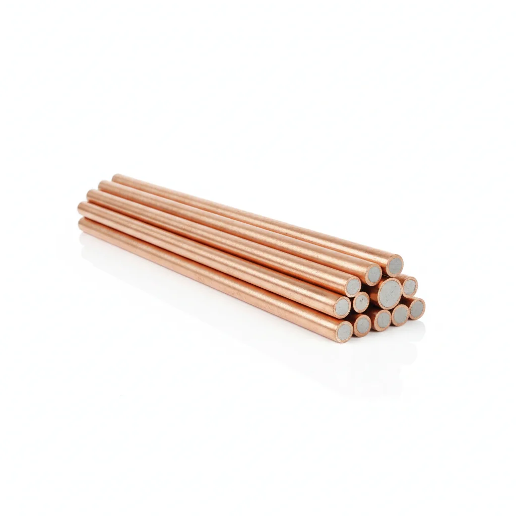
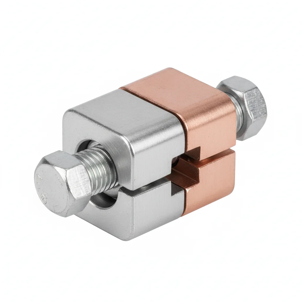
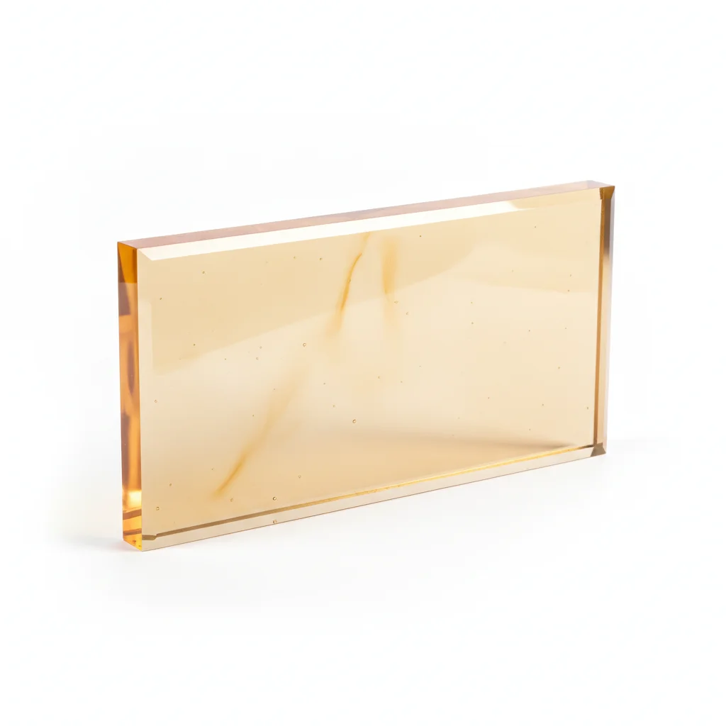
| Copper-Clad Steel Grounding Rod | Grounding Connector | Resistance Reducing Agent | Test Well | Sign Plate | |
|---|---|---|---|---|---|
| SPEC | φ14.2×2.5m, copper layer ≥0.254mm, tensile strength ≥580MPa | Exothermic welding mold + welding flux, connection resistance <0.5mΩ | Physical resistance reducing agent, dosage 25kg/rod, reduces grounding resistance by 30-50% | PVC material, φ200×300mm, convenient for periodic inspection | Reflective film, marking grounding number and resistance value |
| MATERIAL | Copper | — | — | PVC | — |
| GRADE | — | — | — | — | — |
| FINISH | HDG >=55um per ISO 1461 | HDG >=55um per ISO 1461 | HDG >=55um per ISO 1461 | HDG >=55um per ISO 1461 | HDG >=55um per ISO 1461 |
| CORROSION | C3 (ISO 12944-2) | C3 (ISO 12944-2) | C3 (ISO 12944-2) | C3 (ISO 12944-2) | C3 (ISO 12944-2) |
| TEMP | -20°C to +80°C | -20°C to +80°C | -20°C to +80°C | -20°C to +80°C | -20°C to +80°C |
| WEIGHT | ~0.5 kg/piece | ~0.5 kg/piece | ~0.5 kg/piece | ~0.5 kg/piece | ~0.5 kg/piece |
| MOQ | 100 pcs | 100 pcs | 100 pcs | 100 pcs | 100 pcs |
| PACK | VCI paper + carton | VCI paper + carton | VCI paper + carton | VCI paper + carton | VCI paper + carton |
| STD | ISO 898-1, GB/T 3098.1 | ISO 898-1, GB/T 3098.1 | ISO 898-1, GB/T 3098.1 | ISO 898-1, GB/T 3098.1 | ISO 898-1, GB/T 3098.1 |
| USE | Tensile strength ≥580MPa | Connection resistance <0.5mΩ | Reduces grounding resistance by 30-50% | Convenient for periodic inspection | Marking grounding number and resistance value |
PROCEDURE
- Drive the copper-clad steel rod (φ14.2×2.5m, copper layer ≥0.254mm) vertically into undisturbed soil, leaving ≥150mm above grade for connector access.
- Clean the rod surface and conductor contact area with a wire brush to remove oxide film before attaching the grounding connector.
- Install the exothermic welding mold around the rod and conductor, ensuring a snug fit; ignite the welding flux to form a molecular bond with connection resistance <0.5mΩ.
- After weld cools, chip off slag and inspect for voids; apply cold galvanizing compound to the weld zone to restore corrosion protection.
- Backfill the excavation with native soil, mixing in the resistance reducing agent at 25kg/rod to lower soil resistivity by 30-50%.
- Place the PVC test well (φ200×300mm) over the connection point and install the reflective sign plate marking the grounding number and resistance value.
COMMON ERRORS
| ✕ WRONG | CONSEQUENCE | ✓ CORRECT |
|---|---|---|
| Using an uncoated steel clamp directly on the copper-clad rod in wet soil | Galvanic corrosion at the bimetallic joint accelerates copper loss, exposing the steel core within 5-10 years and raising resistance above safe limits. | Specify hot-dip galvanized connectors (HDG ≥55um per ISO 1461) or exothermic welding to eliminate the bimetallic interface. |
| Burying the rod in dry, rocky soil without adding resistance reducing agent | Grounding resistance stays above the design threshold, leaving the luminaire without an effective fault path during lightning or leakage. | Treat the soil with the physical resistance reducing agent (25kg/rod) to cut resistance by 30-50% and improve electrode contact. |
MAINTENANCE
At each seasonal inspection before the rainy period, open the test well to check the connection for corrosion or loosening; measure grounding resistance and record trends. Excavate 1-2 rods every 5 years to verify copper layer thickness remains ≥0.254mm per UL 467 guidelines; replace any rod showing steel core exposure or resistance exceeding design value in consecutive tests.
Plan B · Pure Copper Heavy-Duty Grounding Rod
C4 Harsh per ISO 12944-2
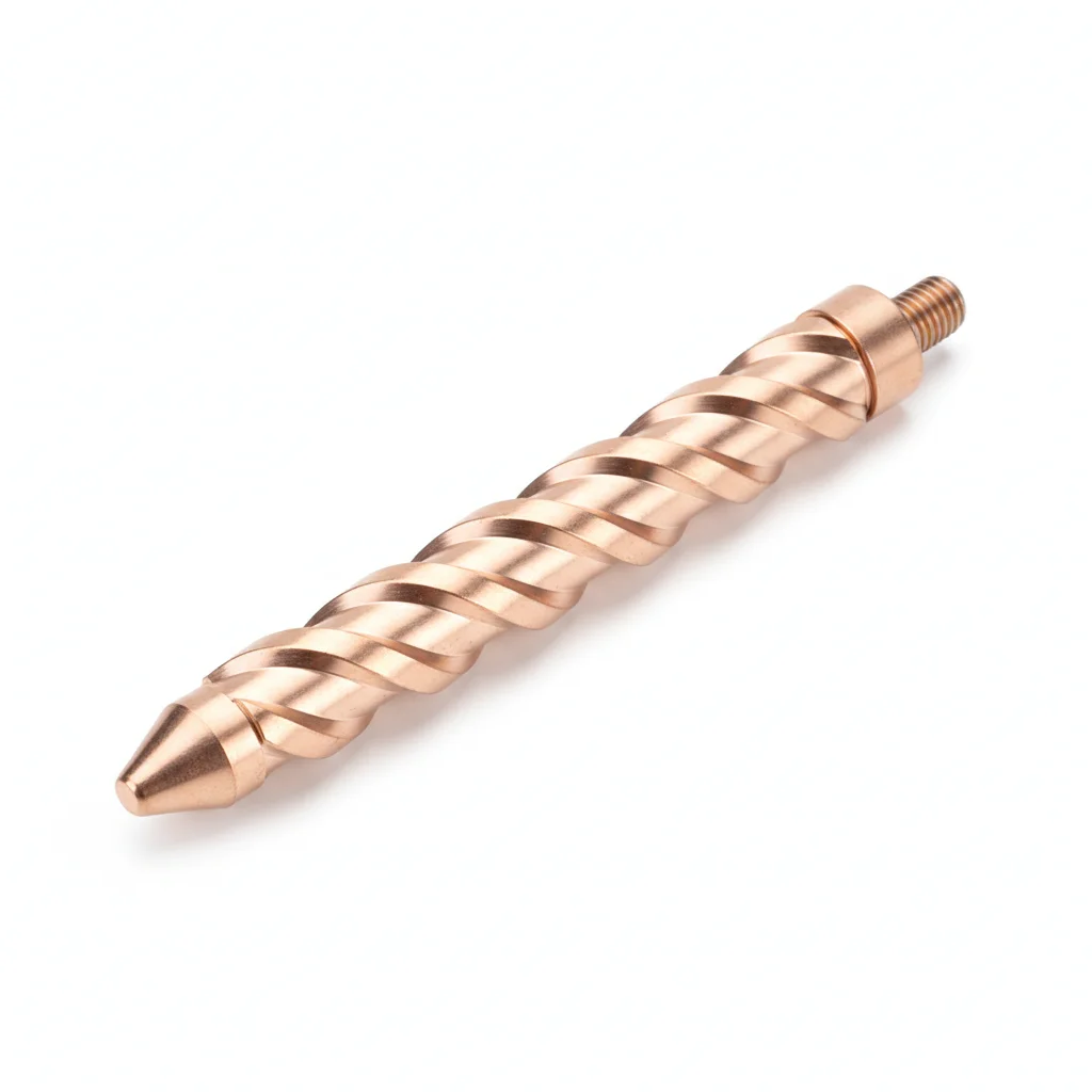
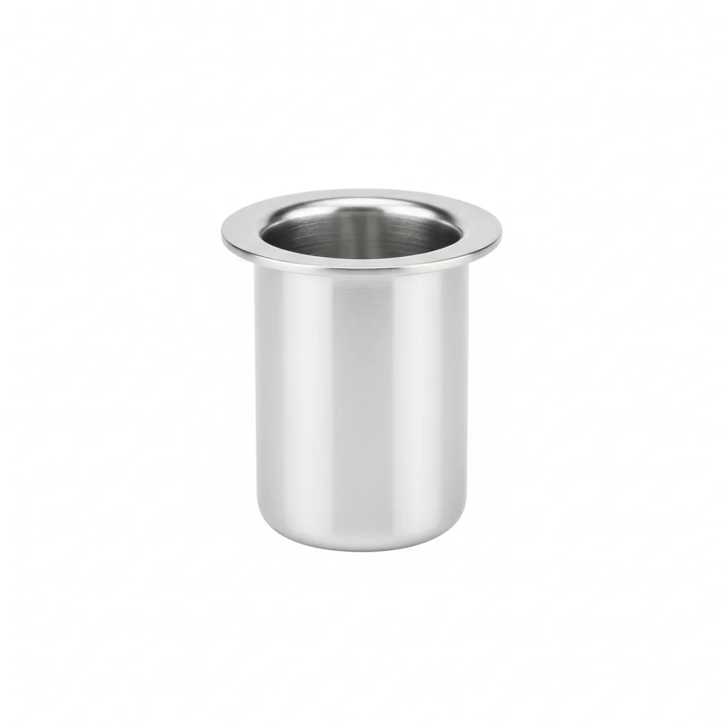
| Pure Copper Grounding Rod | Silver Solder Connector | High-Efficiency Resistance Reducing Agent | Test Well | Anti-Corrosion Coating | |
|---|---|---|---|---|---|
| SPEC | φ16×3.0m, T2 pure copper, conductivity ≥99.9% IACS | Ag-Cu solder, melting point 780°C, reliable connection | Chemical resistance reducing agent, dosage 40kg/rod, reduces grounding resistance by 50-70% | 304 stainless steel, φ250×400mm, corrosion resistant | Asphalt paint + fiberglass cloth, double protection |
| MATERIAL | T2 Pure Copper | — | — | 304 Stainless Steel | — |
| GRADE | — | — | — | — | — |
| FINISH | HDG >=55um per ISO 1461 | HDG >=55um per ISO 1461 | HDG >=55um per ISO 1461 | HDG >=55um per ISO 1461 | HDG >=55um per ISO 1461 |
| CORROSION | C3 (ISO 12944-2) | C3 (ISO 12944-2) | C3 (ISO 12944-2) | C3 (ISO 12944-2) | C3 (ISO 12944-2) |
| TEMP | -20°C to +80°C | -20°C to +80°C | -20°C to +80°C | -20°C to +80°C | -20°C to +80°C |
| WEIGHT | ~0.5 kg/piece | ~0.5 kg/piece | ~0.5 kg/piece | ~0.5 kg/piece | ~0.5 kg/piece |
| MOQ | 100 pcs | 100 pcs | 100 pcs | 100 pcs | 100 pcs |
| PACK | VCI paper + carton | VCI paper + carton | VCI paper + carton | VCI paper + carton | VCI paper + carton |
| STD | ISO 898-1, GB/T 3098.1 | ISO 898-1, GB/T 3098.1 | ISO 898-1, GB/T 3098.1 | ISO 898-1, GB/T 3098.1 | ISO 898-1, GB/T 3098.1 |
| USE | Conductivity ≥99.9% IACS | Reliable connection | Reduces grounding resistance by 50-70% | Corrosion resistant | Double protection |
PROCEDURE
- Degrease the pure copper rod and silver solder connector surfaces with acetone to remove any film before assembly.
- Set the T2 copper rod (φ16×3.0m) vertically in the excavated hole, ensuring the top is at the required depth below grade.
- Apply the high-efficiency chemical resistance reducing agent (40kg/rod) around the rod in layers, tamping each lift to eliminate voids.
- Connect the silver solder connector (Ag-Cu, melting point 780°C) using a torch, heating until solder flows completely around the joint.
- Install the 304 stainless steel test well (φ250×400mm) over the connection point, backfilling and compacting the surrounding soil.
- Coat the exposed connection and test well rim with the asphalt paint + fiberglass cloth anti-corrosion layer for double protection.
COMMON ERRORS
| ✕ WRONG | CONSEQUENCE | ✓ CORRECT |
|---|---|---|
| Using a copper-clad steel clamp on a pure copper rod in coastal soil. | Galvanic corrosion at the bimetallic contact accelerates metal loss, and the joint resistance rises above the 0.5mΩ limit within a few seasons. | Use the Ag-Cu silver solder connector (melting point 780°C) that matches the T2 pure copper rod to keep the joint homogeneous. |
| Backfilling the rod without installing the 304 stainless steel test well for inspection access. | The silver solder joint cannot be re-torqued or inspected, and corrosion at the connection goes undetected until the lighting ground fails. | Place the 304 stainless steel test well (φ250×400mm) over the joint so the connection can be checked and maintained without excavating. |
MAINTENANCE
Check the silver solder joint and test well condition at each seasonal maintenance cycle, especially after storm surges or coastal flooding; verify the joint resistance stays below 0.5mΩ and re-apply the asphalt-fiberglass anti-corrosion coating whenever the existing layer shows cracking or disbondment.
Plan C · 304 Stainless Steel Extreme Grounding Rod
C5-M Extreme per ISO 12944-2
| Grounding Rod | Special Alloy Connector | Ion Slow-Release Resistance Reducing Agent | Smart Monitoring Tag | Dedicated Installation Tool | |
|---|---|---|---|---|---|
| SPEC | φ20×3.5m, 304 stainless steel integral forging | Inconel 625 precision casting, corrosion and high temperature resistant | Long-lasting type, effective for 10 years, continuously releases electrolyte | RFID chip, records installation time and inspection records | Hydraulic drive driver, avoids damaging the rod body |
| MATERIAL | 304 Stainless Steel | — | — | EPDM Rubber | — |
| GRADE | — | — | — | — | — |
| FINISH | HDG >=55um per ISO 1461 | HDG >=55um per ISO 1461 | HDG >=55um per ISO 1461 | HDG >=55um per ISO 1461 | HDG >=55um per ISO 1461 |
| CORROSION | C3 (ISO 12944-2) | C3 (ISO 12944-2) | C3 (ISO 12944-2) | Not applicable (polymer) | C3 (ISO 12944-2) |
| TEMP | -20°C to +80°C | -20°C to +80°C | -20°C to +80°C | -20°C to +80°C | -20°C to +80°C |
| WEIGHT | ~0.5 kg/piece | ~0.5 kg/piece | ~0.5 kg/piece | ~0.5 kg/piece | ~0.5 kg/piece |
| MOQ | 100 pcs | 100 pcs | 100 pcs | 100 pcs | 100 pcs |
| PACK | VCI paper + carton | VCI paper + carton | VCI paper + carton | VCI paper + carton | VCI paper + carton |
| STD | ISO 898-1, GB/T 3098.1 | ISO 898-1, GB/T 3098.1 | ISO 898-1, GB/T 3098.1 | ISO 898-1, GB/T 3098.1 | ISO 898-1, GB/T 3098.1 |
| USE | 304 stainless steel integral forging | Corrosion and high temperature resistant | Continuously releases electrolyte | Records installation time and inspection records | Avoids damaging the rod body |
PROCEDURE
- Clean the 304 stainless steel rod (φ20×3.5m) and Inconel 625 connector mating surfaces with a solvent to remove all organic contamination.
- Lower the rod into the hole and align the special alloy connector, using the dedicated hydraulic drive driver to seat it without damaging the rod body.
- Torque the connector to the specified value using a calibrated wrench, following a cross-pattern sequence to ensure even clamping.
- Apply the long-lasting ion slow-release resistance reducing agent around the rod, filling the annulus completely to the design height.
- Attach the smart monitoring tag (RFID) to the rod head and program it with the installation date and initial resistance reading.
- Backfill with the excavated soil or specified low-resistivity backfill, compacting in layers while avoiding sharp stones that could scratch the rod.
COMMON ERRORS
| ✕ WRONG | CONSEQUENCE | ✓ CORRECT |
|---|---|---|
| Hammering the 304 stainless steel rod directly with a sledgehammer instead of using the hydraulic driver. | The rod body can bend or crack, and the forged integral structure may develop stress points that lead to premature failure in acidic clay. | Use the dedicated hydraulic drive driver to advance the φ20×3.5m rod, keeping the rod straight and the surface unmarred. |
| Connecting the copper grounding conductor directly to the stainless steel rod with a standard clamp. | Crevice corrosion and galvanic attack form at the mixed-metal joint, creating a high-resistance point that defeats the grounding path. | Use the Inconel 625 special alloy connector, which is engineered for corrosion and high-temperature resistance in chemical park soils. |
MAINTENANCE
At each overhaul window, read the smart monitoring tag (RFID) to review the installation history, then test the grounding resistance and inspect the rod-to-connector interface for any signs of pitting or crevice corrosion; replace the ion slow-release resistance reducing agent when its 10-year effectiveness period expires.
REFERENCED STANDARDS
Technical Basis and Reference Standards
Technical Code for Detection of Lightning Protection Devices in Buildings
Safety Requirements for Floodlighting LuminairesProtection against lightning - Part 3: Physical damage to structures and life hazard
Code for Design of Lightning Protection of BuildingsCode for Design of Lightning Protection of Buildings
Lightning ProtectionGrounding of AC Electrical Installations
Grounding and Equipotential BondingStandard for Grounding and Bonding Equipment
SUPPLIER CAPABILITY
Quality, Delivery & Customization
Quality Control
- ✓MTC material certificates with every batch
- ✓Key parts sampled for hardness/salt spray/torque coefficient
- ✓100% inspection or AQL sampling before shipment
Delivery
- ✓Standard parts made to order: 7-15 days
- ✓Custom parts: 25-45 days
- ✓FOB/CIF/DDP supported
Customization
- ✓Drawing review and material matching
- ✓Non-standard sizes/heads/threads
- ✓Small-batch prototyping supported
Certification
- ✓Material certificates (MTC)
- ✓Spectrographic analysis reports
- ✓Salt spray test reports (on request)
MOQ: No MOQ for standard parts; custom parts assessed by process complexity
FAQ
Frequently Asked Questions
RELATED READING
Keep Reading & Next Step
BEYOND TECHNICAL SPECS
Finding the right factory, controlling quality, delivering on time — that's the real challenge. We cover fasteners, rubber, plastics, industrial textiles. One team, end to end.
SEE CAPABILITIES →