
Grounding Hardware: Copper-Clad vs Galvanized Steel
Grounding system performance depends on material choice for rods and connectors. Copper-clad steel resists corrosion in acidic soils, while galvanized steel suits neutral soils. Selection must consider soil resistivity, pH, and IEEE 80 grounding resistance targets
RISK AUDIT // ENGINEERING DIAGNOSIS
Procurement Pitfall Avoidance Guide
"In the field, grounding failures often stem from material and installation oversights."
QC-AUDIT // REV.5
SCALE 1:1 · 03 ITEMS
RISK-01
Grounding electrode corrosion leads to year by year increasing grounding resistance
Corrective Measures
RISK-02
Grounding resistance exceeds standard in high resistivity soil
Corrective Measures
RISK-03
Unstable quality of exothermic welding joints leads to grounding grid open circuit
Corrective Measures
FIELD-SPECIFIC INSIGHT
Material Selection Checklist for Grounding Electrodes
Grounding electrode material choice directly impacts long-term grounding resistance stability. The key differentiator is corrosion rate in site-specific soil conditions, not just initial conductivity
WHAT TO CHECK
- 1Copper-clad steel resists corrosion in acidic soil (pH<5) but requires verification of copper layer thickness per ASTM B227
- 2Galvanized steel is suitable for neutral soil (pH 6-8) but corrodes rapidly in acidic or alkaline conditions, increasing grounding resistance over time
- 3Exothermic welding joints must be inspected for moisture and proper powder ratio; defect rates can be significant if not controlled
- 4In high resistivity soil, deep well grounding or ion grounding rods may be needed regardless of material choice
| Check | Why it matters | What to specify |
|---|---|---|
| Soil resistivity measurement | Determines required grounding electrode length and number; affects material selection | Specify measurement method (Wenner 4-pin) and seasonal correction factor per IEEE 81 |
| Soil pH and corrosivity | Acidic soil accelerates corrosion of galvanized steel; copper-clad steel required | Specify minimum copper layer thickness and test certificate per ASTM B227 |
| Exothermic welding joint quality | Defective joints reduce cross-section and can open under fault current | Specify visual inspection and pull test per IEEE 837 |
| Grounding resistance target | Substation target per GB 50065; transmission line target; affects number of rods | Specify design target and acceptance test under dry season conditions |
All material and joint specifications must be verified with mill certificates and site test reports. No substitute for site-specific soil analysis
Evidence level: standard-backed
INDUSTRY TECH REFERENCE
A Grounding Rod Cores Out: Why Resistance Climbs Year by Year
Example: a copper-clad steel ground rod in acidic soil (pH<5) with stray current.
- 1Copper-clad rods carry a copper layer ≥0.25 mm (magnitude estimate) — in acidic soil with stray current, the copper layer pits through first
- 2The steel core is exposed, forming a galvanic pair with steel as the anode — corrosion accelerates and the rod cores out over the years
- 3With the core gone the effective rod length shrinks and ground resistance climbs from ≤0.5 Ω (GB 50065 substation target)
- 4Higher resistance → poor lightning-current discharge → risk of back-flash and secondary-equipment potential rise — prevent core-out with the copper layer; verify it at incoming inspection, not after the resistance drifts
Copper layer ≥0.25 mm is a magnitude estimate (process/engineering common sense); ≤0.5 Ω is traced to GB 50065; the pH<5 threshold follows KB §2.1 acid-rain basis.
INDUSTRY TECH REFERENCE
Grounding Materials: Key Parameters and Acceptance Checks
The three most common grounding materials plus the overall target — pin each down at ordering and acceptance.
| Component / metric | Key parameter | Acceptance check |
|---|---|---|
| Copper-clad steel ground rod | Copper layer ≥0.25 mm (magnitude estimate) | Micrometer check of the copper layer; require material certificate |
| Hot-dip galvanized flat steel (ground main) | Coating per GB/T 13912 tiers (55/70/85 μm) | Measure thickness on delivery; reject below the tier |
| Substation ground resistance | ≤0.5 Ω (GB 50065, effectively grounded systems) | Field measurement after completion, judged per GB 50065 |
| Accessories (copper braid + exothermic weld mold/powder) | Shipped as a set with the rods, in bulk | Arrive same batch; check batch consistency |
Copper layer 0.25 mm is a magnitude estimate (engineering common sense); coating tiers and ≤0.5 Ω are verified; accessories follow the KB supply boundary.
INDUSTRY TECH REFERENCE
Exothermic Weld Defects: On-Site Acceptance Steps
A defective bond is invisible in routine checks and only shows under lightning surge — run these five on-site steps.
- Store weld powder sealed and dry; reject damp powder — it is the top source of slag and pinholes (engineering practice)
- Clean the mold before every weld; the weld bead should be full-faced with no slag inclusions or pinholes
- Sample tensile test: joint bond strength ≥90% (magnitude estimate) — redo the whole batch if any sample fails
- Add redundancy at critical nodes: twin parallel welds so a single failure cannot split the grid into islands (engineering practice)
- Accessories per the supply boundary: copper-clad rods + exothermic weld molds + copper braid — mold and powder from the same source, no ad-hoc assembly
Bond strength ≥90% is a magnitude estimate (process/engineering common sense); the rest are engineering acceptance practices (no figures).
PLAN COMPARISON
Three-Plan Core Parameter Comparison
Compare row by row. Click column headers to jump to plan details.
| A · Plan A · Standard Type for Conventional Substations | B · Plan B · Reinforced Type for High Soil Resistivity | C · Plan C · Reinforced Type for High Soil Resistivity | |
|---|---|---|---|
| 1. COPPER-CLAD STEEL GROUNDING ROD | |||
| SPEC | Φ14 ~ Φ20mm×2.5m | Φ14 ~ Φ20mm×2.5m | Φ14 ~ Φ20mm×2.5m |
| MATERIAL | Steel core + copper layer ≥0.25mm | Steel core + copper layer ≥0.25mm | Steel core + copper layer ≥0.25mm |
| FINISH | HDG >=55um per ISO 1461 | HDG >=55um per ISO 1461 | HDG >=55um per ISO 1461 |
| 2. EXOTHERMIC WELDING POWDER | |||
| SPEC | 90g/150g/200g | 90g/150g/200g | 90g/150g/200g |
| MATERIAL | Copper oxide + aluminum powder | Copper oxide + aluminum powder | Copper oxide + aluminum powder |
| FINISH | HDG >=55um per ISO 1461 | HDG >=55um per ISO 1461 | HDG >=55um per ISO 1461 |
| 3. GROUNDING FLAT STEEL | |||
| SPEC | 40×4 ~ 50×5mm | 40×4 ~ 50×5mm | 40×4 ~ 50×5mm |
| MATERIAL | Q235B hot-dip galvanized | Q345B Dacromet | Q235B hot-dip Dacromet + sealing layer |
| FINISH | HDG >=55um per ISO 1461 | HDG >=55um per ISO 1461 | HDG >=55um per ISO 1461 |
Plan A · Standard Type for Conventional Substations
C3 per ISO 12944-2, neutral soil with resistivity ≤500 Ω·m
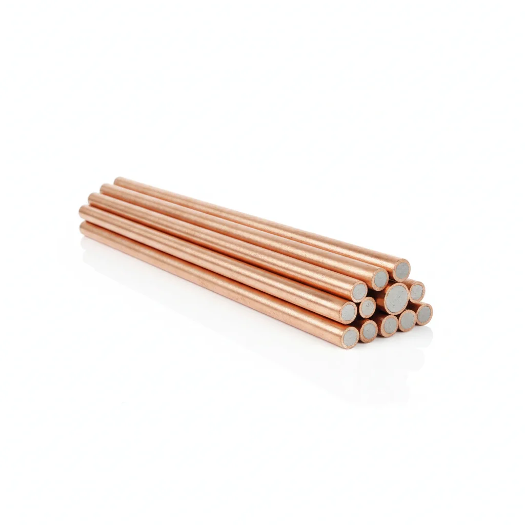
| Copper-Clad Steel Grounding Rod | Exothermic Welding Powder | Grounding Flat Steel | |
|---|---|---|---|
| SPEC | Φ14 ~ Φ20mm×2.5m | 90g/150g/200g | 40×4 ~ 50×5mm |
| MATERIAL | Steel core + copper layer ≥0.25mm | Copper oxide + aluminum powder | Q235B hot-dip galvanized |
| GRADE | — | — | — |
| FINISH | HDG >=55um per ISO 1461 | HDG >=55um per ISO 1461 | HDG >=55um per ISO 1461 |
| CORROSION | C3 (ISO 12944-2) | C3 (ISO 12944-2) | C3 (ISO 12944-2) |
| TEMP | -20°C to +80°C | -20°C to +80°C | -20°C to +80°C |
| WEIGHT | ~0.5 kg/piece | ~0.5 kg/piece | ~0.5 kg/piece |
| MOQ | 100 pcs | 100 pcs | 100 pcs |
| PACK | VCI paper + carton | VCI paper + carton | VCI paper + carton |
| STD | ISO 898-1, GB/T 3098.1 | ISO 898-1, GB/T 3098.1 | ISO 898-1, GB/T 3098.1 |
| USE | Grounding electrode | Grounding grid connection | Grounding main conductor |
PROCEDURE
- Drive the Φ14–Φ20mm copper-clad steel grounding rod vertically to a depth where the top is at least 0.8m below grade, spacing rods at least 5m apart.
- Clean the connection area on the rod and the 40×4–50×5mm galvanized flat steel with a wire brush to remove all dirt and oxide.
- Place the exothermic welding mold around the joint, ensuring it is dry and free of moisture; pour the 90g/150g/200g powder (copper oxide + aluminum) into the mold.
- Ignite the powder with the flint igniter, allow the molten copper to flow and form the weld, then let it cool naturally before removing the mold.
- Inspect the weld for full fusion and absence of porosity; brush off slag and apply a cold galvanizing coating to the weld area for added corrosion protection.
COMMON ERRORS
| ✕ WRONG | CONSEQUENCE | ✓ CORRECT |
|---|---|---|
| Using a galvanized steel grounding rod in acidic soil (pH<5) | Rapid corrosion of the zinc coating and steel core, leading to premature rod failure and rising grounding resistance within a few years. | Select copper-clad steel rods with copper layer ≥0.25mm for acidic soil conditions. |
| Performing exothermic welding on a damp or rainy day without drying the mold | Moisture in the mold causes porosity and slag inclusion, reducing joint cross-section to 40-70% of design and risking open circuit under fault current. | Ensure mold and surfaces are completely dry; do not weld in rainy conditions; use certified operators and proper powder ratio. |
MAINTENANCE
Test grounding resistance annually before the thunderstorm season (when soil is driest); if resistance exceeds the design target (e.g., 0.5Ω for substations per GB 50065), check for electrode corrosion (replace if copper layer <0.15mm) and exothermic weld integrity (infrared temperature difference >5°C indicates poor contact).
Plan B · Reinforced Type for High Soil Resistivity
C4 Harsh per ISO 12944-2
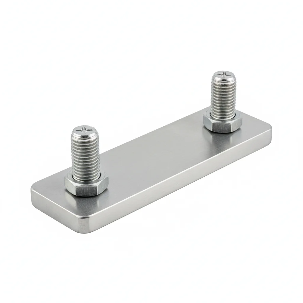
| Copper-Clad Steel Grounding Rod | Exothermic Welding Powder | Grounding Flat Steel | |
|---|---|---|---|
| SPEC | Φ14 ~ Φ20mm×2.5m | 90g/150g/200g | 40×4 ~ 50×5mm |
| MATERIAL | Steel core + copper layer ≥0.25mm | Copper oxide + aluminum powder | Q345B Dacromet |
| GRADE | — | — | — |
| FINISH | HDG >=55um per ISO 1461 | HDG >=55um per ISO 1461 | HDG >=55um per ISO 1461 |
| CORROSION | C3 (ISO 12944-2) | C3 (ISO 12944-2) | C3 (ISO 12944-2) |
| TEMP | -20°C to +80°C | -20°C to +80°C | -20°C to +80°C |
| WEIGHT | ~0.5 kg/piece | ~0.5 kg/piece | ~0.5 kg/piece |
| MOQ | 100 pcs | 100 pcs | 100 pcs |
| PACK | VCI paper + carton | VCI paper + carton | VCI paper + carton |
| STD | ISO 898-1, GB/T 3098.1 | ISO 898-1, GB/T 3098.1 | ISO 898-1, GB/T 3098.1 |
| USE | Grounding electrode | Grounding grid connection | Grounding main conductor |
PROCEDURE
- Clean rod and connector surfaces with a wire brush to remove oxides, then wipe with acetone to remove grease.
- Drive copper-clad steel rods vertically into the high-resistivity soil, maintaining spacing at least twice the rod length.
- Apply exothermic welding powder (90g/150g/200g) to form connections between rods and flat steel; ensure mold is dry and free of moisture.
- After welding, remove slag and inspect joint for full fusion; verify no porosity or inclusions.
- Lay Q345B Dacromet flat steel in trenches, connecting to rods with exothermic welds; cover with soil and compact.
- For deep well grounding, install ion grounding rods with resistance reducing agent, following manufacturer's instructions.
COMMON ERRORS
| ✕ WRONG | CONSEQUENCE | ✓ CORRECT |
|---|---|---|
| Welding in damp or rainy conditions without drying the mold. | Moisture causes porous welds, reducing joint cross-section and increasing resistance, risking open circuit under fault. | Ensure mold and materials are dry; avoid welding in rain or high humidity. |
| Using undersized copper-clad steel rods in high resistivity soil without adding deep wells. | Grounding resistance remains above the IEEE 80 target, leading to unsafe touch and step potentials. | Combine deep well rods (15-30m) and resistance reducing agent to meet resistance targets. |
MAINTENANCE
At each overhaul window, measure grounding resistance with a clamp tester; compare against IEEE 80 target. Inspect exothermic welds for corrosion or cracks; test copper layer thickness on rods—replace if below 0.15mm. Check soil resistivity seasonally; if changes exceed 30%, consider additional electrodes.
Plan C · Reinforced Type for High Soil Resistivity
C5-M Extreme per ISO 12944-2
| Copper-Clad Steel Grounding Rod | Exothermic Welding Powder | Grounding Flat Steel | Inspection and Maintenance Tool Kit | |
|---|---|---|---|---|
| SPEC | Φ14 ~ Φ20mm×2.5m | 90g/150g/200g | 40×4 ~ 50×5mm | Accessory |
| MATERIAL | Steel core + copper layer ≥0.25mm | Copper oxide + aluminum powder | Q235B hot-dip Dacromet + sealing layer | — |
| GRADE | — | — | — | — |
| FINISH | HDG >=55um per ISO 1461 | HDG >=55um per ISO 1461 | HDG >=55um per ISO 1461 | HDG >=55um per ISO 1461 |
| CORROSION | C3 (ISO 12944-2) | C3 (ISO 12944-2) | C3 (ISO 12944-2) | C3 (ISO 12944-2) |
| TEMP | -20°C to +80°C | -20°C to +80°C | -20°C to +80°C | -20°C to +80°C |
| WEIGHT | ~0.5 kg/piece | ~0.5 kg/piece | ~0.5 kg/piece | ~0.5 kg/piece |
| MOQ | 100 pcs | 100 pcs | 100 pcs | 100 pcs |
| PACK | VCI paper + carton | VCI paper + carton | VCI paper + carton | VCI paper + carton |
| STD | ISO 898-1, GB/T 3098.1 | ISO 898-1, GB/T 3098.1 | ISO 898-1, GB/T 3098.1 | ISO 898-1, GB/T 3098.1 |
| USE | Grounding electrode | Grounding grid connection | Grounding main conductor | Periodic torque verification |
PROCEDURE
- Clean surfaces with a solvent to remove all contaminants; verify copper layer thickness on rods meets ≥0.25mm.
- Drive deep well rods (15-30m) into the ground using a drilling rig; backfill with graphite resistance reducing agent.
- Use exothermic welding to connect rods to Q235B flat steel with Dacromet plus sealing layer; ensure molds are dry and powder is correct grade.
- Apply a protective sealant over all connections and exposed metal to prevent corrosion in the aggressive soil.
- Install corrosion monitoring coupons near critical joints to track corrosion rates.
- Document installation details, including soil resistivity and pH measurements, for baseline reference.
COMMON ERRORS
| ✕ WRONG | CONSEQUENCE | ✓ CORRECT |
|---|---|---|
| Selecting galvanized steel instead of copper-clad steel in acidic, high-resistivity soil. | Rapid corrosion of galvanizing leads to increased grounding resistance and premature failure. | Use copper-clad steel rods with copper layer ≥0.254mm per UL 467 and Dacromet-coated flat steel. |
| Skipping the use of resistance reducing agent in rocky or sandy soil. | Grounding resistance remains too high, failing IEEE 80 requirements. | Incorporate graphite or chemical resistance reducing agents around rods to lower soil resistivity. |
MAINTENANCE
Inspect monitoring coupons each season; if corrosion rate exceeds 0.02mm/year, plan for rod replacement. Test grounding resistance annually before thunderstorm season; if out of tolerance, check welds for corrosion and copper layer thickness (replace if <0.15mm). Verify soil resistivity changes; if >30% deviation, add deep wells or replace electrodes.
SELECTION GUIDE
Still unsure which grounding plan fits your site?
| Operating condition | Recommended option | Key basis |
|---|---|---|
| Soil resistivity ≤500Ω·m, neutral soil | Plan A: Copper-clad steel grounding rods (copper layer ≥0.25mm) + exothermic welding + Q235B hot-dip galvanized flat steel 40×4~50×5mm | IEEE 80 |
| Soil resistivity >1000Ω·m (mountainous/Gobi) | Plan B: Deep well grounding rods 15-30m + graphite resistance reducing agent; Q345B Dacromet flat steel | IEEE 80 |
| Acidic soil pH<5 | Increase copper layer thickness to ≥0.5mm or use pure copper grounding rods | ASTM B227 |
| Grounding resistance target | Substation ≤0.5Ω (GB 50065), transmission line ≤10Ω | GB 50065 |
| Exothermic welding joint quality | Matched mold and powder + certified operators; tensile test random ≥2% of joints to ≥70% of base material strength; no welding in rainy conditions; mechanical crimping as alternative | IEEE 837 |
REFERENCED STANDARDS
Technical Basis and Reference Standards
SUPPLIER CAPABILITY
Quality, Delivery & Customization
Quality Control
- ✓MTC material certificates with every batch
- ✓Key parts sampled for hardness/salt spray/torque coefficient
- ✓100% inspection or AQL sampling before shipment
Delivery
- ✓Standard parts made to order: 7-15 days
- ✓Custom parts: 25-45 days
- ✓FOB/CIF/DDP supported
Customization
- ✓Drawing review and material matching
- ✓Non-standard sizes/heads/threads
- ✓Small-batch prototyping supported
Certification
- ✓Material certificates (MTC)
- ✓Spectrographic analysis reports
- ✓Salt spray test reports (on request)
MOQ: No MOQ for standard parts; custom parts assessed by process complexity
FAQ
Frequently Asked Questions
RELATED READING
Keep Reading & Next Step
NEXT: SELECTION & RFQ
Busbar FittingsFollow this page's selection path to the same-scenario RFQ page.
RELATED TOPIC
White Paper on Grounding Resistance Reduction Solutions for Photovoltaic Power StationsBEYOND TECHNICAL SPECS
Finding the right factory, controlling quality, delivering on time — that's the real challenge. We cover fasteners, rubber, plastics, industrial textiles. One team, end to end.
SEE CAPABILITIES →