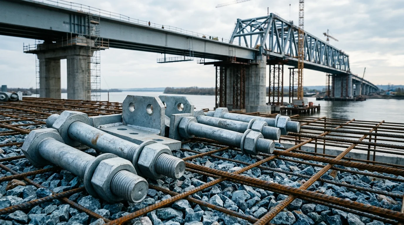
Conveyor System Fastener Selection: Bearing, Gearbox, Tensioner
Select fasteners for conveyor subsystems based on operating conditions. Compare Plan A (roller bearing housing bolts, HDG), Plan B (gearbox flange bolts, Dacromet), and Plan C (tensioner adjustment screws, stainless steel). Each plan addresses specific failure risks: bearing seal failure, flange bolt loosening at high temperature, and stress corrosion cracking
RISK AUDIT // ENGINEERING DIAGNOSIS
Procurement Pitfall Guide
"Roller seizures, gearbox leaks, and tensioner cracks: the three failure modes that stop conveyor lines."
QC-AUDIT // REV.5
SCALE 1:1 · 03 ITEMS
RISK-01
Poor Conveyor Roller Seal Leads to Bearing Water and Dust Ingress
Corrective Measures
RISK-02
Gearbox Flange Bolt Loosening at High Temperature
Corrective Measures
RISK-03
Tensioner Bolt Stress Corrosion Cracking
Corrective Measures
FIELD-SPECIFIC INSIGHT
Conveyor Fastener Selection: Coating vs. Environment
The three plans differ in coating and material to match corrosion severity: Plan A uses hot-dip galvanized (C3 standard), Plan B uses Dacromet (C4 harsh), Plan C uses 304 stainless steel (C5-M extreme). However, coating alone does not guarantee performance; installation torque and maintenance intervals are critical
WHAT TO CHECK
- 1Hot-dip galvanized bolts (Plan A) provide sacrificial protection but may suffer from hydrogen embrittlement if not baked; specify HDG per ISO 1461 and request hydrogen embrittlement relief baking
- 2Use anti-seize compound to achieve consistent preload
- 3For higher temperatures or higher chloride levels, consider 316L or duplex stainless steel
| Check | Why it matters | What to specify |
|---|---|---|
| Coating thickness verification | Insufficient coating leads to early corrosion and fastener failure | Request coating thickness report per ISO 1461 (HDG) or ISO 10683 (Dacromet) |
| Preload control method | Under-torque causes loosening; over-torque causes thread stripping or bolt fracture | Specify torque value and tightening method (torque wrench or angle control) in installation procedure |
| Material certificate for stainless steel | Counterfeit 304 may contain high sulfur or low chromium, reducing corrosion resistance | Require material test certificate per EN 10204 3.1 for all stainless steel fasteners |
| Maintenance schedule compliance | Skipping re-torque inspections leads to progressive loosening and unplanned downtime | — |
All coating thickness values and maintenance intervals are based on the page data. For specific project conditions, consult the relevant ISO or CEMA standards
Evidence level: source-page-only
INDUSTRY TECH REFERENCE
From One Seized Idler to a Whole-Belt Fire
A seized idler is the most common ignition source for conveyor fires, and the belt is not just the thing ignited — it is the main fuel carrier, letting fire spread along kilometers of roadway. Walk the chain to see where housing bolts, seals, and inspection each stand, and why an idler costing a few hundred yuan can destroy a whole belt.
- 1Seal failure (the start): dust and water invade the idler bearing seal and contaminate the grease — worn or aged seals let fines and moisture in
- 2Bearing failure, then the roller seizes: rolling elements wear, clearance grows, the idler turns sluggishly and finally locks solid
- 3Sliding friction heats up: the belt rubs over the dead roller and local temperature climbs toward the rubber ignition point — a seized idler is the most common ignition source in conveyor fires
- 4The belt becomes the fuel: a burned belt snaps and rolls back along the conveyor still on fire — the belt itself is the main fuel, spreading fire along kilometers of roadway (Cape Lambert: grade-M non-flame-resistant belting burned continuously)
- 5A real-world cost: at Port Kembla, Australia, in June 2018, one failed idler bearing sparked a belt fire that 70 firefighters took days to control
- 6Mandated countermeasures: US underground coal mines require temperature-triggered drive sprinklers plus full-line CO sensing (slip/sequence switches §75.1102; CO sensors spaced ≤1000 ft, calibrated ≤31 days, function-tested ≤7 days)
No order-of-magnitude estimates are used in this slot.
INDUSTRY TECH REFERENCE
The Take-Up Zone: Reserved Travel, Slippage Detection, and Mandated Parts
Take-up failure starts the slip-to-fire chain: an undersized or stuck counterweight, or a loose screw-type take-up, immediately robs the belt of traction against the drive pulley. These five lines carry numbers you can put straight on the RFQ and into acceptance criteria.
- Reserved travel: fabric-carcass belts reserve take-up travel at 1.5% elongation, steel-cord belts at 0.2% — a 1000 m fabric-carcass conveyor needs 15 m of take-up travel
- The root chain: an undersized or stuck counterweight, or a loose screw take-up, cuts traction → the belt slips → friction heat builds
- Mandated parts: slip and sequence switches are mandatory underground (30 CFR Part 75 Subpart L §75.1102) — slippage is not "to be fixed", it is "must be detected"
- Field check: verify the counterweight's free travel covers belt length × elongation; travel running out is a replace-the-belt signal, not a crank-the-screw signal
- Acceptance lines: state belt length, elongation, converted travel, and screw size on the RFQ, and accept delivery against a verifiable number — do not leave take-up travel to "close enough"
No order-of-magnitude estimates are used in this slot.
INDUSTRY TECH REFERENCE
A Quick Failure Diagnosis for Conveyor Components: Symptom, Root Cause, Fastener Fix
Conveyor-component failures are rarely a bolt "breaking on its own" — seals, take-up, and idler state fail first. The table condenses the four most common chains from the verified failure spectrum: symptom, root cause, the fastener-side fix, and the acceptance anchor, so inspection and procurement can match against them directly.
| Symptom | Root cause (failure mode) | Fastener-side fix | Acceptance anchor |
|---|---|---|---|
| Idler locked, belt back cover wearing abnormally | FM-1 bearing seal failure → water/dust ingress → seizure | Retighten housing bolts and upgrade the seal; replace any seized idler | Listen-and-temperature inspection; underground: slip switch + CO sensing mandated (§75.1102/1103) |
| Belt running off, edges grinding the structure | FM-3 loose idler frame / training-idler fixings or off-center loading | First correct the idlers and retighten the frame bolts — not replace the belt | Watch run-off converge after correction; if edge wear persists, check take-up and loading |
| Belt slipping, slip switch tripping | FM-4 undersized/stuck counterweight or loose screw take-up | Reserve take-up travel at belt length × elongation (fabric 1.5%, steel cord 0.2%) and retighten | Counterweight free travel verifiable; slip switch mandatorily interlocked underground |
| Cover worn thin, carcass exposed | FM-6 seized/dirty idlers, over-tightened cleaners, skirt spillage trapped | Adjust cleaner scraper fixing bolts to the pressure line | Check cleaner pressure and skirt gap together with idler state |
No order-of-magnitude estimates are used in this slot.
INDUSTRY TECH REFERENCE
Drive and Incline Zones: Bearing-Housing Bolts, Flange Bolts, and Backstops
The drive zone is the hottest and most consequential part of a conveyor: a slipping belt can heat the pulley surface to 500°C, underground drives are mandated to carry temperature-triggered sprinklers, and inclined conveyors must have backstops. Every figure and requirement below is traceable — match your RFQ and acceptance against it.
| Location | Fastener | Key parameters | Compliance & acceptance |
|---|---|---|---|
| Drive / bend pulley bearing housings | Bearing-housing bolts | Pulley surface can reach 500°C during slip (drum-friction test ceiling) | Temperature-triggered sprinklers protect the drive and 50 ft of flame-resistant belt downstream (MSHA §75.1101) |
| Drive unit (gearbox flanges) | Flange bolts | Slip friction heat is one link in the seize→fire chain; flanges sit in the drive-zone heat field | Underground main and secondary belt drives must carry temperature-triggered sprinklers with slip/sequence switches interlocked (§75.1101/1102) |
| Inclined-section drive units | Backstop connection bolts | Loaded inclined conveyors can run back on stop | Backstop/brake mandated (30 CFR §56.14113 for surface inclined conveyors at metal/nonmetal mines) |
No order-of-magnitude estimates are used in this slot.
INDUSTRY TECH REFERENCE
On This Conveyor-Component Order: Fasteners In, Equipment Bodies Out
Draw the boundary before RFQing conveyor-component fasteners. In scope: belt-clip bolt/rivet sets, idler frame bolts, bearing retaining rings, take-up screws, pulley bearing-housing bolts, cleaner scraper fixing bolts, and backstop connection bolts. Out of scope: the belt itself (rubber plus carcass layers), idler shells and bearings, motorized pulleys, and vulcanized-splice installation. Bearing rolling elements and seals inside an idler belong to the bearing assembly, not a fastener RFQ; accept retaining rings against the current GB/T 894/893-2017 — the old 1986 editions are obsolete, so do not take delivery against a withdrawn standard.
No order-of-magnitude estimates are used in this slot.
PLAN COMPARISON
Three-Plan Core Parameter Comparison
Compare row by row. Click column headers to jump to plan details.
| A · Plan A · Roller Bearing Housing Bolts | B · Plan B · Gearbox Flange Bolts and Coupling Pins | C · Plan C · Tensioner Adjustment Bolts and Rail Clamps | |
|---|---|---|---|
| 1. M12×80 HEX BOLT | |||
| SPEC | Grade 8.8, Hot-Dip Galvanized | Grade 10.9, Dacromet | 304 Stainless Steel |
| MATERIAL | — | — | 304 Stainless Steel |
| GRADE | Grade 8.8 | Grade 10.9 | — |
| FINISH | HDG >=55um per ISO 1461 | HDG >=55um per ISO 1461 | HDG >=55um per ISO 1461 |
| 2. BEARING HOUSING U-BOLT | |||
| SPEC | Q235B, Φ16 | 45# Steel Quenched and Tempered | AL6063 Anodized |
| MATERIAL | Q235B | 45# Steel | — |
| FINISH | HDG >=55um per ISO 1461 | HDG >=55um per ISO 1461 | HDG >=55um per ISO 1461 |
| 3. ANTI-LOOSENING SPRING WASHER | |||
| SPEC | GB/T 93, Galvanized | Oil-Resistant Rubber | M10, PA66 |
| MATERIAL | — | EPDM Rubber | PA66 |
| FINISH | HDG >=55um per ISO 1461 | HDG >=55um per ISO 1461 | HDG >=55um per ISO 1461 |
SELECTION GUIDE
How to Choose Fasteners Based on Conveyor Operating Conditions?
| Operating condition | Recommended option | Key basis |
|---|---|---|
| Low speed, heavy load, dusty environment; poor roller seal allows water and dust into the bearing (dust concentration >50mg/m³), bearing seizes within 3-7 days, belt slides on the stationary roller | Plan A — roller bearing housing bolts: M12×80 hex bolt (grade 8.8, hot-dip galvanized) + Q235B Φ16 bearing housing U-bolt + GB/T 93 anti-loosening spring washer; IP65 or higher sealed bearings and quarterly roller rotation check | C3 per ISO 12944-2; ISO 1461 hot-dip galvanizing; GB/T 93 spring washer |
| Medium speed continuous operation, torque transmission; gearbox flange at 120°C and 0.8MPa, ordinary bolt preload decays 30%, leakage raises maintenance frequency 3 times and shortens equipment life to 2 years | Plan B — gearbox flange bolts: M16×100 high strength bolt (grade 10.9, Dacromet, recommended preload about 85kN, final tightening torque about 220 N·m) + EPDM flange sealing gasket; preload control process keeps retention ≥95% at 120°C, seal life over 5 years | C4 per ISO 12944-2; ISO 10683 Dacromet; GB/T 3098.1 |
| High speed precision, frequent adjustment; humid environment with 200ppm chloride ions and 50°C, 304 stainless bolts develop stress corrosion cracks within 6 months and tension drops 50% | Plan C — tensioner adjustment bolts: M10 304 stainless trapezoidal lead screw + AL6063 anodized rail clamp block + M10 PA66 anti-loosening nylon nut; upgrade to duplex stainless steel (e.g., 2205) or titanium alloy and use torque + angle method, life over 24 months | C5-M per ISO 12944-2; EN 10204 3.1 material test certificate |
| Higher temperatures or higher chloride levels; procurement-time coating and material verification | Use anti-seize compound for consistent preload; consider 316L or duplex stainless steel; request coating thickness report per ISO 1461 (HDG) or ISO 10683 (Dacromet) and material test certificate per EN 10204 3.1 for all stainless steel fasteners | ISO 1461; ISO 10683; EN 10204 3.1 |
Plan A · Roller Bearing Housing Bolts
C3 (ISO 12944-2)
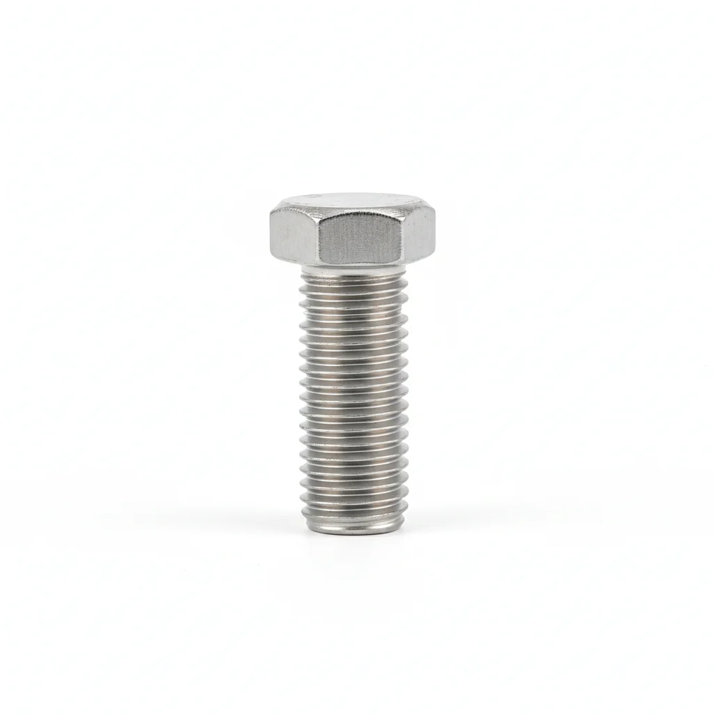
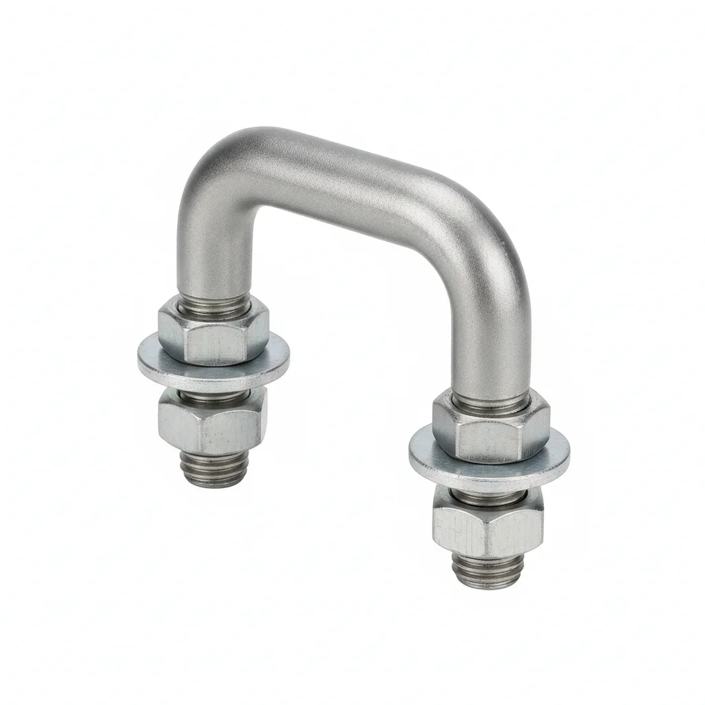
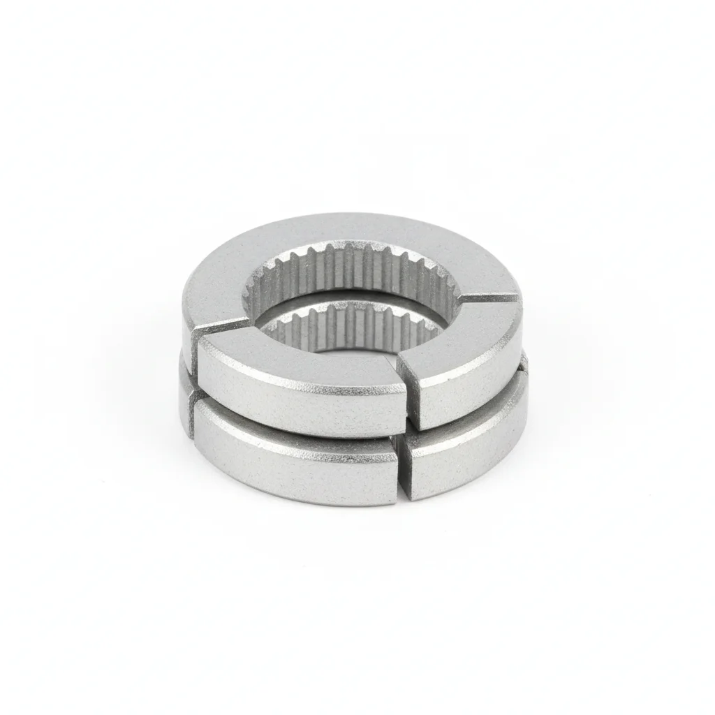
| M12×80 Hex Bolt | Bearing Housing U-Bolt | Anti-Loosening Spring Washer | |
|---|---|---|---|
| SPEC | Grade 8.8, Hot-Dip Galvanized | Q235B, Φ16 | GB/T 93, Galvanized |
| MATERIAL | — | Q235B | — |
| GRADE | Grade 8.8 | — | — |
| FINISH | HDG >=55um per ISO 1461 | HDG >=55um per ISO 1461 | HDG >=55um per ISO 1461 |
| CORROSION | C3 (ISO 12944-2) | C3 (ISO 12944-2) | C3 (ISO 12944-2) |
| TEMP | -20°C to +80°C | -20°C to +80°C | -20°C to +80°C |
| WEIGHT | ~0.5 kg/piece | ~0.5 kg/piece | ~0.5 kg/piece |
| MOQ | 100 pcs | 100 pcs | 100 pcs |
| PACK | VCI paper + carton | VCI paper + carton | VCI paper + carton |
| STD | ISO 898-1, GB/T 3098.1 | ISO 898-1, GB/T 3098.1 | ISO 898-1, GB/T 3098.1 |
| USE | Hot-Dip Galvanized | Φ16 | Galvanized |
PROCEDURE
- Clean the bearing housing seat and bolt holes with isopropyl alcohol to remove grease and dust, ensuring a dry surface before assembly.
- Place the M12×80 hex bolt through the housing flange, add the anti-loosening spring washer under the nut, and hand-tighten to seat the components.
- Tighten in a star pattern with a calibrated torque wrench to the specified torque for Grade 8.8 M12 fasteners, then mark with torque seal paint.
- Verify bolt protrusion is uniform and the housing is seated without gaps; check a 5% sample with a feeler gauge for flushness.
- Apply a light coat of anti-seize on threads if re-tightening is expected during maintenance, and record torque values in the QA log.
COMMON ERRORS
| ✕ WRONG | CONSEQUENCE | ✓ CORRECT |
|---|---|---|
| Using a non-galvanized bolt or one with damaged HDG coating | Corrosion initiates at the damaged areas, compromising the C3 rating and leading to early seizure of the bearing housing bolts in dusty, humid conveyor environments. | Inspect the HDG coating (≥55µm per ISO 1461) before installation; replace any bolts with scratches or bare spots. |
| Tightening bolts in a circular sequence instead of a star pattern | Uneven clamp load distorts the bearing housing, causing misalignment and premature bearing seal failure. | Always tighten in a star or cross pattern to ensure uniform preload across the housing flange. |
MAINTENANCE
Inspect bolts for loosening and corrosion at each overhaul window or whenever belt tracking is adjusted; re-torque any fastener showing relaxation and replace any with corrosion affecting more than 5% of surface area or pitting depth exceeding 0.3mm.
Plan B · Gearbox Flange Bolts and Coupling Pins
C4 Harsh per ISO 12944-2
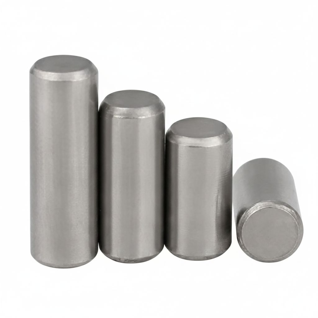
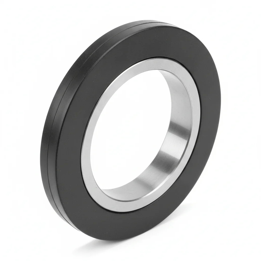
| M16×100 High Strength Bolt | Elastic Coupling Pin | Flange Sealing Gasket | |
|---|---|---|---|
| SPEC | Grade 10.9, Dacromet | 45# Steel Quenched and Tempered | Oil-Resistant Rubber |
| MATERIAL | — | 45# Steel | EPDM Rubber |
| GRADE | Grade 10.9 | — | — |
| FINISH | HDG >=55um per ISO 1461 | HDG >=55um per ISO 1461 | HDG >=55um per ISO 1461 |
| CORROSION | C3 (ISO 12944-2) | C3 (ISO 12944-2) | Not applicable (polymer) |
| TEMP | -20°C to +80°C | -20°C to +80°C | -20°C to +80°C |
| WEIGHT | ~0.5 kg/piece | ~0.5 kg/piece | ~0.5 kg/piece |
| MOQ | 100 pcs | 100 pcs | 100 pcs |
| PACK | VCI paper + carton | VCI paper + carton | VCI paper + carton |
| STD | ISO 898-1, GB/T 3098.1 | ISO 898-1, GB/T 3098.1 | ISO 898-1, GB/T 3098.1 |
| USE | Dacromet | Elastic Coupling Pin | Flange Sealing Gasket |
PROCEDURE
- Degrease gearbox flange faces with acetone to remove oil and grease, ensuring surface roughness Ra < 3.2 μm for proper gasket seating.
- Position the oil-resistant EPDM gasket between flanges; insert M16 Dacromet-coated bolts through clean holes.
- Tighten bolts in a cross-pattern sequence to achieve uniform clamp load, using a calibrated torque wrench.
- After initial tightening, perform a second pass to the final torque value to compensate for relaxation; verify with a torque auditor.
- Mark each bolt head and nut with a paint stripe after final torque to indicate proper seating during subsequent inspections.
COMMON ERRORS
| ✕ WRONG | CONSEQUENCE | ✓ CORRECT |
|---|---|---|
| Using a lower-grade bolt (e.g., 8.8) instead of Grade 10.9 for the gearbox flange | The bolt cannot sustain the required preload; under 120°C operation, preload decays faster, leading to flange separation and oil leakage. | Verify the bolt grade is 10.9 per ISO 898-1 before installation; use Dacromet-coated bolts to resist corrosion. |
| Overtightening the elastic coupling pin beyond its elastic range | The pin yields or fractures, causing coupling misalignment and increased vibration that damages the gearbox bearings. | Follow the manufacturer's torque specification for the 45# steel quenched and tempered pin; use a torque wrench and never exceed the specified value. |
| Installing the flange gasket without cleaning the sealing surfaces | Residual oil or debris prevents proper gasket compression, resulting in leaks at the flange joint under pressure. | Clean both flange faces with acetone and inspect for nicks or burrs; install a new EPDM gasket each time the joint is opened. |
MAINTENANCE
Inspect gearbox flange bolts for loosening at each overhaul window or whenever gearbox temperature exceeds 120°C; re-torque any bolt that has lost more than 80% of its specified preload. Replace Dacromet-coated bolts showing corrosion affecting more than 5% of surface area or pitting deeper than 0.3 mm. Check coupling pins for wear or deformation during scheduled maintenance; replace if the pin shows signs of yielding. Maintain a CMMS log of torque audits and corrosion findings.
Plan C · Tensioner Adjustment Bolts and Rail Clamps
C5-M Extreme per ISO 12944-2
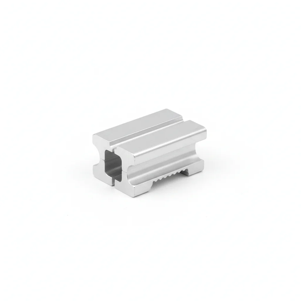
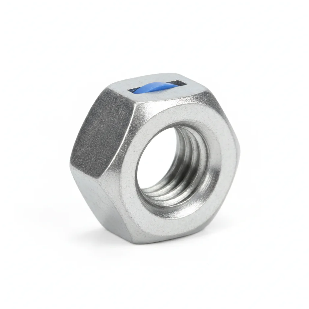
| M10 Trapezoidal Lead Screw | Rail Clamp Block | Anti-Loosening Nylon Nut | |
|---|---|---|---|
| SPEC | 304 Stainless Steel | AL6063 Anodized | M10, PA66 |
| MATERIAL | 304 Stainless Steel | — | PA66 |
| GRADE | — | — | — |
| FINISH | HDG >=55um per ISO 1461 | HDG >=55um per ISO 1461 | HDG >=55um per ISO 1461 |
| CORROSION | C3 (ISO 12944-2) | C3 (ISO 12944-2) | C3 (ISO 12944-2) |
| TEMP | -20°C to +80°C | -20°C to +80°C | -20°C to +80°C |
| WEIGHT | ~0.5 kg/piece | ~0.5 kg/piece | ~0.5 kg/piece |
| MOQ | 100 pcs | 100 pcs | 100 pcs |
| PACK | VCI paper + carton | VCI paper + carton | VCI paper + carton |
| STD | ISO 898-1, GB/T 3098.1 | ISO 898-1, GB/T 3098.1 | ISO 898-1, GB/T 3098.1 |
| USE | M10 Trapezoidal Lead Screw | Rail Clamp Block | PA66 |
PROCEDURE
- Clean the tensioner threads and rail clamp surfaces with MEK solvent to remove all contaminants; verify surface roughness Ra < 1.6 μm for precise adjustment.
- Apply a marine-grade anti-seize compound to the M10 trapezoidal lead screw threads to ensure smooth adjustment and prevent galling.
- Assemble the rail clamp block with the 304 stainless steel lead screw and secure with the PA66 anti-loosening nylon nut.
- Adjust the tensioner to the required belt tension using a torque wrench; the nylon insert in the nut provides vibration resistance during high-speed operation.
- After final adjustment, mark the reference position on the lead screw and clamp block to allow quick verification of tension loss during operation.
COMMON ERRORS
| ✕ WRONG | CONSEQUENCE | ✓ CORRECT |
|---|---|---|
| Using a standard hex nut instead of the PA66 nylon-insert nut | Under high-speed vibration, the nut loosens, causing the tensioner to lose adjustment and the belt to misalign, leading to product jams. | Always use the anti-loosening nylon nut specified; replace the nut if the nylon insert is worn or damaged. |
| Overtightening the 304 stainless steel lead screw beyond its elastic limit | The screw may strip or fracture, or the thread surface may gall, preventing further adjustment and causing downtime. | Use a torque wrench to apply the specified torque; for 304 stainless steel, avoid high torque and use anti-seize compound to reduce friction. |
| Adjusting the tensioner without checking rail parallelism | Misalignment causes uneven belt wear and increases stress on the lead screw, potentially leading to stress corrosion cracking in humid chloride environments. | Use a laser alignment tool or dial indicator to verify parallelism within ±0.1 mm before finalizing the tensioner adjustment. |
MAINTENANCE
Inspect tensioner bolts and rail clamps at each scheduled maintenance shutdown or when belt misalignment is observed. Verify the nylon nut still provides locking resistance; replace if the insert is cracked or loose. Check the 304 stainless steel lead screw for any signs of stress corrosion cracking, especially in humid or chloride-rich environments; replace any cracked components immediately. Re-apply anti-seize compound during reassembly. Record all adjustments and inspections in the CMMS.
REFERENCED STANDARDS
Technical Basis and Reference Standards
Belt Conveyors
Conveyor BeltContinuous handling equipment - Belt conveyors
Conveyor Equipment Manufacturers Association StandardFlexible couplings for shaft connections
Belt Conveyor DesignMechanical properties of fasteners - Bolts, screws and studs
Belt ConveyorsShaft-mounted bearing housings
SUPPLIER CAPABILITY
Quality, Delivery & Customization
Quality Control
- ✓MTC material certificates with every batch
- ✓Key parts sampled for hardness/salt spray/torque coefficient
- ✓100% inspection or AQL sampling before shipment
Delivery
- ✓Standard parts made to order: 7-15 days
- ✓Custom parts: 25-45 days
- ✓FOB/CIF/DDP supported
Customization
- ✓Drawing review and material matching
- ✓Non-standard sizes/heads/threads
- ✓Small-batch prototyping supported
Certification
- ✓Material certificates (MTC)
- ✓Spectrographic analysis reports
- ✓Salt spray test reports (on request)
MOQ: No MOQ for standard parts; custom parts assessed by process complexity
FAQ
Frequently Asked Questions
RELATED READING
Keep Reading & Next Step
BEYOND TECHNICAL SPECS
Finding the right factory, controlling quality, delivering on time — that's the real challenge. We cover fasteners, rubber, plastics, industrial textiles. One team, end to end.
SEE CAPABILITIES →