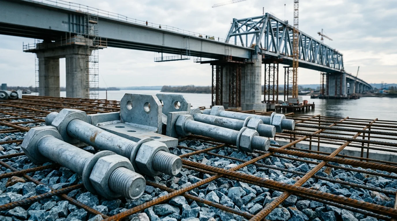
Heavy Equipment Fasteners: Hydraulic Pin Shafts, Gearbox Bolts, Track Plate Bolts
Select the right fastener for excavator hydraulic cylinders, gearbox housings, and track plates. Compare surface hardening vs. Dacromet vs. Phosphating, and understand how eccentric loads, corrosive environments, and impact loads affect fastener life. Includes inspection intervals and torque recheck requirements
RISK AUDIT // ENGINEERING DIAGNOSIS
Procurement Pitfall Guide
"When excavator buckets bite into rock, the pin shaft takes the hit—here's what fails first."
QC-AUDIT // REV.5
SCALE 1:1 · 03 ITEMS
RISK-01
Local peeling of chrome plating on hydraulic cylinder piston rod under eccentric load
Corrective Measures
RISK-02
Corrosive environment causes sharp drop in fatigue life
Corrective Measures
RISK-03
Heavy impact load causes thread stripping or bolt fracture
Corrective Measures
FIELD-SPECIFIC INSIGHT
How to Choose Fasteners for Heavy Equipment: Key Differences Between Hydraulic, Gearbox, and Track Applications
Heavy equipment fasteners face different failure modes depending on the subsystem. Hydraulic cylinder pin shafts suffer from chrome plating peeling under eccentric loads; gearbox bolts risk thread stripping under high preload; track plate bolts experience impact loads causing loosening. The table below summarizes the critical selection criteria
WHAT TO CHECK
- 1Hydraulic cylinder pin shafts: surface hardened HRC50-55 resists wear from reciprocating motion; O-ring seal FKM prevents oil leakage
- 2Gearbox housing bolts: Grade 12.9 with Dacromet coating provides corrosion resistance in C4 harsh environments; Nordlock washers prevent loosening under vibration
- 3Track plate bolts: Grade 12.9 with phosphated anti-galling coating reduces friction during installation; anti-loosening wire secures against impact loads
- 4Inspection every 250 operating hours: re-torque any fastener below 80% specified torque; replace if corrosion affects >5% surface area or pitting depth exceeds acceptable limits
| Check | Why it matters | What to specify |
|---|---|---|
| Application | Determines load type (eccentric, high preload, impact) and failure mode | Hydraulic cylinder, gearbox, or track system in your RFQ |
| Coating/Finish | Corrosion resistance and galling prevention affect service life | Surface hardened HRC50-55, Dacromet, or phosphated anti-galling per ISO 12944-2 |
| Grade | Strength class determines load capacity and preload retention | Grade 12.9 for bolts; specify yield strength and hardness for pin shafts |
| Anti-loosening feature | Prevents fastener failure under vibration or impact | Nordlock washer or anti-loosening wire for gearbox and track bolts |
All fasteners must meet ISO 898-1 mechanical properties. Inspection intervals and replacement criteria are based on standard maintenance practices; adjust per OEM recommendations
Evidence level: source-page-only
INDUSTRY TECH REFERENCE
How Track-Shoe Bolts Go from Improper Tightening to a Thrown Track
The running gear is the most frequent loosening source on a track machine — the OEM names improper tightening the number-one cause outright. Walk this chain once and you will see why the recheck window is the interception point.
- 1Improper tightening is the number-one cause: the OEM guide states plainly that the leading cause of shoe loosening is improperly tightened shoe hardware — torque short of the mark or the wrong sequence, and the shoe never truly seats against the link from the start
- 2Loosening in service: digging and travel shocks plus cornering side loads cycle through the joint, the residual preload keeps dropping, and the shoe begins to shift on the track link
- 3Misalignment feeds wear: the shifted shoe puts abnormal wear onto the track pins, and the pin-to-link seating degrades
- 4Slack and derailment: the whole chain goes slack, and under an extreme load a track pin lets go — a broken or thrown track
- 5The record: a Cat 235D threw its track while dredging a pond and was down on the spot (front-line community record, two confirmations)
- 6The interception: tighten per the OEM torque-plus-angle method (run to the specified initial torque, then add 1/3 turn); inspect and re-tighten as needed 50-100 operating hours after new fitment or refit — stop the looseness before the misalignment
No order-of-magnitude estimates are used in this slot.
INDUSTRY TECH REFERENCE
Know the Load Spectrum First: Shock, Tilting, or Rolling
Fastener selection on heavy equipment starts from the duty spectrum, not the spec sheet: the attachment, the swing joint, and the running gear carry entirely different load shapes and therefore different failure modes — match the spectrum first, then talk selection and acceptance.
The "20-tonne-class ≈ 20 t" is a magnitude approximation.
INDUSTRY TECH REFERENCE
Carrier End Covers and Drive Sprocket: Torque Bands by Machine Series
Torque is not "tighten-it-firmly": among undercarriage retaining parts alone, end-cover bolts jump three torque bands from small to large bulldozers, while sprocket bolts are given as a range in inch sizes. Lock the band before quoting or accepting.
| Fixing point | Machine band | Size and torque | Method and failure |
|---|---|---|---|
| End-cover retaining bolts (carrier/idler) | D5N class (mid-size dozer) | M16, 270±40 N·m | Pre-tighten both bolts evenly before final torque; under-clamping → retaining bolt breaks → carrier/bogie bore damage |
| End-cover retaining bolts (carrier/idler) | D6R class | M20, 540±70 N·m | As above; end-cover sizes float between M16 and M20 by tonnage |
| End-cover retaining bolts (carrier/idler) | D8/D9 class | 7/8″, 750±90 N·m | As above |
| Split drive-sprocket bolts | All series (by model) | 5/8″-1-1/8″, initial torque range 175-870 N·m | Run all nuts to the initial torque, then add 1/3 turn each; improper installation is the main cause of sprocket loosening and damage to connected parts; the split-segment replacement value rests on bolt reliability |
No order-of-magnitude estimates are used in this slot. Torques are the guide's nominal values — follow the machine-specific drawing on site.
INDUSTRY TECH REFERENCE
A Thrown Track: an Excavator Saves Itself, a Dozer Waits for a Crane
Running-gear fastener choice should look at how a machine is recovered after it stops: for the same thrown pin and broken track, the two machine types differ by an order of magnitude in field recovery.
After a track pin lets go and the track breaks, the front-line fix is to align, drive in a new pin, and tack-weld it in place — about 45 minutes to restore the track on site. But for the same thrown track, an excavator can prop itself up with its own bucket and push out of the mud, while a bulldozer has no such self-rescue and is far harder to handle. The difference goes straight into the buying logic: the reliability of running-gear fasteners and pins decides whether a failure is a roughly 45-minute field reset or a crane-call, overhaul-class stoppage. Tightening to the OEM torque-plus-angle method and re-tightening on the OEM rhythm are exactly what keeps failures on the field-fixable side.
The "about 45 minutes" is the duration of a single field-reset case, not a general value. No order-of-magnitude estimates are used in this slot.
PLAN COMPARISON
Three-Plan Core Parameter Comparison
Compare row by row. Click column headers to jump to plan details.
| A · Plan A · Hydraulic Cylinder Ear Pin Shaft and Seal Gland | B · Plan B · Gearbox Housing Bolt and Bearing End Cover | C · Plan C · Track Plate Bolt and Drive Wheel Fastener | |
|---|---|---|---|
| 1. PIN SHAFT | |||
| SPEC | Φ50×200, surface hardened HRC50-55 | Grade 12.9, Dacromet coating | Grade 12.9, phosphated anti-galling |
| GRADE | — | Grade 12.9 | Grade 12.9 |
| FINISH | hot-dip galvanized >=55 μm per ISO 1461 | HDG >=55um per ISO 1461 | HDG >=55um per ISO 1461 |
| 2. O-RING SEAL | |||
| SPEC | FKM, oil and temperature resistant | M16×50, Grade 10.9 | M20×70, Grade 10.9 |
| MATERIAL | EPDM Rubber | — | — |
| GRADE | — | Grade 10.9 | Grade 10.9 |
| FINISH | HDG >=55um per ISO 1461 | HDG >=55um per ISO 1461 | HDG >=55um per ISO 1461 |
| 3. END COVER BOLT | |||
| SPEC | M16×60, Grade 12.9 | NL24, double-stacked self-locking | Φ1.6, galvanized steel wire |
| GRADE | Grade 12.9 | — | — |
| FINISH | HDG >=55um per ISO 1461 | HDG >=55um per ISO 1461 | HDG >=55um per ISO 1461 |
SELECTION GUIDE
How to choose fasteners based on equipment type?
| Operating condition | Recommended option | Key basis |
|---|---|---|
| Hydraulic system, reciprocating motion components (excavator/crane/loader; C3 per ISO 12944-2) | Plan A · Hydraulic Cylinder Ear Pin Shaft and Seal Gland: pin shaft Φ50×200 surface hardened HRC50-55; O-ring seal FKM; end cover bolt M16×60 Grade 12.9 | ISO 898-1 (mechanical properties of fasteners); SAE J1453:2019 (O-ring face seal fittings); FKM seal withstands oil and temperature; surface hardening HRC50-55 resists wear from reciprocating motion |
| Transmission system, high-speed rotating components (rolling mill/crusher/ball mill; C4 harsh per ISO 12944-2) | Plan B · Gearbox Housing Bolt and Bearing End Cover: M24×120 Grade 12.9 with Dacromet coating; bearing end cover bolt M16×50 Grade 10.9; Nordlock NL24 double-stacked self-locking washer | ISO 898-1 (mechanical properties); Dacromet coating for C4 harsh environments; Nordlock double-stacked washers prevent loosening under vibration; periodic torque recheck to design value |
| Travel system, impact load conditions (bulldozer/paver/rotary drilling rig; C5-M extreme per ISO 12944-2) | Plan C · Track Plate Bolt and Drive Wheel Fastener: M22×80 Grade 12.9 phosphated anti-galling; drive wheel ring gear bolt M20×70 Grade 10.9; anti-loosening wire Φ1.6 galvanized steel | ISO 898-1 (mechanical properties); phosphated anti-galling reduces friction during installation; anti-loosening wire secures against impact loads; Grade 12.9 withstands impact loads up to 300kN |
Plan A · Hydraulic Cylinder Ear Pin Shaft and Seal Gland
C3 (ISO 12944-2)
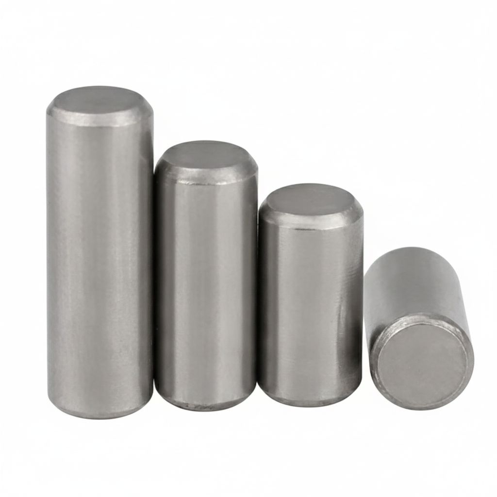
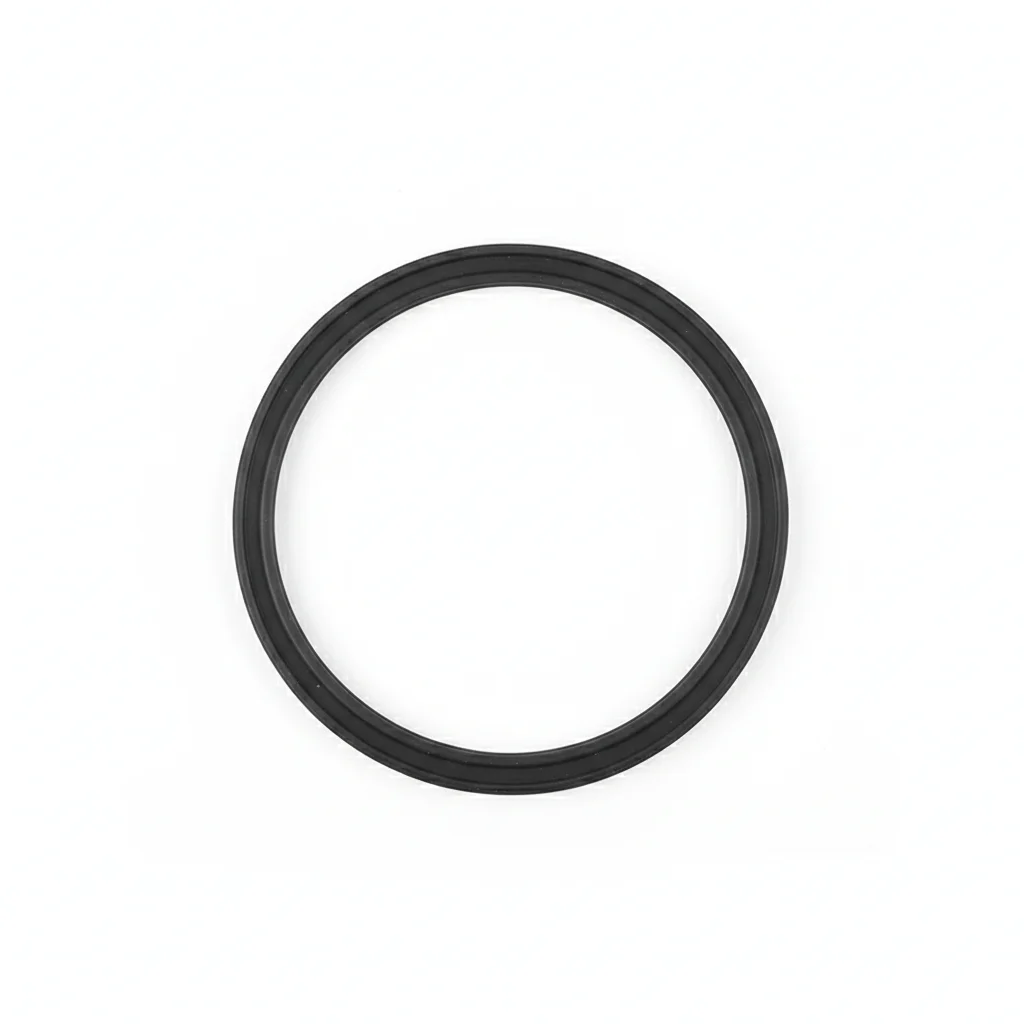
| Pin Shaft | O-Ring Seal | End Cover Bolt | |
|---|---|---|---|
| SPEC | Φ50×200, surface hardened HRC50-55 | FKM, oil and temperature resistant | M16×60, Grade 12.9 |
| MATERIAL | — | EPDM Rubber | — |
| GRADE | — | — | Grade 12.9 |
| FINISH | hot-dip galvanized >=55 μm per ISO 1461 | HDG >=55um per ISO 1461 | HDG >=55um per ISO 1461 |
| CORROSION | C3 (ISO 12944-2) | Not applicable (polymer) | C3 (ISO 12944-2) |
| TEMP | -20°C to +80°C | -20°C to +80°C | -20°C to +80°C |
| WEIGHT | ~0.5 kg/piece | ~0.5 kg/piece | ~0.5 kg/piece |
| MOQ | 100 pcs | 100 pcs | 100 pcs |
| PACK | VCI paper + carton | VCI paper + carton | VCI paper + carton |
| STD | ISO 898-1, GB/T 3098.1 | ISO 898-1, GB/T 3098.1 | ISO 898-1, GB/T 3098.1 |
| USE | Surface hardened HRC50-55 | Oil and temperature resistant | Grade 12.9 |
PROCEDURE
- Degrease the pin shaft bore and gland seat with a solvent; confirm the mating surfaces are free of burrs and within the flatness tolerance for the Φ50×200 shaft.
- Place the FKM O-ring seal in its groove, ensuring no twisting, then slide the pin shaft through the ear and align the end cover holes with the M16×60 Grade 12.9 bolts.
- Tighten the end cover bolts in a crisscross pattern to the torque specified for Grade 12.9, using a calibrated wrench, and mark each bolt after torquing.
- Rotate the cylinder through its full stroke to verify the pin rotates freely without binding; check for any seal leakage around the gland.
- Record the torque values and the batch numbers of the pin shaft, O-ring, and bolts in the assembly log for traceability.
COMMON ERRORS
| ✕ WRONG | CONSEQUENCE | ✓ CORRECT |
|---|---|---|
| Using an unhardened pin shaft instead of the surface-hardened HRC50-55 version | The softer surface wears rapidly under alternating loads, increasing clearance and leading to premature joint failure and oil leakage. | Confirm the pin shaft has been surface hardened to HRC50-55 per the spec before installation; reject any parts lacking the hardness mark. |
| Installing the O-ring seal dry or with the wrong lubricant | The FKM seal can be pinched or torn during assembly, causing hydraulic oil leakage and loss of cylinder pressure. | Lubricate the O-ring with a compatible hydraulic oil or assembly grease, and verify it sits evenly in the groove before mating parts. |
MAINTENANCE
Inspect the pin shaft and seal area at each scheduled service window; measure the pin diameter for wear and replace if the groove depth exceeds 0.3mm. Re-torque the end cover bolts to the specified value if any loosening is detected, and replace the O-ring at each overhaul.
Plan B · Gearbox Housing Bolt and Bearing End Cover
C4 Harsh per ISO 12944-2
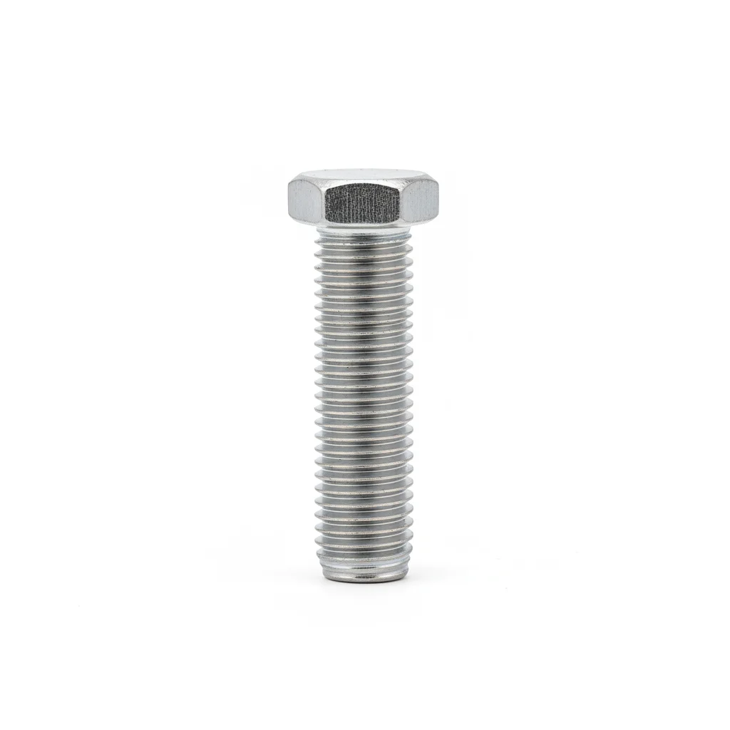
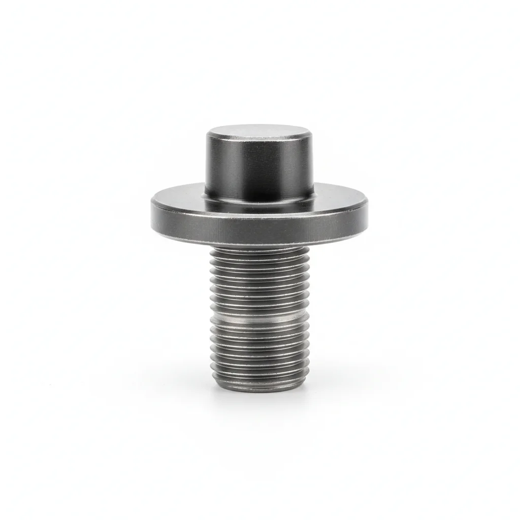
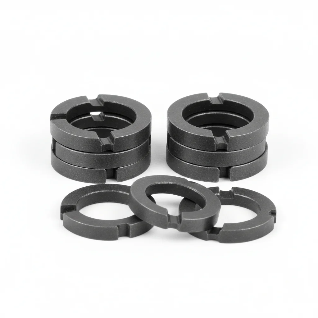
| M24×120 High Strength Bolt | Bearing End Cover Bolt | Nordlock Anti-Loosening Washer | |
|---|---|---|---|
| SPEC | Grade 12.9, Dacromet coating | M16×50, Grade 10.9 | NL24, double-stacked self-locking |
| MATERIAL | — | — | — |
| GRADE | Grade 12.9 | Grade 10.9 | — |
| FINISH | HDG >=55um per ISO 1461 | HDG >=55um per ISO 1461 | HDG >=55um per ISO 1461 |
| CORROSION | C3 (ISO 12944-2) | C3 (ISO 12944-2) | C3 (ISO 12944-2) |
| TEMP | -20°C to +80°C | -20°C to +80°C | -20°C to +80°C |
| WEIGHT | ~0.5 kg/piece | ~0.5 kg/piece | ~0.5 kg/piece |
| MOQ | 100 pcs | 100 pcs | 100 pcs |
| PACK | VCI paper + carton | VCI paper + carton | VCI paper + carton |
| STD | ISO 898-1, GB/T 3098.1 | ISO 898-1, GB/T 3098.1 | ISO 898-1, GB/T 3098.1 |
| USE | Dacromet coating | Grade 10.9 | Double-stacked self-locking |
PROCEDURE
- Clean the gearbox housing mating faces with a lint-free cloth and approved solvent to remove oil film, then verify surface flatness with a straightedge.
- Position the M24×120 Grade 12.9 Dacromet-coated bolts with Nordlock NL24 double-stacked washers under the head, ensuring the wedge ramps face the bolt head and nut.
- Hand-tighten all bolts in a star pattern, then use a calibrated torque wrench to reach the specified torque in at least three increments, following the cross-pattern sequence.
- After full torque, mark each bolt head and nut with a paint pen for visual loosening detection, and record the torque value and operator ID in the QA log.
- Perform a re-torque check after the first 8 hours of operation to confirm preload retention, especially on crusher and ball mill applications subject to vibration.
COMMON ERRORS
| ✕ WRONG | CONSEQUENCE | ✓ CORRECT |
|---|---|---|
| Reusing old bolts or washers that have already been torqued multiple times | Reduced preload due to thread wear or washer fatigue, leading to loosening under vibration and potential gearbox oil leaks or bearing damage. | Inspect threads for damage and replace any bolt or Nordlock washer that shows signs of yielding or prior use beyond one installation cycle. |
| Overtightening the M16×50 Grade 10.9 end cover bolts beyond their specified torque to compensate for vibration | Thread stripping or bolt fracture under high preload, causing cover separation and lubricant loss in the gearbox. | Always use a torque wrench calibrated to ±3% accuracy, and follow the manufacturer's torque specification for each bolt size and grade. |
MAINTENANCE
At each scheduled overhaul or seasonally, inspect all gearbox housing bolts for loosening using the paint marks; re-torque any bolt below 80% of specified torque. Check Nordlock washers for corrosion or flattening; replace if corrosion affects more than 5% of the surface area. Every 3 years, disassemble a 20% sample of bolts for magnetic particle inspection for cracks.
Plan C · Track Plate Bolt and Drive Wheel Fastener
C5-M Extreme per ISO 12944-2
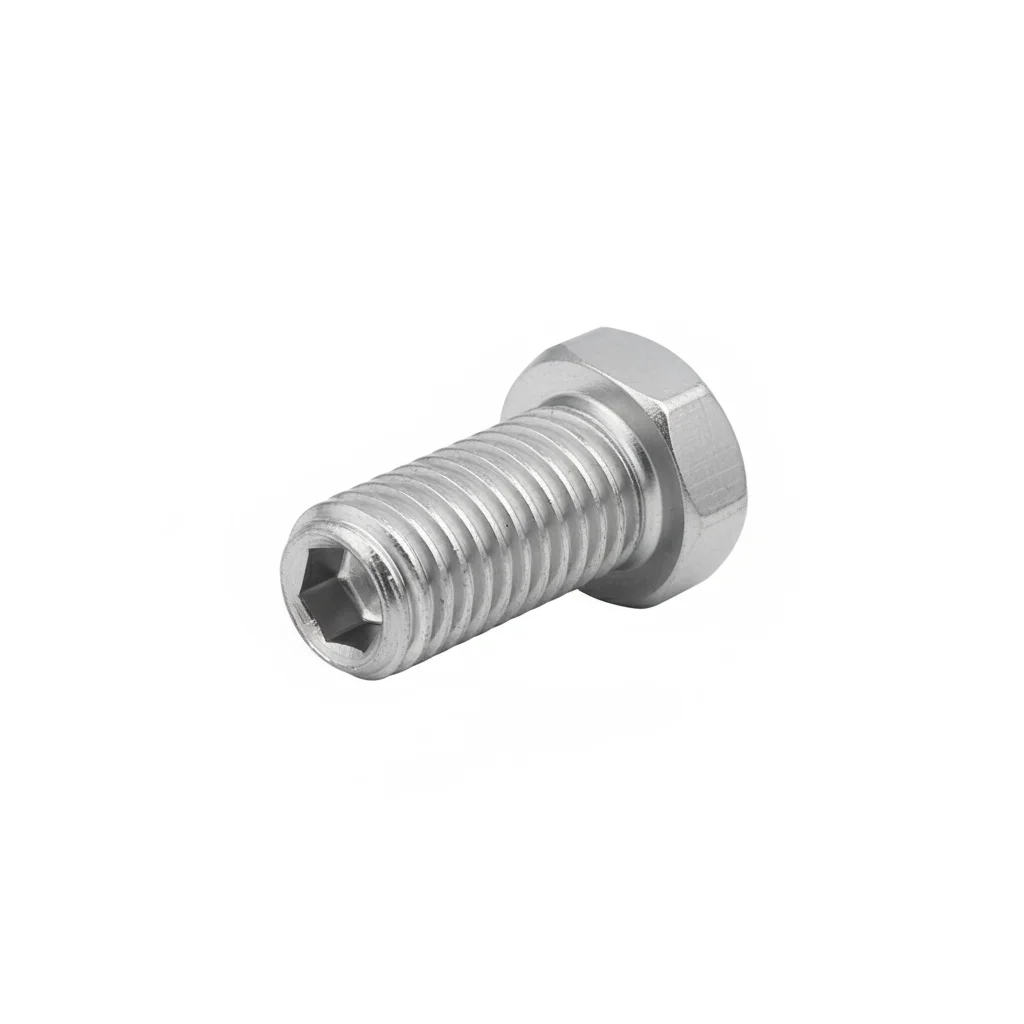
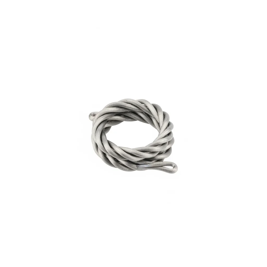
| M22×80 Track Bolt | Drive Wheel Ring Gear Bolt | Anti-Loosening Wire | |
|---|---|---|---|
| SPEC | Grade 12.9, phosphated anti-galling | M20×70, Grade 10.9 | Φ1.6, galvanized steel wire |
| MATERIAL | — | — | — |
| GRADE | Grade 12.9 | Grade 10.9 | — |
| FINISH | HDG >=55um per ISO 1461 | HDG >=55um per ISO 1461 | HDG >=55um per ISO 1461 |
| CORROSION | C3 (ISO 12944-2) | C3 (ISO 12944-2) | C3 (ISO 12944-2) |
| TEMP | -20°C to +80°C | -20°C to +80°C | -20°C to +80°C |
| WEIGHT | ~0.5 kg/piece | ~0.5 kg/piece | ~0.5 kg/piece |
| MOQ | 100 pcs | 100 pcs | 100 pcs |
| PACK | VCI paper + carton | VCI paper + carton | VCI paper + carton |
| STD | ISO 898-1, GB/T 3098.1 | ISO 898-1, GB/T 3098.1 | ISO 898-1, GB/T 3098.1 |
| USE | Phosphated anti-galling | Grade 10.9 | Galvanized steel wire |
PROCEDURE
- Thoroughly degrease the track plate bolt holes and mating surfaces with MEK solvent, and ensure the bolt threads are clean and free of debris.
- Apply anti-seize compound to the threads of the M22×80 Grade 12.9 phosphated bolts to prevent galling during installation, and place the galvanized anti-loosening wire through the bolt head holes.
- Insert the bolts and tighten them in a crisscross pattern using a torque wrench to the specified torque, ensuring the track plate is fully seated against the link.
- After all bolts are torqued, thread the anti-loosening wire through the bolt head holes in a figure-eight pattern and twist the ends tightly to secure the fasteners against impact-induced loosening.
- Inspect the wire for proper tension and verify no bolt head has rotated by checking the alignment marks made before torquing.
COMMON ERRORS
| ✕ WRONG | CONSEQUENCE | ✓ CORRECT |
|---|---|---|
| Installing track bolts without applying anti-seize compound, causing galling on the phosphated threads | Threads seize during torquing, leading to inaccurate preload, possible bolt fracture, and difficult future removal. | Always apply a high-quality anti-seize compound to the bolt threads before installation, especially in dusty or muddy track environments. |
| Failing to use the anti-loosening wire or reusing a damaged wire | Track bolts can loosen under impact loads from bulldozer or paver operation, causing track plate separation and severe equipment damage. | Always install a new galvanized anti-loosening wire (Φ1.6) in the proper figure-eight pattern, and inspect it for breaks during routine maintenance. |
MAINTENANCE
Inspect track bolts and anti-loosening wires at each service interval or after heavy impact operations; re-torque any bolt below 80% of specified torque. Replace bolts with corrosion pitting deeper than 0.3mm or if the phosphating is worn off. Check the wire for damage and replace if kinked or broken.
REFERENCED STANDARDS
Technical Basis and Reference Standards
Hydraulic fluid power - General rules and safety requirements for systems and their components
Alloy structural steelsHydraulic fluid power - General rules
GB/T 3098.1-2010Mechanical properties of fasteners - Bolts
JB/T 5947-2018Construction machinery - General technical specification for painting
SAE J1453:2019O-Ring Face Seal Fittings
SUPPLIER CAPABILITY
Quality, Delivery & Customization
Quality Control
- ✓MTC material certificates with every batch
- ✓Key parts sampled for hardness/salt spray/torque coefficient
- ✓100% inspection or AQL sampling before shipment
Delivery
- ✓Standard parts made to order: 7-15 days
- ✓Custom parts: 25-45 days
- ✓FOB/CIF/DDP supported
Customization
- ✓Drawing review and material matching
- ✓Non-standard sizes/heads/threads
- ✓Small-batch prototyping supported
Certification
- ✓Material certificates (MTC)
- ✓Spectrographic analysis reports
- ✓Salt spray test reports (on request)
MOQ: No MOQ for standard parts; custom parts assessed by process complexity
FAQ
Frequently Asked Questions
RELATED READING
Keep Reading & Next Step
BEYOND TECHNICAL SPECS
Finding the right factory, controlling quality, delivering on time — that's the real challenge. We cover fasteners, rubber, plastics, industrial textiles. One team, end to end.
SEE CAPABILITIES →