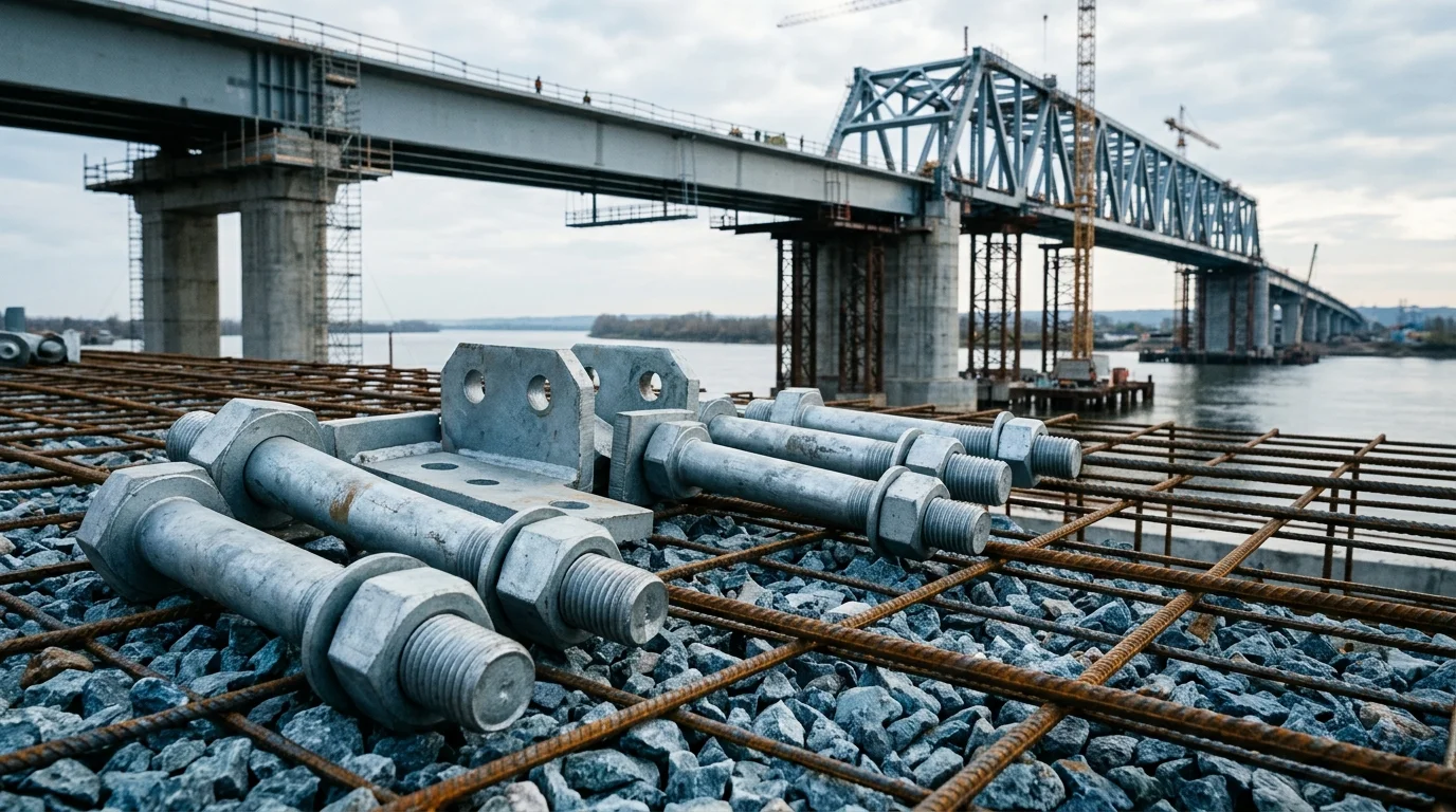
Steel Structure Factory Fasteners: High-Strength Bolts, Anchor Bolts, and Purlin Braces
Select the right connection method for main load-bearing joints, column base anchorage, and cladding systems. Compare friction-type high-strength bolts (M20/M24, 10. 9S) with anchor bolt and grout combinations (M30, Q345B). Includes slip coefficient requirements, pretension control, and corrosion protection per ISO 12944
RISK AUDIT // ENGINEERING DIAGNOSIS
Procurement Pitfall Guide
"Real-world pitfalls in steel structure fastener procurement and installation"
QC-AUDIT // REV.5
SCALE 1:1 · 03 ITEMS
RISK-01
Insufficient slip coefficient on friction surfaces leads to premature joint slippage
Corrective Measures
RISK-02
Insufficient or relaxed pretension in high-strength bolts
Corrective Measures
RISK-03
Anchor bolt positioning deviation and anchorage failure
Corrective Measures
FIELD-SPECIFIC INSIGHT
Critical Checks for Steel Structure Fastener Selection
Selecting the wrong connection method can lead to joint slippage, anchorage failure, or reduced seismic performance. The key differences between friction-type high-strength bolts and anchor bolt grout combinations lie in load transfer mechanism, installation precision, and corrosion protection requirements
WHAT TO CHECK
- 1Friction-type high-strength bolts require a slip coefficient ≥0. 45 (sandblasted to Sa2.5); paint or oil reduces coefficient below 0.2, causing premature slip at 50% design load
- 25° creates a gap under column base, leading to additional bending stress and concrete cracking under crane loads
- 3Torque deviations and creep can cause 15% loss after 3 months, reducing connection stiffness
- 4Dacromet coating is an alternative for high-strength bolts to avoid hydrogen embrittlement
| Check | Why it matters | What to specify |
|---|---|---|
| Slip coefficient test | Friction-type connections rely on friction; coefficient <0. 45 leads to joint slip under design load | Require one set of slip coefficient tests per 2000 bolts per GB 50205; minimum acceptable value 0. 45 |
| Pretension verification | Insufficient pretension reduces connection stiffness and causes slip under wind or crane loads | Use torque-controlled or torsion-shear type bolts; re-torque if below 80% |
| Anchor bolt embedment accuracy | 5° causes uneven load distribution and concrete cracking | Use template for placement; inspect before grouting |
| Corrosion protection for bolts | Corrosion reduces bolt section and can cause brittle failure; hydrogen embrittlement risk for high-strength bolts | For high-strength bolts, consider Dacromet or mechanical plating to avoid hydrogen embrittlement |
All test results and inspection records should be documented in the quality control report. For critical joints, consider additional non-destructive testing (e. G. , ultrasonic) for anchor bolt anchorage integrity
Evidence level: source-page-only
INDUSTRY TECH REFERENCE
The Rail-Creep Chain: Clip Bolts Stretch, the Rail Starts Gnawing
The crane runway is the one fastener subsystem in a factory that needs watching during service: every crane pass is a load cycle, and longitudinal rail creep stretches or shakes loose the hook and clip bolts. Follow the chain to the inspection points.
- 1Every crane pass is one load cycle — a typical fatigue analysis counts 100 passes/day × 300 days/year × 30 years ≈ 900,000 cycles, with an impact factor of 1.25 carried on the vertical wheel load entering the fatigue check (lateral force enters at 50% of full value)
- 2Longitudinal creep of the rail relative to the girder stretches or shakes loose the hook and clip bolts — the AISC journal is explicit that these connections must be inspected and maintained on a regular basis
- 3Bolts loosen or stretch → the rail fixing fails → the rail misaligns and starts gnawing — the field problem list also covers foundation settlement, misalignment from uneven wear, and environmental corrosion
- 4Gnawing and misalignment worsen the wheel-load distribution → local overload → the feedback accelerates, feeding the damage back into the rail and its fixings
- 5Crane girders are non-redundant load paths — a single fracture can collapse the runway; since the 1960s welded girders have failed in fatigue far more often than riveted ones, some after only 2-15 years of service, with cracks starting at the top-flange-to-web fillet welds and stiffener welds
- 6Intervention point: put clip and hook bolts on a scheduled inspection-and-retighten list — the opposite of the rest of the frame, which is maintenance-free after final tightening, this is the one subsystem in the factory's fasteners that needs watching during service
The 900,000 cycles are a textbook-calculated order-of-magnitude estimate (100 passes/day × 300 days/year × 30 years); the 1.25 impact factor and the lateral force at 50% of full value follow the AISE TR13 fatigue-analysis basis.
INDUSTRY TECH REFERENCE
Crane Rail Clip Bolts: 8.8 or 10.9?
Rail clip bolts are the directly procurable standard parts in crane-rail fixing. Lateral capacity tiers by grade, the lateral force starts from a wheel-load estimate, then the drawing set and the inspection rhythm close out the selection.
| Grade | Lateral capacity per clip | When to choose | Fitting and maintenance |
|---|---|---|---|
| Grade 8.8 (economic default) | 21-250 kN across the Gantrail bolted-clip range | First choice for normal duty; lighter lateral demand | Size against the 23G525 drawing set (replaces 05G525) |
| Grade 10.9 (higher lateral capacity) | 30-300 kN | Heavy lateral loads or heavy cranes; re-check the lateral force at about 15% of the vertical wheel load | Same drawing set; step up a grade when the lateral-capacity check fails |
| Lateral-force estimate | One clip carries the whole wheel's horizontal force, taken as about 15% of the vertical wheel load | Gantrail sizing rule — estimate first, then verify | Order-of-magnitude; re-check against the actual wheel load and impact factor |
| Maintenance rhythm | — | Watch for rail creep, loose or stretched bolts, and rail crawling | Clip and hook bolts must be inspected and retightened on a schedule (AISC journal requirement) |
The lateral force at about 15% of wheel load is an order-of-magnitude estimate; the per-clip lateral capacities of 21-250/30-300 kN are Gantrail full-series product data; 23G525 is the current standard atlas, replacing 05G525 and covering duty classes A1-A7 for cranes 5t-250t.
INDUSTRY TECH REFERENCE
Hours 1-48 After Final Tightening: The Preload-Decay Acceptance Window
Preload does not sit still after final tightening: most of the loss lands in the first hour, it stabilizes within a day or two, and it only stops after a month. Follow the timeline to see why acceptance is locked to the 1-48 h window.
- 1Assemblies are re-tested in batches on arrival — large hexagon heads: torque coefficient + wedge load + nut proof load; twist-off type: tightening axial force + wedge load + nut proof load; any failed batch is returned in full (a main-control item of GB 50205)
- 2Tightening runs as initial / re-tightening / final — the initial and re-tightening torques equal 50% of the final torque; the erection preload is taken as Pc = 1.1P — the roughly 10% preload loss is compensated once, at erection, not by re-tightening during service
- 3Most of the preload loss happens in the first hour after final tightening, stabilizes within a day or two, and stops after a month — which is why final-tightening quality checks are uniformly limited to the 1-48 h window
- 4Inside the window: re-check the final torque and count no more than 5% of twist-off splines left intact; miss the window and the preload you measure is no longer the final-tightened state
- 5Once accepted, main-frame joints are maintenance-free for life — the code system contains no in-service re-tightening clause: selling "maintenance-free" is correct, selling "re-tightenable" is wrong
- 6The one exception: crane-runway clip and hook bolts are the system's only in-service exception — they go on a scheduled inspection-and-retighten list and get no maintenance-free pass
No order-of-magnitude estimates are used in this slot.
INDUSTRY TECH REFERENCE
Torque Coefficient k: First Gate at Receiving, Three Field Traps
Under torque-controlled tightening the preload is converted entirely through the torque coefficient k — if k is off, the same wrench delivers an unknowable preload. Lock the numbers at receiving, then guard three field traps.
- Torque-controlled tightening converts preload as T_c = k·P_c·d — with a bad k, too low slips and too high drives into yield
- Re-test on arrival: torque coefficient mean 0.110-0.150 with standard deviation ≤0.0100 for high-strength large hexagon assemblies (JGJ 82-2011 Table 6.3.1) — any failed batch is returned in full
- Watch the metric change: GB/T 1231-2024 already switched the scatter indicator from "standard deviation" to "coefficient of variation (CV)" — accept new assemblies against the new standard, while the JGJ 82 values remain the current construction-code basis
- The three field traps: damaged or contaminated threads, privately added lubricant or anti-seize, and counterfeit parts entering the supply chain — all directly change k (field case: an A325 snapped at 1-2% under a calibrated Skidmore wrench, with over-torque / lubrication shifting k / counterfeits as the three suspected causes)
- Consequence chain: k scatter → insufficient preload → friction-surface slip → the joint switches to bearing-type action → hole-wall bearing and bolt shear → connection deformation; or preload too high → plastic elongation → preload decays or the bolt snaps outright
The 1-2% snap rate is an order-of-magnitude estimate, for trend judgment; the torque coefficient 0.110-0.150 with σ≤0.0100 and the full-batch rejection rule are standard acceptance values.
INDUSTRY TECH REFERENCE
Column-Base Anchor Bolts: Three Red Lines — No Shear, Q235B, Grout Hard Numbers
Column-base anchors rarely fail from a lack of strength — they fail on positioning, grouting, and the shear division of labor. Set the three red lines first, then talk about the rest.
- Shear division of labor: column-base anchor bolts should not be relied on for the horizontal reaction at the column base — that force is carried by friction between the base plate and concrete (friction coefficient can be taken as 0.4) or by a shear key (GB 50017-2017 §12.7.4)
- Material and anchorage: non-load-bearing anchors should be Q235B; anchorage length should be no less than 20d; for d>40mm weld an anchor plate at the end and use an anchorage length of no less than 12d (note to GB 50017-2017 §12.7.6)
- Positioning tolerance: anchor center deviation ≤2.0mm, and no negative deviation on exposed length or thread length (GB 50205-2020 §10.2) — this is where nuts that cannot take full threads come from
- Secondary grouting must use cement-based grout (GB/T 50448-2015 Table 4.1.1): 28-day compressive strength ≥50MPa for Class I and ≥60MPa for Classes II-IV; zero bleeding; chloride <0.1%; vertical expansion ratio 0.1-0.35% at 3h
- Failure chain: shrinkage cracking of ordinary cement mortar → moisture ingress → anchor corrosion with reduced section → pullout under wind or seismic loads; placement is a three-way trade-off: embedded J-type bolts are cheap but position poorly, post-drilling positions well but may hit rebar, and a reserved pocket plus grout is economical but epoxy-grout filling is expensive
No order-of-magnitude estimates are used in this slot.
INDUSTRY TECH REFERENCE
The 2025 Standard-Merger Wave: The Four-Piece Assembly Unifies — Stale Numbers Bite
For factory steel-structure fasteners the first move on standards is confirming the current edition — this subdomain just went through a merger wave, and a stale standard number on a purchase order or drawing is an instant defect.
The listed standards are current public editions, cited by number and scope for procurement navigation only; acceptance values follow the current published texts. No order-of-magnitude estimates are used in this slot.
PLAN COMPARISON
Three-Plan Core Parameter Comparison
Compare row by row. Click column headers to jump to plan details.
| A · Plan A · High-Strength Bolt Friction-Type Connection | B · Plan B · Anchor Bolt and Grout Combination | C · Plan C · Purlin Tie Rod and Sag Bolt | |
|---|---|---|---|
| 1. M20 LARGE HEX HIGH-STRENGTH BOLT | |||
| SPEC | 10.9S, GB/T 1231 | Q345B, hook type | Q235B, hot-dip galvanized |
| MATERIAL | — | Q345B | Q235B |
| FINISH | HDG >=55um per ISO 1461 | HDG >=55um per ISO 1461 | HDG >=55um per ISO 1461 |
| 2. M24 TENSION CONTROL HIGH-STRENGTH BOLT | |||
| SPEC | 10.9S, GB/T 3632 | Flowability ≥ 300mm | Grade 4.8, zinc-plated |
| GRADE | — | — | Grade 4.8 |
| FINISH | HDG >=55um per ISO 1461 | HDG >=55um per ISO 1461 | HDG >=55um per ISO 1461 |
| 3. FRICTION SURFACE ABRASIVE BLASTING | |||
| SPEC | Slip coefficient ≥ 0.45 | Q235B, δ=20mm | δ=3mm, stamped |
| MATERIAL | — | Q235B | Q235B |
| FINISH | HDG >=55um per ISO 1461 | HDG >=55um per ISO 1461 | HDG >=55um per ISO 1461 |
SELECTION GUIDE
How to choose the connection method based on structural parts?
| Operating condition | Recommended option | Key basis |
|---|---|---|
| Main load-bearing joints with seismic design (main beam-column joint / truss connection) | Option A: high-strength friction-type bolts — M20 large hex high-strength bolt (10.9S, GB/T 1231) + M24 tension control high-strength bolt (10.9S, GB/T 3632); friction surface abrasive blasting, slip coefficient ≥ 0.45 | GB/T 1231-2024; GB/T 3632; C3 corrosion category per ISO 12944-2 |
| Column base anchorage / equipment foundation fixing | Option B: anchor bolts + grouting — M30×1500 anchor bolt (Q345B, hook type) + CGM high-strength grout (flowability ≥ 300mm) + leveling shim plate (Q235B, δ=20mm) | GB/T 799-2020 anchor bolts; C4 harsh per ISO 12944-2 |
| Cladding system / secondary components (roof cladding / wall system) | Option C: purlin tie rod and sag bolt — Φ12 round steel tie rod (Q235B, hot-dip galvanized) + M12×40 sag bolt (Grade 4.8, zinc-plated) + Z-section purlin connector plate (Q235B, δ=3mm, stamped) | CECS 102:2018; C3 per ISO 12944-2 |
Plan A · High-Strength Bolt Friction-Type Connection
C3 corrosion category per ISO 12944-2
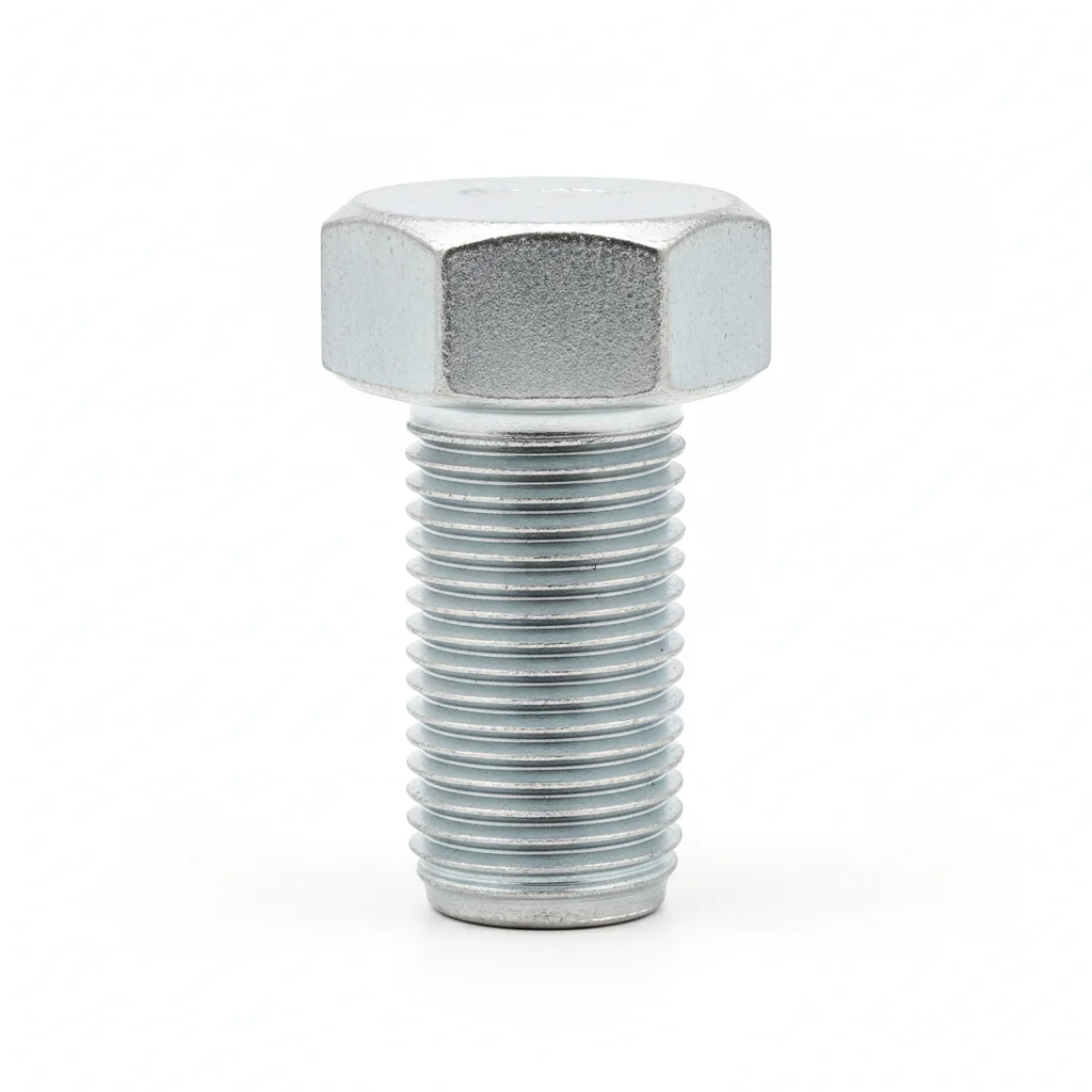
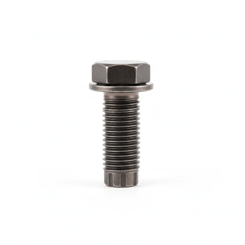
| M20 Large Hex High-Strength Bolt | M24 Tension Control High-Strength Bolt | Friction Surface Abrasive Blasting | |
|---|---|---|---|
| SPEC | 10.9S, GB/T 1231 | 10.9S, GB/T 3632 | Slip coefficient ≥ 0.45 |
| MATERIAL | — | — | — |
| GRADE | — | — | — |
| FINISH | HDG >=55um per ISO 1461 | HDG >=55um per ISO 1461 | HDG >=55um per ISO 1461 |
| CORROSION | C3 (ISO 12944-2) | C3 (ISO 12944-2) | C3 (ISO 12944-2) |
| TEMP | -20°C to +80°C | -20°C to +80°C | -20°C to +80°C |
| WEIGHT | ~0.5 kg/piece | ~0.5 kg/piece | ~0.5 kg/piece |
| MOQ | 100 pcs | 100 pcs | 100 pcs |
| PACK | VCI paper + carton | VCI paper + carton | VCI paper + carton |
| STD | ISO 898-1, GB/T 3098.1 | ISO 898-1, GB/T 3098.1 | ISO 898-1, GB/T 3098.1 |
| USE | GB/T 1231 | GB/T 3632 | Friction surface abrasive blasting |
PROCEDURE
- Abrasive-blast the faying surfaces to Sa2.5 to achieve a slip coefficient of at least 0.45, then install bolts within 2 hours before re-contamination.
- Place the M20 or M24 high-strength bolt with washers under both head and nut, ensuring alignment within the tolerance allowed by GB/T 1231 or GB/T 3632.
- Perform initial tightening with a torque wrench to about 50% of the final torque, then final tightening in a star pattern to the specified pretension, verifying with a calibrated wrench.
- Within 48 hours, re-inspect the final torque on at least 10% of the bolts; any bolt below the required pretension must be re-tightened and marked.
- After final tightening, apply torque seal paint across the nut-bolt joint and record the installation date and batch for traceability.
COMMON ERRORS
| ✕ WRONG | CONSEQUENCE | ✓ CORRECT |
|---|---|---|
| Painting or oiling the friction surfaces before assembly | The slip coefficient drops below 0.2, causing the joint to slip at 50% of the design load and leading to premature connection failure. | Keep the faying surfaces bare and blast them to Sa2.5 just before installation; do not apply paint or lubricant to these areas. |
| Using ordinary bolts instead of 10.9S high-strength bolts | The connection lacks the required pretension and friction capacity, resulting in slippage and reduced seismic performance. | Verify the grade marking (10.9S) and use only bolts conforming to GB/T 1231 or GB/T 3632 for friction-type connections. |
| Skipping the torque verification step after installation | Torque relaxation can reduce pretension by 15% within months, leading to joint slip under wind or crane loads. | Re-check torque on at least 10% of bolts within 48 hours and re-tighten any that are below the required value. |
MAINTENANCE
Inspect high-strength bolt joints at each overhaul window, checking for paint seal cracks or loosening. Re-torque any bolt that has lost more than 15% of its pretension (detected by torque check). Replace bolts showing corrosion pitting deeper than 0.3mm or affecting more than 5% of the surface. For critical joints, perform a full torque audit at least once per year and document results in the CMMS.
Plan B · Anchor Bolt and Grout Combination
C4 Harsh per ISO 12944-2
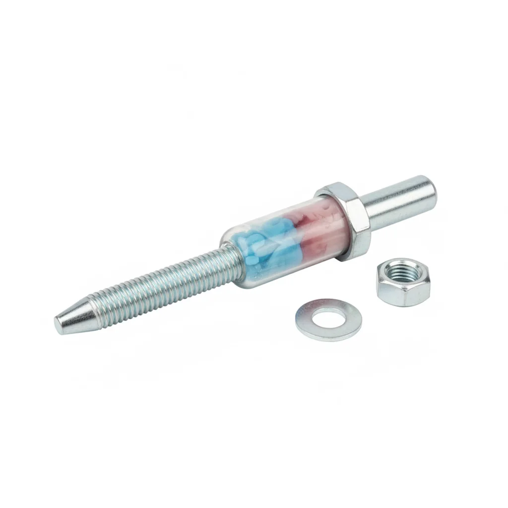
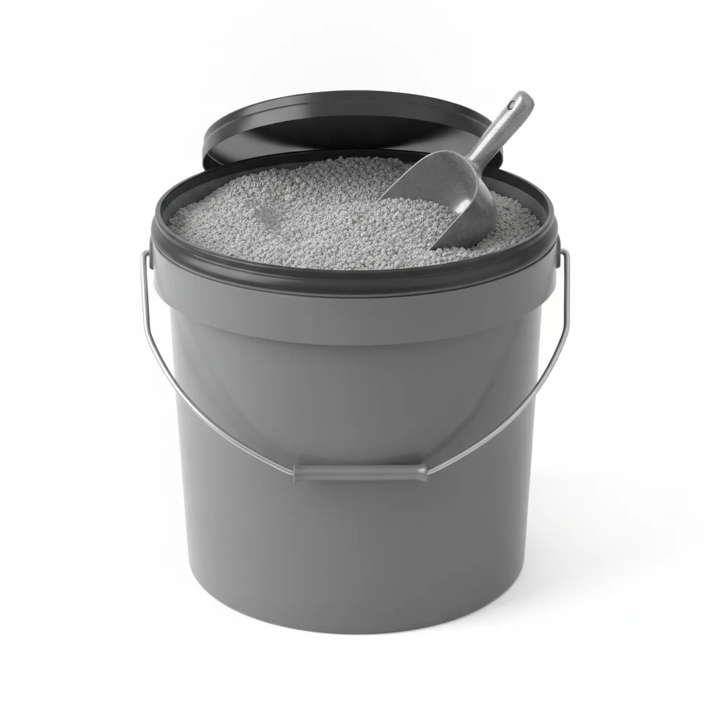
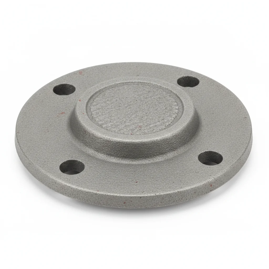
| M30×1500 Anchor Bolt | CGM High-Strength Grout | Leveling Shim Plate | |
|---|---|---|---|
| SPEC | Q345B, hook type | Flowability ≥ 300mm | Q235B, δ=20mm |
| MATERIAL | Q345B | — | Q235B |
| GRADE | — | — | — |
| FINISH | HDG >=55um per ISO 1461 | HDG >=55um per ISO 1461 | HDG >=55um per ISO 1461 |
| CORROSION | C3 (ISO 12944-2) | C3 (ISO 12944-2) | C3 (ISO 12944-2) |
| TEMP | -20°C to +80°C | -20°C to +80°C | -20°C to +80°C |
| WEIGHT | ~0.5 kg/piece | ~0.5 kg/piece | ~0.5 kg/piece |
| MOQ | 100 pcs | 100 pcs | 100 pcs |
| PACK | VCI paper + carton | VCI paper + carton | VCI paper + carton |
| STD | ISO 898-1, GB/T 3098.1 | ISO 898-1, GB/T 3098.1 | ISO 898-1, GB/T 3098.1 |
| USE | Hook type | CGM high-strength grout | δ=20mm |
PROCEDURE
- Set the anchor bolt group with a positioning template, holding center deviation within ±5mm and verticality within 0.5° before pouring concrete.
- After concrete has cured, place the Q235B leveling shim plate (δ=20mm) on the foundation and level it precisely to receive the column base.
- Position the column base over the M30×1500 Q345B hook-type anchor bolts; level with the shim plates and snug the nuts.
- Form a dam around the base plate and pour CGM high-strength grout (flowability ≥300mm) in one continuous operation, venting to avoid voids.
- After grout has hardened, perform final tightening of the anchor bolt nuts to the specified torque in a cross-pattern sequence.
- Apply the specified epoxy coating to the exposed bolt threads and grout surface to meet the C4 harsh corrosion protection requirement.
COMMON ERRORS
| ✕ WRONG | CONSEQUENCE | ✓ CORRECT |
|---|---|---|
| Anchoring bolts without a positioning template, allowing center deviation beyond the ±5mm limit. | A 3mm gap develops under the column base, adding bending stress to the bolts and cracking the anchorage concrete under crane loads. | Use a positioning template and welded lattice frame to hold the bolt group; re-measure and adjust before pouring concrete. |
| Grouting in layers or with interruptions, trapping air or leaving the base plate voided. | Incomplete grout support reduces load capacity and can lead to grout crushing or bolt fatigue under cyclic loads. | Pour the CGM grout in one continuous operation from one side, using a low-pressure pump if needed to ensure flowability ≥300mm and full contact. |
MAINTENANCE
Inspect anchor bolt torque and grout condition at each overhaul window; re-torque any bolt that has lost more than 15% tension and repair cracks with epoxy resin.
Plan C · Purlin Tie Rod and Sag Bolt
C3 (ISO 12944-2)
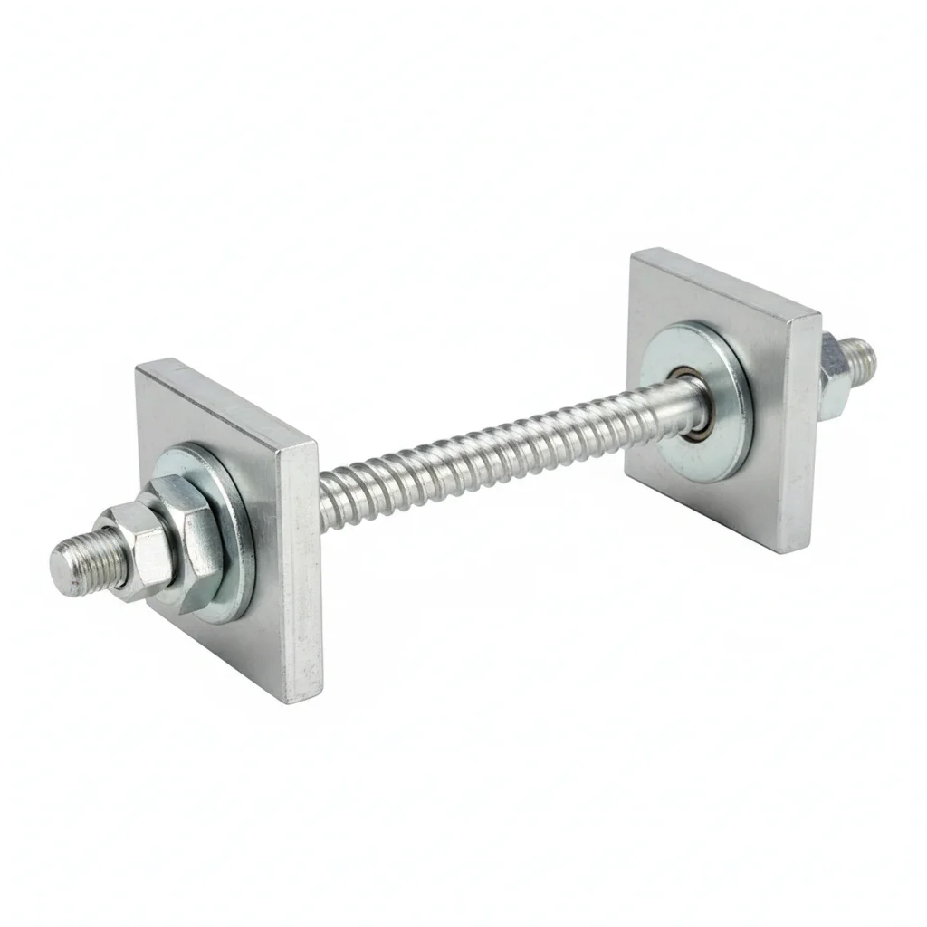
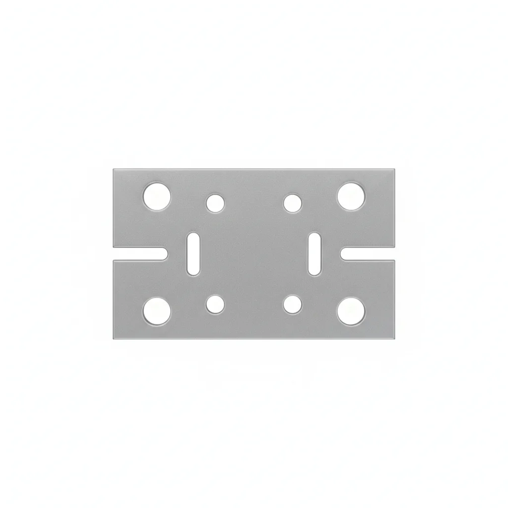
| Φ12 Round Steel Tie Rod | M12×40 Sag Bolt | Z-Section Purlin Connector Plate | |
|---|---|---|---|
| SPEC | Q235B, hot-dip galvanized | Grade 4.8, zinc-plated | δ=3mm, stamped |
| MATERIAL | Q235B | — | Q235B |
| GRADE | — | Grade 4.8 | — |
| FINISH | HDG >=55um per ISO 1461 | HDG >=55um per ISO 1461 | HDG >=55um per ISO 1461 |
| CORROSION | C3 (ISO 12944-2) | C3 (ISO 12944-2) | C3 (ISO 12944-2) |
| TEMP | -20°C to +80°C | -20°C to +80°C | -20°C to +80°C |
| WEIGHT | ~0.5 kg/piece | ~0.5 kg/piece | ~0.5 kg/piece |
| MOQ | 100 pcs | 100 pcs | 100 pcs |
| PACK | VCI paper + carton | VCI paper + carton | VCI paper + carton |
| STD | ISO 898-1, GB/T 3098.1 | ISO 898-1, GB/T 3098.1 | ISO 898-1, GB/T 3098.1 |
| USE | Hot-dip galvanized | Zinc-plated | Stamped |
PROCEDURE
- Lay out and pre-assemble the Φ12 Q235B hot-dip galvanized tie rods along the purlin run, checking that the lengths match the actual spacing.
- Attach the Z-section purlin connector plates (δ=3mm) to the purlins at the marked positions using the M12×40 Grade 4.8 zinc-plated sag bolts.
- Insert the tie rod ends through the connector plate holes and secure with nuts, adjusting the rod tension to remove slack.
- Tighten all sag bolts and tie rod nuts to a snug fit, ensuring the cladding line remains straight and true.
- Verify that all galvanized surfaces are free from damage; touch up any scratched areas with a zinc-rich paint to maintain the ≥55μm coating.
COMMON ERRORS
| ✕ WRONG | CONSEQUENCE | ✓ CORRECT |
|---|---|---|
| Using ordinary bolts instead of the specified Grade 4.8 sag bolts for purlin bracing. | The lower strength bolts may shear under wind or thermal loads, causing the purlin system to lose stability and the cladding to distort. | Use M12×40 Grade 4.8 zinc-plated sag bolts as specified, and torque them to the recommended value. |
| Over-tightening the tie rod nuts, bending the connector plate or stripping the threads. | A bent plate or damaged threads reduce the load path and may lead to premature failure of the bracing system. | Tighten the nuts only to a snug fit, and use a torque wrench to avoid exceeding the yield of the Grade 4.8 bolts. |
MAINTENANCE
Check tie rod tension and sag bolt tightness seasonally, and re-tighten any sag bolts that have loosened by more than 80% of the specified torque.
SPEC MATRIX
Product Specifications Covered for This Scenario
Specifications from the Yaxiio product catalog. Weights are theoretical calculated values.
| DIA | LENGTH | MATERIAL | GRADE | FINISH | SKU | UNIT WEIGHT |
|---|---|---|---|---|---|---|
| M12 | 30, 35, 40, 45, 50, 60, 70, 80 | Alloy Steel | 10.9S | Black Oxide | 8 | 42–86 g |
| M16 | 40–120 (10 sizes) | Alloy Steel | 10.9S | Black Oxide | 10 | 98–220 g |
| M20 | 45–160 (11 sizes) | Alloy Steel | 10.9S | Black Oxide | 11 | 180–460 g |
| M24 | 50–200 (12 sizes) | Alloy Steel | 10.9S | Black Oxide | 12 | 300–830 g |
| M30 | 60–240 (12 sizes) | Alloy Steel | 10.9S | Black Oxide | 12 | 570–1500 g |
REFERENCED STANDARDS
Technical Basis and Reference Standards
Standard for Design of Steel Structures
High Strength Large Hexagon Head Bolts for Steel StructuresTechnical Specification for High-Strength Bolt Connections in Steel Structures
GB/T 1231-2024High Strength Large Hexagon Head Bolts for Steel Structures
GB/T 799-2020Anchor Bolts
CECS 102:2018Technical Specification for Steel Structures of Light-Weight Buildings with Gabled Frames
SUPPLIER CAPABILITY
Quality, Delivery & Customization
Quality Control
- ✓MTC material certificates with every batch
- ✓Key parts sampled for hardness/salt spray/torque coefficient
- ✓100% inspection or AQL sampling before shipment
Delivery
- ✓Standard parts made to order: 7-15 days
- ✓Custom parts: 25-45 days
- ✓FOB/CIF/DDP supported
Customization
- ✓Drawing review and material matching
- ✓Non-standard sizes/heads/threads
- ✓Small-batch prototyping supported
Certification
- ✓Material certificates (MTC)
- ✓Spectrographic analysis reports
- ✓Salt spray test reports (on request)
MOQ: No MOQ for standard parts; custom parts assessed by process complexity
FAQ
Frequently Asked Questions
RELATED READING
Keep Reading & Next Step
BEYOND TECHNICAL SPECS
Finding the right factory, controlling quality, delivering on time — that's the real challenge. We cover fasteners, rubber, plastics, industrial textiles. One team, end to end.
SEE CAPABILITIES →