Tensioning Frame & Roller Fasteners
The slide rail bolt loosens under alternating tension, the rail tilts, roller axis deflects 1-2°, belt runs off, edge wears 15-20mm in 3 months. Jack screw loosening causes bearing outer ring rotation, housing bore wear. Select correct grade, coating, and torque maintenance to prevent these failure chains.
RISK AUDIT // ENGINEERING DIAGNOSIS
Purchasing Pitfall Guide
"Bolt loosening on the tensioning frame doesn't announce itself—it shows up as belt edge wear and a rail that's no longer square."
QC-AUDIT // REV.5
SCALE 1:1 · 03 ITEMS
RISK-01
Tensioning Rail Bolts Loosen Under Alternating Tension, Causing Roller Misalignment
Corrective Measures
RISK-02
Risk of Fastener Fatigue Fracture
Corrective Measures
RISK-03
Installation Torque Decay Leading to Misalignment
Corrective Measures
FIELD-SPECIFIC INSIGHT
Failure Chain: From Bolt Loosening to Belt Scrap
The most overlooked failure path in conveyor tensioning frames is not the belt or bearing itself, but the fasteners that secure the slide rail and bearing housing. A single M20 bolt losing preload to 30% after 10⁴ cycles triggers a cascade: rail tilt → roller misalignment → belt edge wear → width loss → reduced load capacity → belt scrapping.
WHAT TO CHECK
- 1Slide rail bolts (M16-M30) experience alternating shear forces up to tens of kN; preload decays to 30% after 10⁴ cycles, causing 1-2° roller axis deflection.
- 2Bearing housing jack screws (M8-M12) lock the bearing outer ring; loosening allows ring rotation, wearing housing bore and scrapping the housing.
- 3Initial installation torque of 120 N·m decays to 80 N·m after 100 hours (33% loss), requiring re-torque if below 80% of specified torque.
- 4Corrosion affecting >5% surface area or pitting depth >0.3mm mandates replacement; HDG >=55µm per ISO 1461 is specified for all plans.
- 5Inspection every 250 operating hours or 6 months; full disassembly of 20% sample every 3 years; replace all critical fasteners every 5 years.
| Check | Why it matters | What to specify |
|---|---|---|
| Bolt preload retention | Preload decay to 30% after 10⁴ cycles causes rail tilt and belt misalignment | Specify 10.9 or 12.9 grade bolts; require torque audit at 250h intervals; replace if below 80% of specified torque |
| Jack screw locking | Loosening allows bearing outer ring rotation, wearing housing bore | Use wedge lock washers or thread-locking compound; inspect every 250h |
| Corrosion protection | Corrosion >5% area or pitting >0.3mm reduces fastener strength | HDG >=55µm per ISO 1461; for C5-M use 316L jack screws |
| Torque decay rate | 33% decay in 100h leads to 0.5mm roller axis deviation | Re-torque at 250h; maximum allowable tension loss 15% |
Data based on conveyor tensioning frame application; actual fatigue life depends on belt tension, stroke length, and environmental conditions. Verify with OEM or field measurements.
Evidence level: source-page-only
INDUSTRY TECH REFERENCE
Tension Calculation & Take-Up Acceptance: Match These Standards First
Before RFQing or accepting a take-up assembly (slide rails, take-up screws, counterweights), line up the references first: which standard calculates tension, which governs whole-machine acceptance, and what mandates slip detection underground. Navigation only — no clauses reproduced.
The listed standards are all public standards, shown by number and scope for procurement navigation only; specific acceptance values follow the current standard text. No order-of-magnitude estimates are used in this slot.
INDUSTRY TECH REFERENCE
From a Loose Jack Screw to a Chewed Belt Edge: How Drift Turns Irreversible
When the take-up frame's jack screws and bracket bolts loosen, the first casualty is rarely the bolt itself — it is the belt edge. Walk the chain: every step has a verifiable interception point; at the end, the repair cost jumps from 'one jack screw' to 'a full hot-vulcanized splice'.
- 1Start — loose fixings: bearing-housing jack screws and idler-frame bolts work loose, or loading is off-center — a common root cause of belt drift; check the fasteners before blaming the belt
- 2Drift: the belt runs off the centerline and the edge grinds against the structure — a non-perpendicular or seized idler, off-center loading, or an untrue splice can all trigger it; the mechanism sits with the idlers and the take-up
- 3Wear accumulates: the edge keeps grinding, the width thins and load-bearing section is lost — a chronic process with an early inspection window, so act before it becomes visible
- 4Critical tier: edge-running damage on a steel-cord belt is critical — severe damage mandates hot-vulcanized repair
- 5The repair is asset-heavy: vulcanizing needs dedicated hot-press equipment and skilled crews, and long important conveyors are recommended for X-ray on-line monitoring — repair is not a matter of swapping one bolt
- 6Cost and interception: a belt change means days of stoppage — the backdrop of every purchasing decision; the first step in drift control is aligning the idlers and retightening the brackets/jack screws, not replacing the belt
No order-of-magnitude estimates are used in this slot.
INDUSTRY TECH REFERENCE
Export Orders for Take-Up Hardware: Add a “Calculation Basis” Line to the Spec
Take-up screws and slide-rail bolts answer to no national product standard in the US market; spec authority sits with OEMs and distribution networks. Put the calculation and acceptance basis into the spec line on export RFQs, so an 'equivalent replacement' cannot quietly downgrade the part.
- No federal yardstick: the US has no national product standard for bulk-material belting, and the RMA recommendations gave way to ARPM specifications from 2011 — spec authority sits with the OEM/distribution system; anchor the RFQ spec line with the calculation references (e.g. ISO 5048 for tension, GB/T 10595 for whole-machine acceptance)
- North American hard compliance: power or gravity inclined conveyors at metal/nonmetal mines require a backstop or brake (30 CFR 56.14113) — put the backstop connection bolts that travel with take-up and drive orders into the RFQ, not 'let's decide on arrival'
- 'Equivalent replacement' is a real trap: field cases show substitute parts with marginal specs (friction performance, etc.) collapsing joint life — demand measured data before approving a supplier switch, and reject verbal equivalents
No order-of-magnitude estimates are used in this slot.
PLAN COMPARISON
Three-Plan Core Parameter Comparison
Compare row by row. Click column headers to jump to plan details.
| A · A·Standard | B · B·Large Long-Distance | C · Plan C · Heavy Load/Dusty Environment | |
|---|---|---|---|
| 1. SLIDE RAIL BOLT | |||
| SPEC | M16-M24 | M20-M30 | M20-M30 |
| MATERIAL | 42CrMo | 42CrMoA | 42CrMoA |
| GRADE | 10.9 Dacromet | 12.9 | 12.9 |
| FINISH | HDG >=55um per ISO 1461 | HDG >=55um per ISO 1461 | HDG >=55um per ISO 1461 |
| 2. BEARING HOUSING JACK SCREW | |||
| SPEC | M8-M12 | M8-M12 | M8-M12 |
| MATERIAL | 45# Steel | 304 | 316L |
| FINISH | HDG >=55um per ISO 1461 | HDG >=55um per ISO 1461 | HDG >=55um per ISO 1461 |
A·Standard
C3 per ISO 12944-2, hot-dip galvanized ≥55 µm per ISO 1461
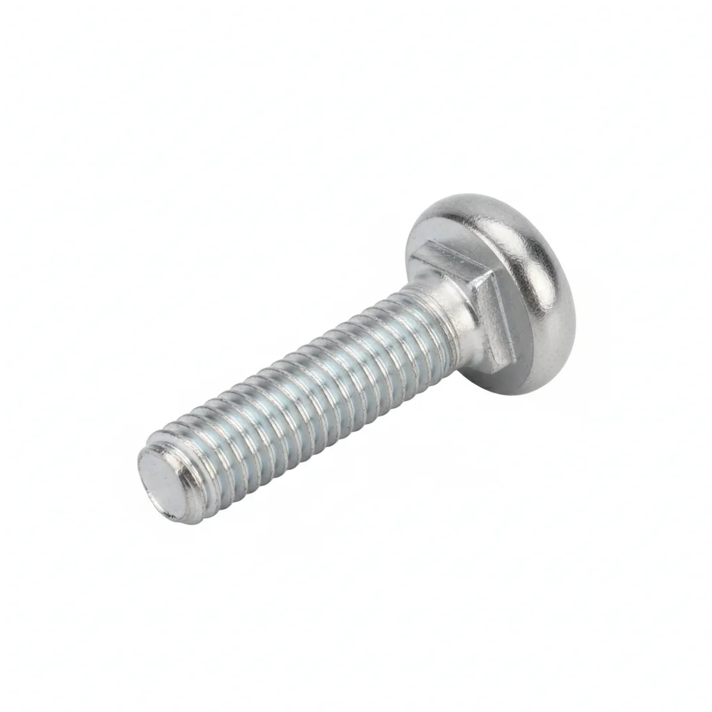
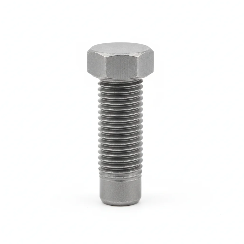
| Slide Rail Bolt | Bearing Housing Jack Screw | |
|---|---|---|
| SPEC | M16-M24 | M8-M12 |
| MATERIAL | 42CrMo | 45# Steel |
| GRADE | 10.9 Dacromet | — |
| FINISH | HDG >=55um per ISO 1461 | HDG >=55um per ISO 1461 |
| CORROSION | C3 (ISO 12944-2) | C3 (ISO 12944-2) |
| TEMP | -20°C to +80°C | -20°C to +80°C |
| WEIGHT | ~0.5 kg/piece | ~0.5 kg/piece |
| MOQ | 100 pcs | 100 pcs |
| PACK | VCI paper + carton | VCI paper + carton |
| STD | ISO 898-1, GB/T 3098.1 | ISO 898-1, GB/T 3098.1 |
| USE | Tensioning Rail Fixing | Bearing Outer Ring Locking |
PROCEDURE
- Clean the slide rail mounting surface and bolt holes with solvent; verify flatness within 0.1 mm per 100 mm using a straightedge.
- Position the M16–M24 10.9 bolt with a hardened flat washer under the head and a double nut (jam nut plus primary nut) on the threaded side.
- Align the tensioning rail precisely; use a laser alignment tool to check the roller axis perpendicularity to the belt centerline, adjusting until deviation is <1/1000.
- Tighten the primary nut in a star pattern to a torque consistent with a 10.9 M20 bolt under C3 conditions, then snug the jam nut against it and torque the jam nut to the same value.
- After final tightening, weld a small anti-loosening stop block to the rail adjacent to the nut to mechanically lock rotation.
- Mark the nut and bolt with torque seal paint; record the torque values and alignment readings in the QA log.
COMMON ERRORS
| ✕ WRONG | CONSEQUENCE | ✓ CORRECT |
|---|---|---|
| Using a single nut instead of the specified double-nut configuration on the slide rail bolt | The bolt preload decays to 30% after 10⁴ cycles, the rail tilts, and the roller axis deflects 1–2°, causing belt edge wear of 15–20 mm within 3 months. | Install two nuts (jam nut plus primary) and torque both to specification; optionally weld a stop block for triple locking. |
| Skipping the laser alignment check after tightening the slide rail bolts | A misaligned roller axis (deviation >1/1000) leads to progressive belt runout and uneven edge wear. | Use a theodolite or laser alignment tool to verify perpendicularity to the belt centerline; adjust as needed before locking. |
MAINTENANCE
At each quarterly belt runout inspection, check slide rail bolt torque on a 5% sample and re-torque any bolt below 80% of specified torque. Replace bolts with corrosion affecting >5% of surface area or pitting >0.3 mm. Inspect jack screws for looseness by sound (hollow vs. solid) and re-tighten if loose. Annually measure the tensioning screw diameter; replace if necking exceeds 0.5 mm. Every 3 years, disassemble and inspect 20% of fasteners; every 5 years, replace all critical fasteners regardless of condition.
B·Large Long-Distance
C4 Harsh per ISO 12944-2
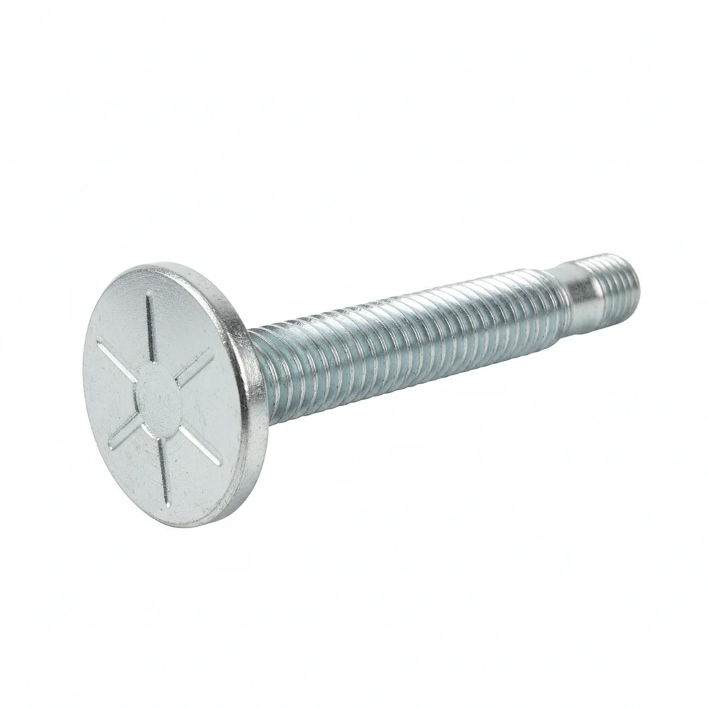
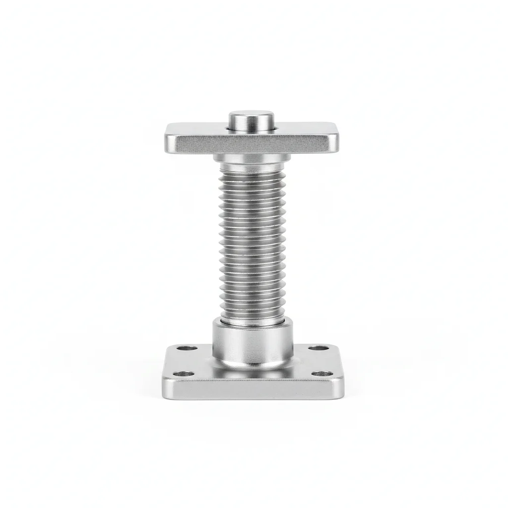
| Slide Rail Bolt | Jack Screw | |
|---|---|---|
| SPEC | M20-M30 | M8-M12 |
| MATERIAL | 42CrMoA | 304 |
| GRADE | 12.9 | — |
| FINISH | HDG >=55um per ISO 1461 | HDG >=55um per ISO 1461 |
| CORROSION | C3 (ISO 12944-2) | C3 (ISO 12944-2) |
| TEMP | -20°C to +80°C | -20°C to +80°C |
| WEIGHT | ~0.5 kg/piece | ~0.5 kg/piece |
| MOQ | 100 pcs | 100 pcs |
| PACK | VCI paper + carton | VCI paper + carton |
| STD | ISO 898-1, GB/T 3098.1 | ISO 898-1, GB/T 3098.1 |
| USE | Long-Distance High Tension Conveyor | Food/Humid Environment |
PROCEDURE
- Degrease the slide rail and housing mounting faces with acetone, then verify surface roughness Ra < 3.2 μm to ensure full metal-to-metal contact for the 12.9-grade M20-M30 bolts.
- Coat the threads of the 42CrMoA slide rail bolts and the 304 jack screws with an anti-seize compound rated for the -20°C to +80°C operating range before assembly.
- Position the slide rail bolts with wedge lock washers under the nut; for the jack screws, apply thread-locking compound to prevent loosening from vibration.
- Use a laser alignment tool to set the roller axis perpendicular to the belt centerline (deviation < 1/1000), then tighten the slide rail bolts in a cross-pattern to the specified torque, verifying 10% with a calibrated torque wrench.
- After tensioning, check the jack screws for secure seating; torque them to specification and mark with paint for visual verification.
- Record environmental conditions (temperature, humidity) and torque values in the maintenance log for future reference.
COMMON ERRORS
| ✕ WRONG | CONSEQUENCE | ✓ CORRECT |
|---|---|---|
| Using 304 jack screws in a chloride-rich environment where pitting can occur | Pitting corrosion initiates on the jack screw, leading to seizure or premature failure within the first year of service. | For humid or food-grade environments, select 316L jack screws or apply a protective coating to the 304 grade to resist chloride attack. |
| Over-tightening the slide rail bolts beyond the elastic limit of the 12.9 grade | The bolt may yield or fracture under alternating tension, causing sudden loss of preload and rail misalignment. | Follow the specified torque values and use a calibrated torque wrench; verify with a torque audit after the first 250 operating hours. |
MAINTENANCE
Inspect the slide rail bolts and jack screws every 250 operating hours or at each overhaul window, whichever comes first. Re-torque any fastener that has lost more than 20% of its specified torque (i.e., below 80% of the initial value). Replace fasteners showing corrosion over 5% of their surface area or with pitting deeper than 0.3 mm. Every 3 years, perform a full disassembly and inspection of a 20% sample of critical fasteners. Every 5 years, replace all critical fasteners regardless of condition. Document all findings in the CMMS with date and inspector ID.
Plan C · Heavy Load/Dusty Environment
C5-M Extreme per ISO 12944-2
| Slide Rail Bolt | Jack Screw | |
|---|---|---|
| SPEC | M20-M30 | M8-M12 |
| MATERIAL | 42CrMoA | 316L |
| GRADE | 12.9 | — |
| FINISH | HDG >=55um per ISO 1461 | HDG >=55um per ISO 1461 |
| CORROSION | C3 (ISO 12944-2) | C3 (ISO 12944-2) |
| TEMP | -20°C to +80°C | -20°C to +80°C |
| WEIGHT | ~0.5 kg/piece | ~0.5 kg/piece |
| MOQ | 100 pcs | 100 pcs |
| PACK | VCI paper + carton | VCI paper + carton |
| STD | ISO 898-1, GB/T 3098.1 | ISO 898-1, GB/T 3098.1 |
| USE | Extreme Conditions / Maximum Protection | Extreme Conditions / Maximum Protection |
PROCEDURE
- Degrease mounting surfaces with MEK solvent and verify surface roughness Ra < 1.6 μm to maximize the fatigue life of the 12.9-grade M20-M30 slide rail bolts under heavy alternating loads.
- Apply a marine-grade anti-corrosion compound rated from -50°C to 200°C to all threads and contact faces of the 42CrMoA bolts and 316L jack screws.
- For the slide rail bolts, use PTFE-encapsulated washers to reduce friction and ensure consistent preload; for the jack screws, apply a high-strength thread-locking adhesive.
- Align the roller axis to within 0.3 mm using laser alignment, then tighten the slide rail bolts with a hydraulic tensioner to achieve precise preload; verify 10% of bolts with PMI (Positive Material Identification) to confirm 42CrMoA grade.
- Perform dye penetrant testing on 10% of the critical fasteners to detect any surface cracks; replace any fastener showing indications.
- Apply a protective sealant over the bolt heads and jack screws to prevent dust ingress, and install permanent condition monitoring instrumentation on the tensioning frame.
COMMON ERRORS
| ✕ WRONG | CONSEQUENCE | ✓ CORRECT |
|---|---|---|
| Using uncoated 316L jack screws in a dusty, abrasive environment where they can gall during installation | Galling can seize the jack screw, making future adjustments impossible and leading to bearing housing damage. | Use anti-seize compound during installation and ensure the 316L jack screws are properly lubricated to prevent galling. |
| Neglecting to verify the actual material grade of the slide rail bolts before installation | Substituting a lower grade bolt could lead to fatigue fracture under extreme loads, causing catastrophic belt misalignment and downtime. | Perform PMI on a sample of bolts to confirm 42CrMoA composition before installation, and document the results for the compliance audit. |
MAINTENANCE
Inspect all critical fasteners at each overhaul window or every 250 operating hours, whichever comes first. Re-torque any fastener that has lost more than 20% of its specified torque. Replace any fastener with corrosion affecting over 5% of its surface area or pitting deeper than 0.3 mm. Every 3 years, disassemble and inspect a 20% sample of fasteners for fatigue cracks; every 5 years, replace all critical fasteners regardless of condition. Document all inspections in the CMMS with date, inspector ID, and corrective actions taken.
SELECTION GUIDE
Choosing the Right Tensioning Fastener
| Operating condition | Recommended option | Key basis |
|---|---|---|
| General application — C3 per ISO 12944-2, hot-dip galvanized ≥55µm per ISO 1461 | Plan A · Standard: slide rail bolt M16-M24 (42CrMo, 10.9 grade Dacromet) + bearing housing jack screw M8-M12 (45# steel) | ISO 5048 conveyor design; DIN 22101 belt conveyor design; ISO 1461 hot-dip galvanizing ≥55µm |
| Large long-distance conveyor — high tension | Plan B · Large Long-Distance: slide rail bolt M20-M30 (42CrMoA, 12.9 grade) + jack screw M8-M12 (304 for food/humid environment) + wedge lock washer | C4 per ISO 12944-2; ISO 5048 conveyor design; DIN 22101 |
| Extreme — mining/port heavy load + dust (C5-M per ISO 12944-2) | Plan C: slide rail bolt M20-M30 (42CrMoA, 12.9 grade) + jack screw M8-M12 (316L) + wedge lock washer + IP65 sealed bearing | C5-M per ISO 12944-2; GB/T 10595 belt conveyor |
| Alternating tension on tensioning rail bolts — tensioning stroke 500-2000mm, M20 bolt preload decays to 30% after 10⁴ cycles, roller axis deflects 1-2°, belt runs off and the belt edge wears 15-20mm in 3 months | Use 10.9 grade + double nuts + welded anti-loosening stop block for triple locking; laser alignment with perpendicularity deviation <1/1000; measure belt runout quarterly — adjust immediately if >1% of belt width | ISO 5048 conveyor design; DIN 22101 belt conveyor design |
| Torque decay and fatigue under alternating tension — initial installation torque 120 N·m decays to 80 N·m after 100 hours (33% loss, 0.5mm roller axis deviation); micro-cracks after an average of 5000 cycles, fracture probability 15% | Use lock washers + thread-locking adhesive for torque retention ≥90% after 1000 hours; high-strength alloy steel with enhanced surface treatment for fatigue life >20000 cycles; re-torque at 250 hours; maximum allowable tension loss 15% | GB/T 10595 belt conveyor; DIN 22101 belt conveyor design |
REFERENCED STANDARDS
References
SUPPLIER CAPABILITY
Quality, Delivery & Customization
Quality Control
- ✓MTC material certificates with every batch
- ✓Key parts sampled for hardness/salt spray/torque coefficient
- ✓100% inspection or AQL sampling before shipment
Delivery
- ✓Standard parts made to order: 7-15 days
- ✓Custom parts: 25-45 days
- ✓FOB/CIF/DDP supported
Customization
- ✓Drawing review and material matching
- ✓Non-standard sizes/heads/threads
- ✓Small-batch prototyping supported
Certification
- ✓Material certificates (MTC)
- ✓Spectrographic analysis reports
- ✓Salt spray test reports (on request)
MOQ: No MOQ for standard parts; custom parts assessed by process complexity
FAQ
FAQ
RELATED READING
Keep Reading & Next Step
NEXT: SELECTION & RFQ
Belt Joint & Pulley Lagging FastenersFollow this page's selection path to the same-scenario RFQ page.
RELATED TOPIC
Chain & Tensioning FastenersRELATED TOPIC
Idler Bearing HousingBEYOND TECHNICAL SPECS
Finding the right factory, controlling quality, delivering on time — that's the real challenge. We cover fasteners, rubber, plastics, industrial textiles. One team, end to end.
SEE CAPABILITIES →