Bracing Cable Connection Bolt Fracture Prevention
In rare earthquakes, column bracing axial forces can exceed design values by 2-3 times. If connection bolt load capacity safety factor is insufficient or installation torque deviation exceeds 20%, bolt shear fracture leads to bracing failure and potential collapse. GB 50011 requires bracing connections to be designed for no-yield performance under major earthquakes — bolt specification one grade higher than bracing section capacity (overstrength factor ≥1.2). Use torque wrench during installation and spot-check 20% of torque during construction acceptance
FIELD-SPECIFIC INSIGHT
Seismic Connection Bolt Overstrength Checkpoints
The most overlooked engineering difference in bracing cable connections is the overstrength requirement: bolts must be designed to yield after the bracing member, not before. This means bolt grade and torque must be specified to match the bracing capacity, not just static loads
WHAT TO CHECK
- 1Bolt grade: Specify one grade higher than bracing section capacity (overstrength factor ≥1.2) to ensure bolt yields after bracing under rare earthquakes
- 2Installation torque: Use torque wrench and spot-check 20% of bolts during acceptance
- 3Corrosion protection: Match coating to environment (e.g., HDG for C3, stainless steel for coastal)
- 4Maintenance: Inspect every 6 months; re-torque any fastener below 80% of specified torque; replace if corrosion affects >5% surface area or pitting depth >0.3mm
| Check | Why it matters | What to specify |
|---|---|---|
| Bolt grade vs bracing capacity | Under rare earthquakes, axial force can be 2-3 times design value; bolt must yield after bracing to avoid brittle fracture | Overstrength factor ≥1.2; bolt specification one grade higher than bracing section capacity per GB 50011 |
| Installation torque deviation | — | Use torque wrench; spot-check 20% of bolts; maximum deviation 20% |
| Corrosion protection level | Corrosion reduces bolt effective area, lowering load capacity and increasing fracture risk | For coastal or extreme environments, consider stainless steel or Dacromet |
| Maintenance interval and criteria | Undetected corrosion or loosening can lead to progressive failure | Inspect every 6 months; re-torque below 80%; replace if corrosion >5% area or pitting >0.3mm; full disassembly every 3 years; replace all critical fasteners every 5 years |
Data based on GB 50011 seismic design requirements and ISO 12944 corrosion environments. Actual overstrength factor and torque limits must be verified per project structural calculations
Evidence level: standard-backed
RISK AUDIT // ENGINEERING DIAGNOSIS
Procurement Pitfall Avoidance Guide
"Bracing cable connections face harsh realities: seismic overloads, corrosion, and installation errors that can lead to collapse."
QC-AUDIT // REV.5
SCALE 1:1 · 03 ITEMS
RISK-01
Column bracing connection bolts fracture first during major earthquakes
Corrective Measures
RISK-02
Corrosion protection mismatched with actual environment
Corrective Measures
RISK-03
Anchor bolt positioning deviation
Corrective Measures
INDUSTRY TECH REFERENCE
Bracing Node Bolts in Two Tiers: Seismic-Critical vs Secondary Ties
Bracing is part of the factory's lateral-load path, so node bolts split into two tiers by what they carry: seismic-critical bracing nodes use high-strength friction-type connections, while secondary ties bear through ordinary bolts. Match the tier before RFQing — one spec does not fit all.
| Node tier | Connection set and grade | Load path and key parameters |
|---|---|---|
| Seismic-critical node (bracing-to-frame joint) | 10.9S/8.8S high-strength hex connection set or twist-off (TC) type, M20-M30 | Friction-type slip resistance; design preload P=155-355 kN at grade 10.9; torque coefficient 0.110-0.150 (std dev σ≤0.0100) |
| Secondary bracing tie (purlin/wall-tie class) | C-grade ordinary bolt, grade 4.6/4.8 | Bearing-type load transfer (non-friction); hole dia. d+1.0-1.5 mm; maintained with the primary structure |
No order-of-magnitude estimates are used in this slot.
INDUSTRY TECH REFERENCE
Galvanizing Rules by Bolt Grade: A325 May, A490 May Not
Corrosive environments often call for hot-dip galvanizing on bracing and frame bolts — but the grade decides whether galvanizing is allowed: the 8.8 class (US grade A325) can, the A490 class cannot. State grade and coating together on the RFQ to stay clear of the delayed-fracture zone.
| Bolt grade | Hot-dip galvanizing allowed? | Line and cautions |
|---|---|---|
| Quenched-and-tempered grade 10.9 (incl. 10.9S) | Hydrogen-embrittlement sensitive | Electroplating/acid-pickling hydrogen ingress + yield-zone preload = a delayed-fracture breeding ground; indicative -20°C impact energy ≥27 J at grade 10.9 (GB/T 3098.1 system) |
| F3125 Grade A325 (≈class 8.8, 120 ksi) | Yes (F2329) | The common tier for corrosive environments; consolidated into F3125 in 2016 — 'A325' still works on the RFQ, cite F3125 in the spec |
| F3125 Grade A490 (≈class 10.9, 150 ksi) | No (neither F2329 nor B695) | Only F3393 zinc-aluminum coating is allowed; writing HDG into an A490 RFQ plants a guaranteed nonconformance |
The ≥27 J impact energy at -20°C is an indicative example value for grade 10.9, to be checked against the official standard text; A325 corresponds roughly to Grade 8.8 and A490 to Grade 10.9. No order-of-magnitude estimates are used in this slot.
INDUSTRY TECH REFERENCE
Purchasing Discipline for HS Connection Sets: Whole-Lot Retest, Lot Binding, Single-Use
Since 2025-04-01 the hex connection-set product standard has been consolidated into GB/T 1231-2024 (fully replacing the four 2006 part standards), so citing the old numbers in contracts or drawings is a hard defect. Around that gate, the buying side watches four gates: batch retest, lot binding, single-use tightening, and the temporary-bolt ban.
- Batch retest, whole-lot rejection on failure: hex connection sets are retested on torque coefficient + wedge load + nut proof load; twist-off (TC) sets on fastener axial force + wedge load + nut proof load — a control item under GB 50205-2020, and the institutional source of the '0.01 out = whole batch returned' rule
- Lot-matched supply, no mixing: bolts, nuts and washers ship boxed by batch and are drawn per day's use on site (JGJ 82 §6.4.6) — the supplier's lot-management capability is a hard selection criterion
- Single-use tightening, no in-service re-torquing: snug, re-tightening and final passes should finish within one day, and the check completes within 1h-48h after final tightening; the whole system carries no in-service re-tightening clause — sell 'maintenance-free', never 're-tightenable'
- HS bolts must not serve as temporary bolts: a connection set used as a temporary bolt carries a loading history that shifts its torque coefficient — common at bracing install sites; ask how the site tightening sequence runs at intake
No order-of-magnitude estimates are used in this slot.
INDUSTRY TECH REFERENCE
Four QC Sensitivities on the High-Strength Bolt Site
Most bracing-node HS bolt failures are planted in the construction window: calibrated wrenches, site lubricants, genuine versus counterfeit supply, and friction-surface condition. Four sensitivities, four interception points — written into the installation briefing they cost far less than rework later.
- Calibrated wrench: on a bridge retrofit site, A325 bolts under Skidmore-calibrated wrenches still showed a 1-2% breakage rate, and failures occurred only on the reamed old-girder connections — check all three root causes (overtorque, lubricant shifting k, counterfeit parts) instead of blaming the wrench alone
- Site lubrication: thread damage or contamination shifts the torque coefficient sharply, and shop-applied oil or anti-seize changes k just the same — the fitters' first instinct is to ask 'what is on these threads?', and the retest is judged against the as-tightened condition
- Genuine supply: beware counterfeit parts entering legitimate supply chains — 'a big contractor does not guarantee genuine parts' — intake retest is the only gate
- Friction-surface condition: coated surfaces give μ of only 0.15 (alkyd iron-red) vs 0.35 (inorganic zinc-rich), a near-3x gap — 'paint it, then tension the HS bolts' is a classic site mistake; grind no less than 4x the bolt-hole diameter, perpendicular to the load direction, and never work in the rain
The 1-2% breakage rate is an order-of-magnitude estimate, for trend judgment; the μ 0.15/0.35 values, the ≥4×-diameter grind and the no-work-in-rain rule are standard clause values.
PLAN COMPARISON
Three-Plan Core Parameter Comparison
Compare row by row. Click column headers to jump to plan details.
| A · Plan A · Standard Type | B · Plan B · Reinforced Type | C · Plan C · Premium Type | |
|---|---|---|---|
| 1. GALVANIZED STEEL STRAND | |||
| SPEC | φ6-20mm | For φ6-20mm | M12-M24 |
| MATERIAL | Galvanized Steel Wire | Q235B | Q235B |
| FINISH | HDG >=55um per ISO 1461 | HDG >=55um per ISO 1461 | HDG >=55um per ISO 1461 |
Plan A · Standard Type
C3 (ISO 12944-2) with HDG ≥55μm per ISO 1461
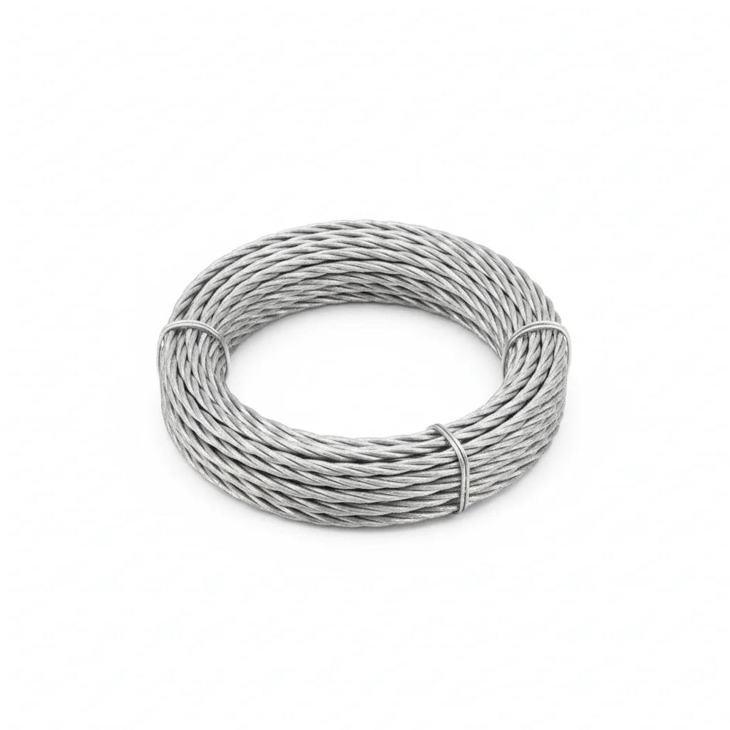
| Galvanized Steel Strand | |
|---|---|
| SPEC | φ6-20mm |
| MATERIAL | Galvanized Steel Wire |
| GRADE | — |
| FINISH | HDG >=55um per ISO 1461 |
| CORROSION | C3 (ISO 12944-2) |
| TEMP | -20°C to +80°C |
| WEIGHT | ~0.5 kg/piece |
| MOQ | 100 pcs |
| PACK | VCI paper + carton |
| STD | ISO 898-1, GB/T 3098.1 |
| USE | Factory Steel Structure |
PROCEDURE
- Clean the bracing cable ends and connection plate with solvent; verify contact surfaces are free of oil, rust, and burrs.
- Align the bracing cable with the column gusset plate; insert the 10.9S grade bolts and hand-tighten with washers in place.
- Tighten bolts diagonally in three passes using a torque wrench; for each pass increase torque progressively to final value, keeping deviation within ±5%.
- Spot-check 20% of installed bolts with a calibrated torque wrench during construction acceptance; confirm no bolt is below the required torque.
- Mark each tightened bolt with a torque seal paint line across head, washer, and nut; record torque values in the installation QA log.
COMMON ERRORS
| ✕ WRONG | CONSEQUENCE | ✓ CORRECT |
|---|---|---|
| Using ordinary bolts instead of 10.9S grade high-strength bolts | Under rare earthquakes, axial force can reach 2-3 times design value; ordinary bolts shear-fracture prematurely, causing bracing failure and possible collapse. | Specify 10.9S grade bolts with overstrength factor ≥1.2 relative to bracing capacity as required by GB 50011. |
| Tightening bolts in a circular pattern from one side | Uneven preload distribution leads to torque deviation exceeding 20%, reducing connection stiffness and increasing fracture risk during seismic events. | Tighten diagonally in three steps, controlling final torque deviation within ±5% per procedure. |
| Omitting torque verification after installation | Undetected under-torqued bolts may loosen under cyclic load, accelerating fatigue and shear failure. | Use a torque wrench and spot-check 20% of bolts during construction acceptance as required. |
MAINTENANCE
Inspect bracing connections seasonally and after any seismic event; re-torque any bolt found below 80% of specified torque; replace bolts showing corrosion over 5% of surface area or pitting deeper than 0.3mm, and verify torque coefficient (standard deviation ≤0.010) for 10.9S grade bolts.
Plan B · Reinforced Type
C4 Harsh per ISO 12944-2
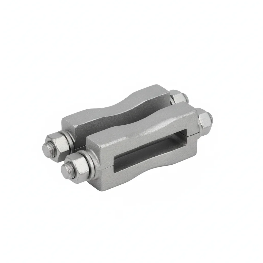
| Steel Strand Lock Clip | |
|---|---|
| SPEC | For φ6-20mm |
| MATERIAL | Q235B |
| GRADE | — |
| FINISH | HDG >=55um per ISO 1461 |
| CORROSION | C3 (ISO 12944-2) |
| TEMP | -20°C to +80°C |
| WEIGHT | ~0.5 kg/piece |
| MOQ | 100 pcs |
| PACK | VCI paper + carton |
| STD | ISO 898-1, GB/T 3098.1 |
| USE | Factory Steel Structure |
PROCEDURE
- Degrease the lock clip contact faces with acetone to remove mill oil; verify surface roughness Ra below 3.2 μm using a profilometer.
- Apply an anti-corrosion joint compound rated for service temperatures between -20°C and +80°C; use PTFE-coated washers where specified for the Q235B clip.
- Position the Steel Strand Lock Clip on the bracing cable, aligning the strand within the clip grooves; tighten bolts in a cross-pattern sequence to the specified torque, then verify 10% with a calibrated torque wrench.
- Perform a pull-test on a 5% random sample of clips to 80% of the proof load; replace any clip that slips below the acceptance threshold and record results.
- Apply a weatherproof protective coating over all exposed clip surfaces and install corrosion monitoring coupons adjacent to critical joints for periodic assessment.
COMMON ERRORS
| ✕ WRONG | CONSEQUENCE | ✓ CORRECT |
|---|---|---|
| Tightening the lock clip bolts in a single pass without cross-pattern sequence | Uneven preload across the clip causes strand slippage under seismic load, leading to bracing slack and reduced lateral restraint. | Tighten bolts in a cross-pattern sequence in three incremental passes, using a torque wrench to control deviation within ±5%. |
| Using a lower-grade bolt than 10.9S for the lock clip connection | Bolt shear fracture occurs before the bracing member yields under rare earthquakes, causing sudden bracing failure. | Specify 10.9S grade bolts with an overstrength factor ≥1.2 relative to the bracing section capacity, per GB 50011. |
MAINTENANCE
Inspect lock clips at each overhaul window or seasonally; re-torque any clip bolt below 80% of specified torque, replace clips with corrosion affecting >5% of surface area or pitting depth >0.3mm, and perform full disassembly inspection on a 20% sample every 3 years.
Plan C · Premium Type
C5-M Extreme per ISO 12944-2
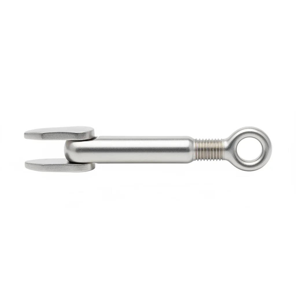
| Turnbuckle Bolt | |
|---|---|
| SPEC | M12-M24 |
| MATERIAL | Q235B |
| GRADE | — |
| FINISH | HDG >=55um per ISO 1461 |
| CORROSION | C3 (ISO 12944-2) |
| TEMP | -20°C to +80°C |
| WEIGHT | ~0.5 kg/piece |
| MOQ | 100 pcs |
| PACK | VCI paper + carton |
| STD | ISO 898-1, GB/T 3098.1 |
| USE | Factory Steel Structure |
PROCEDURE
- Degrease the turnbuckle threads and mating surfaces with MEK solvent; verify surface roughness Ra below 1.6 μm to ensure proper sealing.
- Apply marine-grade anti-corrosion compound rated for -50°C to +200°C on all threads and contact faces; use PTFE-encapsulated washers under both the turnbuckle body and locking nuts.
- Thread the turnbuckle onto the bracing cable ends, ensuring engagement length meets specification; tighten to the target preload using a hydraulic tensioner, then PMI-verify a 10% sample of hardware for material grade.
- Perform dye penetrant NDT on 10% of the turnbuckle assemblies; replace any component showing crack indications.
- Apply a protective sealant over all exposed threads and fasteners; install permanent condition monitoring instrumentation on the bracing system and file a compliance report with the regulatory authority.
COMMON ERRORS
| ✕ WRONG | CONSEQUENCE | ✓ CORRECT |
|---|---|---|
| Setting turnbuckle pre-tension below 15% of the strand breaking force | Steel strand goes slack under horizontal seismic forces, causing bracing to lose effectiveness and increasing P-Δ effects. | Use a dynamometer to verify pre-tension is between 15-20% of the strand breaking force, adjusting the turnbuckle as needed. |
| Using standard galvanized hardware in a C5-M coastal environment | Rapid corrosion reduces the effective cross-section of the turnbuckle, leading to premature failure under cyclic loading. | Select stainless steel or Dacromet-coated hardware for extreme environments, as per ISO 12944 C5-M classification. |
MAINTENANCE
Inspect turnbuckle assemblies at each overhaul window or seasonally; verify pre-tension with a dynamometer, re-torque any fastener below 80% of specified torque, replace components with corrosion affecting >5% surface area or pitting depth >0.3mm, and conduct a full disassembly inspection of a 20% sample every 3 years.
SELECTION GUIDE
Choosing the right bracing connection plan depends on your seismic zone and corrosion environment.
| Operating condition | Recommended option | Key basis |
|---|---|---|
| Inland dry area, low corrosivity (C1-C3 per ISO 12944-2) | Plan A · Standard Type: galvanized steel strand φ6-20mm (galvanized steel wire) with hot-dip galvanizing ≥55μm | ISO 12944-2 (C1-C3: hot-dip galvanizing ≥65μm); ISO 1461 hot-dip galvanized coatings |
| Coastal or corrosive environment (C4 Harsh per ISO 12944-2) | Plan B · Reinforced Type: steel strand lock clip (Q235B, for φ6-20mm); use Dacromet or stainless steel in C4-C5 | ISO 12944-2 (C4-C5: Dacromet or stainless steel); GB 50017 steel structure design |
| Extreme/special conditions (C5-M Extreme per ISO 12944-2) | Plan C · Premium Type: turnbuckle bolt M12-M24 (Q235B) | ISO 12944-2 C5-M; GB/T 20118 steel wire ropes; GB 50011 seismic design |
| Seismic zone: rare earthquake axial force 2-3 times design value | Bolt specification one grade higher than bracing section capacity (overstrength factor ≥1.2); Grade 10.9S bolts tightened diagonally in three steps, torque deviation within ±5%; spot-check 20% of torque at acceptance | GB 50011 (no-yield connections under major earthquakes); GB 50017-2017 high-strength bolt connections |
| Installation and maintenance across all environments | Use torque wrench and spot-check 20% of bolts at acceptance; inspect every 6 months; re-torque below 80% of specified torque; replace if corrosion affects >5% surface area or pitting depth >0.3mm; full disassembly every 3 years; replace critical fasteners every 5 years | GB 50011; ISO 12944-2 corrosion environments |
SUPPLIER CAPABILITY
Quality, Delivery & Customization
Quality Control
- ✓MTC material certificates with every batch
- ✓Key parts sampled for hardness/salt spray/torque coefficient
- ✓100% inspection or AQL sampling before shipment
Delivery
- ✓Standard parts made to order: 7-15 days
- ✓Custom parts: 25-45 days
- ✓FOB/CIF/DDP supported
Customization
- ✓Drawing review and material matching
- ✓Non-standard sizes/heads/threads
- ✓Small-batch prototyping supported
Certification
- ✓Material certificates (MTC)
- ✓Spectrographic analysis reports
- ✓Salt spray test reports (on request)
MOQ: No MOQ for standard parts; custom parts assessed by process complexity
FAQ
FAQ
RELATED READING
Keep Reading & Next Step
NEXT: SELECTION & RFQ
Bracing & Anti-Corrosion HardwareFollow this page's selection path to the same-scenario RFQ page.
RELATED TOPIC
Bracing and Anti-Corrosion HardwareRELATED TOPIC
Crane Rail FastenersBEYOND TECHNICAL SPECS
Finding the right factory, controlling quality, delivering on time — that's the real challenge. We cover fasteners, rubber, plastics, industrial textiles. One team, end to end.
SEE CAPABILITIES →