Crane Rail Fastener Failure Risks
A complete crane rail fastening set covers three component groups: rail clamps with Grade 10.9 bolts (M20–M24), rail joint fishplate bolts (Grade 12.9, M16 on heavy-duty cranes), and a crane buffer stop at each rail end. Specifications are matched to rail type and crane duty, with a full BOM per project available for review. Bridge cranes travel back and forth on crane rails hundreds of times a day—rail clamps firmly secure the rail to the crane beam, bearing the crane's wheel load, lateral horizontal force, and longitudinal braking force. One loose rail clamp bolt → lateral rail displacement → change in track gauge → crane wheel flange rubs against the rail side → both rail and wheel are scrapped. More dangerously: several failed rail clamps → rail is 'pushed' off the crane beam by the crane → the entire crane falls from mid-air.
RISK AUDIT // ENGINEERING DIAGNOSIS
Procurement Pitfall Guide
"Common pitfalls when sourcing crane rail fasteners"
QC-AUDIT // REV.5
SCALE 1:1 · 03 ITEMS
RISK-01
Rail clamp bolts loosen under repeated crane rolling
Corrective Measures
RISK-02
Rail joint fishplate bolt shearing causes joint step
Corrective Measures
RISK-03
Fatigue cracking of rail fixing base welds
Corrective Measures
FIELD-SPECIFIC INSIGHT
Critical Checkpoints for Crane Rail Fastener Procurement
The most overlooked engineering difference in crane rail fasteners is the fatigue life of fishplate bolts under repeated shear impact. While rail clamp bolts are often specified with Grade 10.9, fishplate bolts at rail joints require Grade 12.9 to resist 2-3 times static load impact. Additionally, wedge locking washers are essential for heavy-duty cranes to prevent preload loss from pulsed tensile stress.
WHAT TO CHECK
- 1Fishplate bolts at rail joints: Grade 12.9 required to withstand 2-3x static load impact; Grade 10.9 may shear under repeated cycles.
- 2Rail clamp bolts: preload decays over 40% after 3-5 years under 100,000 pulses/year; monthly torque inspection and wedge locking washers mitigate loosening.
- 3Corrosion protection: HDG >=55µm per ISO 1461 for C3/C4; for C5 coastal/seismic, full Dacromet + 304 stainless steel + wedge locking washers.
- 4Maintenance schedule: inspect every 250 operating hours or 6 months; replace fasteners with >5% corrosion or pitting depth >0.3mm; full replacement every 5 years.
| Check | Why it matters | What to specify |
|---|---|---|
| Bolt grade for fishplate joints | Fishplate bolts endure repeated shear stress; Grade 10.9 may fatigue and shear, causing rail step and crane jolting. | Specify Grade 12.9 per ISO 898-1 for all fishplate bolts. |
| Anti-loosening for rail clamp bolts | Pulsed tensile stress from crane passes reduces preload over time, leading to rail displacement and gauge change. | Use wedge locking washers (M20-M24) for heavy/extra heavy cranes; specify Dacromet coating for corrosion resistance. |
| Corrosion protection level | Corrosion reduces bolt strength and accelerates fatigue; pitting depth >0.3mm requires replacement. | HDG >=55µm per ISO 1461 for C3/C4; for C5, specify full Dacromet + 304 stainless steel. |
| Elastic base plate bolts for vibration | Vibration and thermal expansion can loosen standard bolts; disc springs compensate and maintain preload. | Specify alloy steel + disc spring bolts (Grade 10.9) for heavy-duty or seismic applications. |
All torque values and inspection intervals must be verified against the crane manufacturer's manual and site conditions. Maximum allowable tension loss: 15%.
Evidence level: source-page-only
INDUSTRY TECH REFERENCE
The Three Fatigue Load Components on Crane Girders: How Each Is Counted
Fatigue analysis of the crane-girder–rail system does not take every load at full value: vertical wheel load, lateral side force, and longitudinal braking force each have their own basis. Design, acceptance, and re-checks all take numbers the same way.
| Load component | Value used in fatigue analysis | Where it lands on the fasteners |
|---|---|---|
| Vertical wheel load | Impact factor 1.25 included | Every crane pass counts as one load cycle; the wheel load transfers through the rail to the clamp/hook bolts as repeated tension |
| Lateral side force | 50% of full value enters the analysis | One clamp carries all the horizontal force of one wheel — estimate the selection side force at 15% of the vertical wheel load |
| Longitudinal braking force | Per the AISE TR13 basis | Longitudinal force lands on the rail-to-girder connection; clamp/hook bolts need periodic inspection to catch creep-driven loosening or stretch |
The lateral side force at about 15% of the vertical wheel load is an order-of-magnitude estimate; the 1.25 impact factor and the lateral force at 50% of full value follow the AISE TR13 fatigue-analysis basis.
INDUSTRY TECH REFERENCE
Rail Clamp Bolts by Grade: Lateral Capacity, 8.8 vs 10.9
Estimate the lateral demand first: one clamp carries all the horizontal force of one wheel, hand-estimated at 15% of the vertical wheel load (Gantrail selection basis). Size against the capacity table — do not default to the highest grade.
| Grade | Positioning | Per-clamp lateral capacity (Gantrail bolted-clamp range) | Selection basis |
|---|---|---|---|
| Grade 8.8 | Economic default | 21–250 kN | Starting point for modest lateral demand; check the 15%-of-wheel-load estimate against the table |
| Grade 10.9 | Increased lateral capacity | 30–300 kN | Upgrade for heavy duty or high lateral demand; same clamp, higher grade, higher capacity |
The lateral side force at about 15% of wheel load is an order-of-magnitude estimate; the per-clamp lateral capacities of 21-250 kN (8.8) and 30-300 kN (10.9) are Gantrail full-series product data.
INDUSTRY TECH REFERENCE
Longitudinal Rail Creep: How Stretched Clamp Bolts End in Wheel-Flange Rubbing
Every crane pass is one load cycle; as the rail creeps longitudinally against the girder, clamp and hook bolts turn from clamping parts into parts being repeatedly stretched. Walk the chain — every step has an inspection point.
- 1Start — longitudinal creep: the rail creeps along the girder (rail crawl), and clamp/hook bolts begin taking repeated stretch
- 2Loosening or stretch: creep makes clamp/hook bolts loosen or elongate — clamping force drops and the rail is less constrained
- 3Misalignment and flange rubbing: lost clamping → lateral rail displacement and gauge change → the wheel flange grinds the rail side
- 4The feedback accelerates: flange rubbing worsens the wheel-load distribution → more creep and impact → more clamps damaged — the chain feeds itself
- 5Interception: the AISC journal requires periodic inspection and maintenance of crane runways with hook bolts — watch for loose bolts, stretched bolts, and rail crawl
No order-of-magnitude estimates are used in this slot.
INDUSTRY TECH REFERENCE
The Fatigue Ledger for Crane-Rail Fasteners: 900k Cycles and a 17-24-Year Remainder
Why crane-rail fasteners are designed for fatigue and must be inspected — run the numbers first: roughly 900,000 cycles in 30 years at one duty, and a 25% stress-amplitude increase halves the life.
One fatigue example assumes 100 passes/day × 300 days/year × 30 years ≈ 900,000 cycles — every crane pass is one load cycle. For scale: a 25% rise in stress amplitude halves fatigue life (S-N slope m≈3), which is why the 1.25 impact factor on the vertical wheel load is no overreaction. History: from the 1960s, welded crane girders failed by fatigue far more often than riveted ones, with cracks starting at the top-flange-to-web fillet welds and stiffener welds; some girders failed after only 2-15 years of service. Crane runways have no redundant load path — a single girder fracture can collapse the runway. Upgrade case: a 300 t ladle crane raised to 400 t (1940 riveted girders), where Miner's rule gave a remaining fatigue life of 17-24 years after the upgrade — not a replacement, a calculated remainder. On the fastener side: longitudinal rail creep stretches and loosens clamp and hook bolts, making this connection one of the few exceptions in a plant that must be periodically inspected and maintained.
The 900,000 cycles and the 17-24-year remaining life are example/assessment order-of-magnitude estimates; actual values depend on duty and structural history.
INDUSTRY TECH REFERENCE
Crane-Rail Fixing References: Atlas 23G525 and the AISE TR13 Load Basis
Before RFQing or accepting crane-rail fixing hardware, line up two references: the standard atlas for connection detailing and the industry guide for the fatigue load basis. Navigation only — no clauses reproduced.
23G525 and AISE TR13 are public standard references, cited by number and scope for procurement navigation only, without reproducing their clauses; acceptance values follow the current published texts. No order-of-magnitude estimates are used in this slot.
INDUSTRY TECH REFERENCE
Crane-Rail Rounds: Four Field Problem Patterns to Match
Frame friction-type joints have no scheduled maintenance after final tightening acceptance; the crane-runway rail system is the exception — clamp and hook bolts need periodic rounds and re-tightening. The AISC journal explicitly requires periodic inspection and maintenance of crane runways with hook bolts. Check against four field problem patterns.
- Foundation settlement: gradual change in rail height and gauge — re-check clamp grip in the support zones (settlement tops the Gantrail field problem list)
- Uneven wear and misalignment: rail-head wear and joint offset — measure the gauge and check the joint connections
- Rail crawl: longitudinal creep of the rail against the girder — inspect clamp/hook bolts for loosening or stretch; re-tighten or replace
- Environmental attack: corrosion eating the bolts and connections — check coating and rust rather than waiting for a loose bolt to give it away
No order-of-magnitude estimates are used in this slot.
PLAN COMPARISON
Three-Plan Core Parameter Comparison
Compare row by row. Click column headers to jump to plan details.
| A · A·Standard Crane Rail | B · B·Heavy/Extra Heavy Crane | C · Plan C · Coastal/Seismic Reinforced Type | |
|---|---|---|---|
| 1. RAIL CLAMP BOLT | |||
| SPEC | M20-M24 | M20-M24 | M20-M24 |
| MATERIAL | 42CrMo | Carbon Steel Quenched + Dacromet | Carbon Steel Quenched + Dacromet |
| GRADE | Grade 10.9 Dacromet | Dacromet | Dacromet |
| FINISH | HDG >=55um per ISO 1461 | HDG >=55um per ISO 1461 | HDG >=55um per ISO 1461 |
| 2. FISHPLATE BOLT | |||
| SPEC | M20-M24 | M16 | M16 |
| MATERIAL | 42CrMoA | Alloy Steel + Disc Spring | Alloy Steel + Disc Spring |
| GRADE | Grade 12.9 | Grade 10.9 | Grade 10.9 |
| FINISH | HDG >=55um per ISO 1461 | HDG >=55um per ISO 1461 | HDG >=55um per ISO 1461 |
SELECTION GUIDE
Crane Rail Fastener Selection Guide
| Operating condition | Recommended option | Key basis |
|---|---|---|
| Below medium duty cranes (C3 standard per ISO 12944-2) | Plan A · Standard Crane Rail: rail clamp bolt M20-M24 (42CrMo, Grade 10.9 Dacromet) + fishplate bolt M20-M24 (42CrMoA, Grade 12.9); install one set of rail clamps every 300-500mm | GB/T 3811 crane design specification; GB/T 10183 bridge crane rail installation tolerances |
| Heavy/extra heavy cranes (C4 harsh per ISO 12944-2) | Plan B · Heavy/Extra Heavy Crane: wedge anti-loosening washer M20-M24 (carbon steel quenched + Dacromet) + elastic base plate bolt M16 (alloy steel + disc spring, Grade 10.9); heavy-duty fishplate bolts require Grade 12.9 (M16) | ISO 12488 crane tolerances; ISO 898-1 mechanical properties of fasteners |
| Extreme conditions — C5 coastal corrosion / seismic fortification intensity 8 (C5-M per ISO 12944-2) | Plan C · Coastal/Seismic Reinforced Type: full-range Dacromet + 304 stainless steel + wedge locking washers for anti-loosening | HDG ≥55μm per ISO 1461 for C3/C4; for C5 specify full Dacromet + 304 stainless steel |
| Rail joint impact: wheel jumping the rail gap generates 2-3 times the static load | Fishplate bolts Grade 12.9 + self-locking nuts; reserve rail gap 8-12mm; rail end faces must be perpendicular to the rail centerline (saw-cut, not gas-cut); check rail surface step quarterly — deviation >1mm requires adjusting fishplate bolts | ISO 898-1 (Grade 12.9 for all fishplate bolts); GB/T 10183 rail installation tolerances |
| Rail clamp loosening under repeated crane rolling (~100,000 pulses per year; preload decays over 40% after 3-5 years) | Rail clamp bolts Grade 10.9 + double nut locking + wedge anti-loosening washers; check torque monthly (full re-tightening after the first month), then inspect 20% of rail clamps quarterly | GB/T 3811 crane design specification; DIN 15018 crane steel structures |
A·Standard Crane Rail
C3 Standard per ISO 12944-2
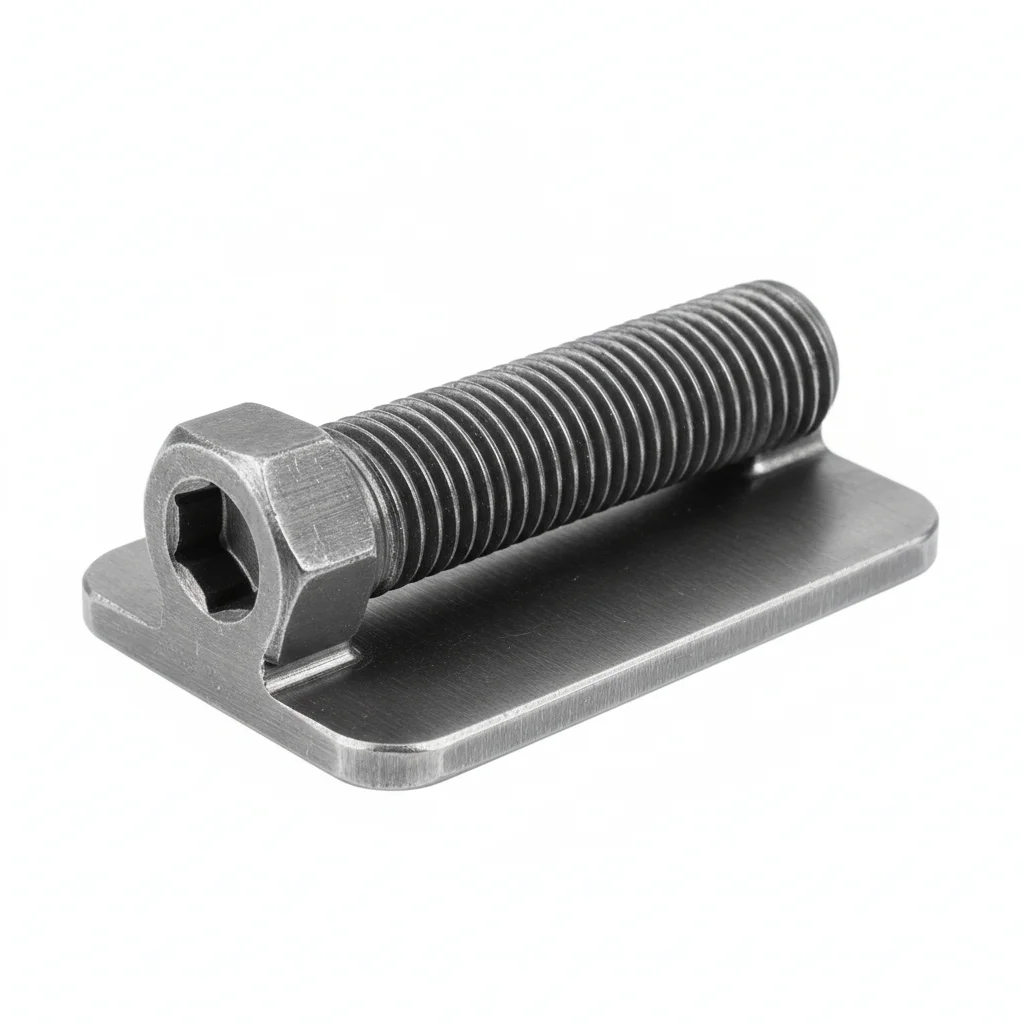
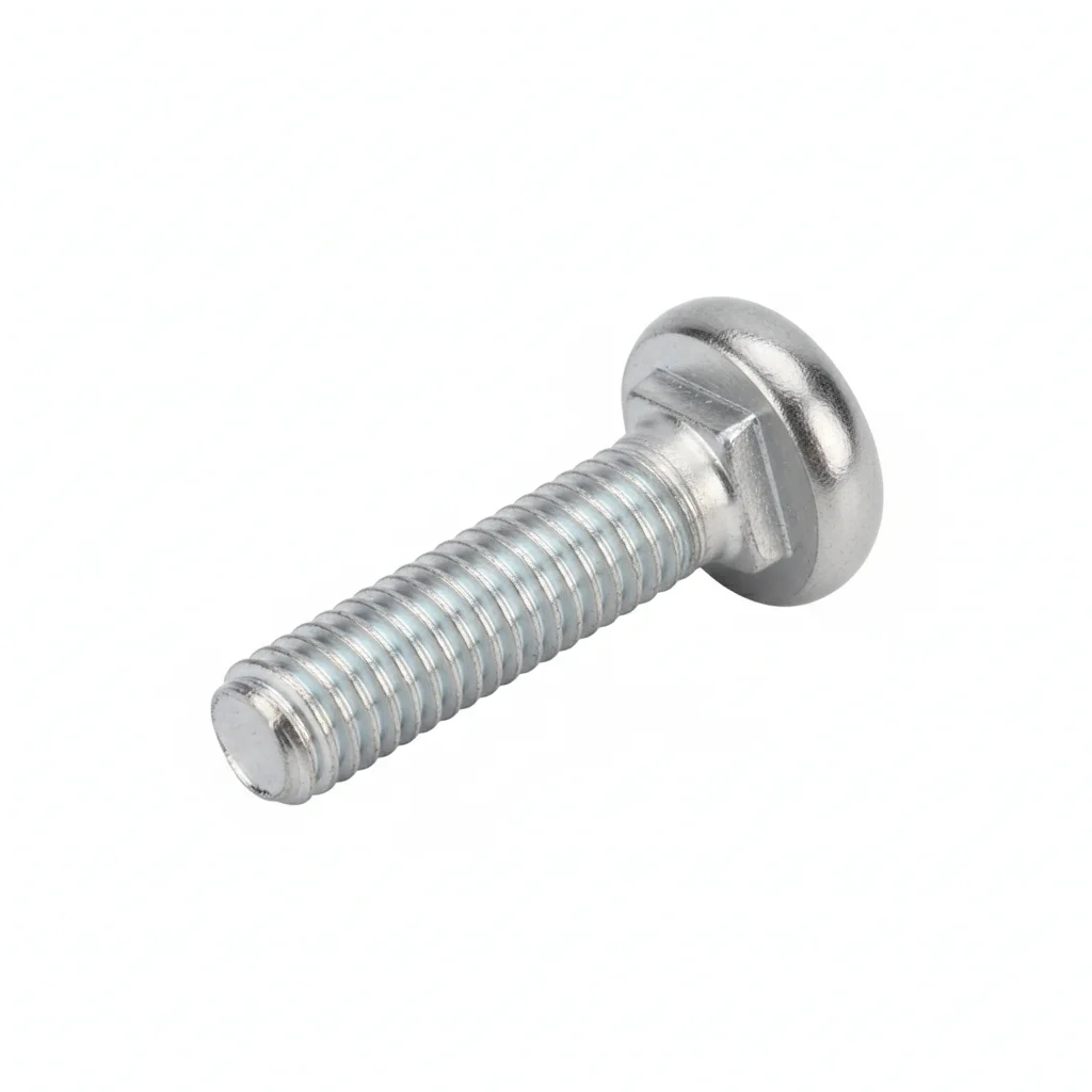
| Rail Clamp Bolt | Fishplate Bolt | |
|---|---|---|
| SPEC | M20-M24 | M20-M24 |
| MATERIAL | 42CrMo | 42CrMoA |
| GRADE | Grade 10.9 Dacromet | Grade 12.9 |
| FINISH | HDG >=55um per ISO 1461 | HDG >=55um per ISO 1461 |
| CORROSION | C3 (ISO 12944-2) | C3 (ISO 12944-2) |
| TEMP | -20°C to +80°C | -20°C to +80°C |
| WEIGHT | ~0.5 kg/piece | ~0.5 kg/piece |
| MOQ | 100 pcs | 100 pcs |
| PACK | VCI paper + carton | VCI paper + carton |
| STD | ISO 898-1, GB/T 3098.1 | ISO 898-1, GB/T 3098.1 |
| USE | Connection between rail clamp and crane beam | Rail joint fishplate |
PROCEDURE
- Clean the crane beam contact surface and rail clamp base with a wire brush to remove rust and debris, then degrease with a solvent.
- Position the rail clamp over the rail foot, insert the M20-M24 Grade 10.9 bolt with a wedge anti-loosening washer under the nut.
- Hand-tighten all bolts in a crisscross pattern, then use a calibrated torque wrench to tighten to the torque specified in the crane manufacturer's manual.
- After initial tightening, perform a second pass after 24 hours to compensate for seating and relaxation.
- Mark each bolt head and nut with a paint line to indicate proper torque; verify alignment of the rail using a steel ruler against the gauge line.
COMMON ERRORS
| ✕ WRONG | CONSEQUENCE | ✓ CORRECT |
|---|---|---|
| Using Grade 8.8 bolts instead of Grade 10.9 for rail clamp bolts | Lower proof load leads to faster preload loss under pulsed stress, causing rail loosening and gauge change within months. | Specify Grade 10.9 per ISO 898-1, with Dacromet coating for corrosion resistance. |
| Overtightening fishplate bolts beyond specified torque | Over-stress may cause thread stripping or bolt fracture, leading to fishplate failure and rail step. | Tighten to the torque value from the crane manual, using a calibrated wrench, and check with a torque audit. |
MAINTENANCE
Inspect rail clamp bolt torque monthly for the first three months after installation, then quarterly on a 20% sample. Verify rail gauge and joint step with a steel ruler quarterly; deviation >1mm requires bolt adjustment. Check for corrosion on fasteners; if pitting depth exceeds 0.3mm or corrosion covers more than 5% of surface area, replace immediately.
B·Heavy/Extra Heavy Crane
C4 Harsh per ISO 12944-2
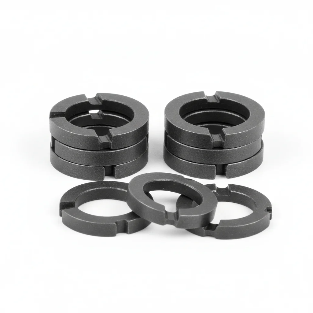
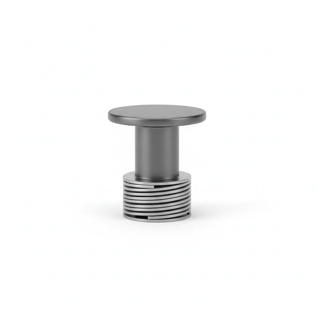
| Wedge Anti-loosening Washer (M20-M24) | Elastic Base Plate Bolt | |
|---|---|---|
| SPEC | M20-M24 | M16 |
| MATERIAL | Carbon Steel Quenched + Dacromet | Alloy Steel + Disc Spring |
| GRADE | Dacromet | Grade 10.9 |
| FINISH | HDG >=55um per ISO 1461 | HDG >=55um per ISO 1461 |
| CORROSION | C3 (ISO 12944-2) | C3 (ISO 12944-2) |
| TEMP | -20°C to +80°C | -20°C to +80°C |
| WEIGHT | ~0.5 kg/piece | ~0.5 kg/piece |
| MOQ | 100 pcs | 100 pcs |
| PACK | VCI paper + carton | VCI paper + carton |
| STD | ISO 898-1, GB/T 3098.1 | ISO 898-1, GB/T 3098.1 |
| USE | Anti-loosening for all rail clamp bolts | Vibration damping + thermal expansion compensation |
PROCEDURE
- Clean the crane beam rail seat with acetone to remove grease, then verify surface roughness Ra <3.2um with a profilometer.
- Apply an anti-corrosion joint compound rated for -20°C to +80°C on the contact faces, and fit PTFE-coated washers under the bolt heads.
- Set the rail clamp and elastic base plate in position, verifying alignment to the rail centerline within 0.5mm; tighten in a cross-pattern sequence to the specified torque.
- After initial tightening, perform a pull-test on 5% of the fasteners to 80% of proof load and replace any that slip.
- Re-torque all bolts after the first week of service to compensate for seating and embedment relaxation.
- Coat exposed threads and washer edges with a weatherproof sealant, and attach a corrosion monitoring coupon near a critical joint.
COMMON ERRORS
| ✕ WRONG | CONSEQUENCE | ✓ CORRECT |
|---|---|---|
| Torquing the M20-M24 rail clamp bolts without the wedge locking washer | The pulsed tensile stress from crane passes will gradually reduce preload, allowing the rail to shift laterally and change the track gauge. | Always install the wedge anti-loosening washer (Dacromet) under the nut for every M20-M24 rail clamp bolt, and torque to the specified value. |
| Using a standard flat washer instead of a disc spring on the elastic base plate bolt | The disc spring is essential for absorbing vibration and thermal expansion; without it, the bolt can loosen or fatigue prematurely. | Use the alloy steel elastic base plate bolt with its integral disc spring, ensuring the spring is properly seated. |
MAINTENANCE
Inspect the rail clamp bolts and elastic base plate bolts at each overhaul window or every 6 months, whichever comes first. Re-torque any fastener that has lost more than 20% of its specified torque. Replace fasteners showing corrosion over 5% of the surface or pitting deeper than 0.3mm. Every 3 years, disassemble and inspect a 20% sample of the fasteners; replace all critical fasteners after 5 years of service regardless of apparent condition.
Plan C · Coastal/Seismic Reinforced Type
C5-M Extreme per ISO 12944-2
| Wedge Anti-loosening Washer (M20-M24) | Elastic Base Plate Bolt | |
|---|---|---|
| SPEC | M20-M24 | M16 |
| MATERIAL | Carbon Steel Quenched + Dacromet | Alloy Steel + Disc Spring |
| GRADE | Dacromet | Grade 10.9 |
| FINISH | HDG >=55um per ISO 1461 | HDG >=55um per ISO 1461 |
| CORROSION | C3 (ISO 12944-2) | C3 (ISO 12944-2) |
| TEMP | -20°C to +80°C | -20°C to +80°C |
| WEIGHT | ~0.5 kg/piece | ~0.5 kg/piece |
| MOQ | 100 pcs | 100 pcs |
| PACK | VCI paper + carton | VCI paper + carton |
| STD | ISO 898-1, GB/T 3098.1 | ISO 898-1, GB/T 3098.1 |
| USE | Extreme conditions / Highest protection | Extreme conditions / Highest protection |
PROCEDURE
- Degrease the rail seat and fastener contact surfaces with MEK solvent, then verify surface roughness Ra <1.6um.
- Apply a marine-grade anti-corrosion compound rated for -50°C to +200°C to all threads and contact faces.
- Position the rail clamp with wedge locking washers and the elastic base plate bolt; use a hydraulic tensioner to reach the target preload for M20-M24 and M16 fasteners.
- Verify the chemical composition of 10% of the fasteners using PMI (Positive Material Identification) and record results for the compliance audit.
- Perform dye penetrant testing on 10% of the installed fasteners to detect surface cracks; replace any that show indications.
- Seal all exposed fastener heads and edges with a protective sealant, then install permanent condition monitoring instrumentation on the rail clamps.
COMMON ERRORS
| ✕ WRONG | CONSEQUENCE | ✓ CORRECT |
|---|---|---|
| Substituting 304 stainless steel wedge washers with carbon steel Dacromet washers in a C5 coastal environment | The carbon steel washers will corrode rapidly despite the Dacromet coating, leading to loss of locking action and potential rail loosening. | For C5-M coastal/seismic applications, use the full Dacromet + 304 stainless steel wedge locking washer set as specified. |
| Skipping the dye penetrant inspection on the elastic base plate bolts after installation | Micro-cracks from the high preload and vibration could go undetected, leading to sudden bolt failure during seismic events. | Perform dye penetrant testing on a 10% sample of the elastic base plate bolts as part of the installation verification. |
MAINTENANCE
Inspect all fasteners at each overhaul window or every 6 months, whichever is sooner, with special attention to the wedge locking washers and elastic base plate bolts. Re-torque any fastener that has lost more than 20% of its specified preload. Replace fasteners with corrosion covering more than 5% of the surface or pitting deeper than 0.3mm. Every 3 years, conduct a full disassembly inspection on a 20% sample; replace all critical fasteners after 5 years of service regardless of apparent condition.
Complete Kit BOM: Rail Clamp · Fishplate · Buffer Stop
Every crane rail fastening kit is itemized on the drawing before production, and the BOM can be released to the client for review, line by line per project.
| Item | Specification | Material | Grade | Finish | Standard basis |
|---|---|---|---|---|---|
| Rail clamp bolt | M20–M24 | 42CrMo | Grade 10.9 Dacromet | HDG ≥55µm per ISO 1461 | ISO 898-1, GB/T 3098.1 |
| Rail joint fishplate bolt | M16 (heavy/extra heavy); M20–M24 (standard) | 42CrMoA | Grade 12.9 | HDG ≥55µm per ISO 1461 | ISO 898-1, GB/T 3098.1 |
| Wedge locking washer | M20–M24 | Carbon steel, quenched + Dacromet | — | HDG ≥55µm per ISO 1461 | ISO 898-1, GB/T 3098.1 |
| Buffer stop set | Per crane tonnage and rail end | Per drawing | Per drawing | Per drawing | Per project |
High-strength bolting assemblies follow GB/T 1231 (steel-structure high-strength hexagon bolt/nut/washer assemblies) for mechanical properties; batch numbers are mapped to each shipment so the MTC, spectrographic analysis report and neutral salt spray test report correspond one-to-one with the physical batch.
Installation technical conditions follow GB/T 32076.10 (high-strength bolted connections — Part 10: installation technical conditions).
SUPPLIER CAPABILITY
Quality, Delivery & Customization
Quality Control
- ✓MTC material certificates with every batch
- ✓Key parts sampled for hardness/salt spray/torque coefficient
- ✓100% inspection or AQL sampling before shipment
Delivery
- ✓Standard parts made to order: 7-15 days
- ✓Custom parts: 25-45 days
- ✓FOB/CIF/DDP supported
Customization
- ✓Drawing review and material matching
- ✓Non-standard sizes/heads/threads
- ✓Small-batch prototyping supported
Certification
- ✓Material certificates (MTC)
- ✓Spectrographic analysis reports
- ✓Salt spray test reports (on request)
MOQ: No MOQ for standard parts; custom parts assessed by process complexity
FAQ
FAQ
RELATED READING
Keep Reading & Next Step
BEYOND TECHNICAL SPECS
Finding the right factory, controlling quality, delivering on time — that's the real challenge. We cover fasteners, rubber, plastics, industrial textiles. One team, end to end.
SEE CAPABILITIES →