Anchor Bolt Failure Risks: Shift and Creep
Anchor bolts fix steel columns to foundations, bearing shear, bending, and uplift. Shift >5mm during pour requires flame cutting holes, reducing load capacity by 20-30%. Chemical anchors creep under sustained tension, losing 20-30% force after 3-5 years. Use positioning templates (8-10mm CNC-drilled) and undercut mechanical anchors for critical joints
FIELD-SPECIFIC INSIGHT
Anchor Bolt Failure Chain: What to Check Before Pouring and After Installation
Two distinct failure modes affect anchor bolt reliability: shift during concrete placement and creep relaxation in chemical anchors. Each requires different prevention and inspection strategies
WHAT TO CHECK
- 1Anchor bolt shift >5mm during pour → steel column base plate holes misalign → on-site flame cutting reduces load capacity by 20-30%
- 2Positioning template (8-10mm thick CNC-drilled steel plate) controls shift to ≤2mm; re-measure within 3 days after pouring and correct before concrete initial set if >5mm
- 3Chemical anchors (epoxy) creep under sustained tensile stress → anchoring force drops 20-30% after 3-5 years → avoid for long-term tension joints like crane beams
- 4Undercut mechanical anchors (seismic C1/C2 certified) provide immediate mechanical interlock, no creep risk, suitable for post-installed critical connections
- 5Anchor bolt projection must be ≥ base plate thickness + double nut + washer + 3-5 threads; foundation elevation errors cause insufficient projection → welding extension rods alters bolt properties
| Check | Why it matters | What to specify |
|---|---|---|
| Embedment shift tolerance | Shift >5mm requires flame cutting holes, reducing load capacity by 20-30% | Positioning template (8-10mm thick) to control shift ≤2mm; re-measure within 3 days |
| Chemical anchor creep under sustained load | Epoxy creep reduces anchoring force 20-30% after 3-5 years | Use undercut mechanical anchors for long-term tension joints; chemical anchors only for static loads |
| Anchor bolt projection above foundation | Insufficient projection prevents nut installation → on-site welding weakens joint | Projection ≥ base plate thickness + double nut + washer + 3-5 threads; GB 50205 deviation ≤ ±5mm |
| Material and coating for corrosion | Corrosion reduces bolt section and load capacity | 304/316L stainless for aggressive environments |
All torque and tension values must be verified per project specifications; maintenance intervals depend on actual operating conditions
Evidence level: source-page-only
RISK AUDIT // ENGINEERING DIAGNOSIS
Procurement Pitfall Guide
"Field failures that erode joint integrity: shift during pour and creep under load."
QC-AUDIT // REV.5
SCALE 1:1 · 03 ITEMS
RISK-01
Anchor bolts shift during concrete pouring
Corrective Measures
RISK-02
Creep relaxation of chemical anchors under long-term load
Corrective Measures
RISK-03
Insufficient anchor bolt projection prevents steel column installation
Corrective Measures
INDUSTRY TECH REFERENCE
Anchor Embedment Deviation: Check Items, Allowances, and the Cost of Overrun
Whether a column seats cleanly and the joint carries load as designed is decided by deviation control before the pour. These three acceptance lines come from GB 50205-2020 §10.2 — apply them at incoming inspection and re-check before pouring.
| Check item | Acceptance line | What overrun costs |
|---|---|---|
| Center offset | Allowable deviation 2.0 mm | Base-plate holes no longer line up → field reaming or flame cutting weakens the joint |
| Exposed length | Negative deviation not allowed | Nut cannot fully engage the threads → under-preload and loosening risk |
| Thread length | Negative deviation not allowed | Too few threads in engagement → threads strip under heavy load |
No order-of-magnitude estimates are used in this slot.
INDUSTRY TECH REFERENCE
Choosing the Anchor Path: J-Bolt Embed, Post-Drilled, or Sleeve-and-Grout
Settle the anchoring path before the pour: embedment, post-drilling, and cast-in sleeves carry three different cost ledgers, and a late switch only shows its price once the site crew arrives.
Pre-embedded J-type hook bolts cost the least, with one weak point — positioning accuracy: if the bolt group drifts, the column base plate will not line up, so a positioning template locks the group into one rigid unit before pouring and holds the center offset within the 2.0 mm allowance. Post-drilled anchoring (chemical or mechanical anchors) positions most accurately, at the cost of drilling: the bit can strike rebar, forcing a shift and a re-drill. A cast-in sleeve with post-grouting sits in the middle on cost, with the weak point in the epoxy grout fill — an epoxy fill done poorly leaves a defect inside the foundation. The three paths fail at different moments: embedment fails at pour time and the deviation is irreversible, post-anchoring fails at drilling time (rebar strikes, damaged hole walls), and sleeve-and-grout fails at grouting time (voids, cracks). Pick the path with the foundation type and fix it before the pour — do not leave it for the field.
No order-of-magnitude estimates are used in this slot.
INDUSTRY TECH REFERENCE
The Corrosion Chain in a Cracked Grout Layer: Shrinkage to Anchor Pullout
When secondary grouting uses plain cement mortar, shrinkage cracks become a corrosion path. Every step of the chain can be checked on site — do not wait for wind or a quake to pull a corroded anchor out.
- 1Secondary grouting with ordinary cement mortar → shrinkage cracks after hardening (the GB/T 50448 system requires cement-based grout for secondary grouting)
- 2Cracks reach the anchor bolt surface; moisture travels down them
- 3The anchor corrodes, its section shrinks, and load capacity drops
- 4Under wind or seismic extremes the corroded anchor pulls out of the foundation and the column loses stability
- 5Interception: treat the grout layer as a controlled item — pick the grout per GB/T 50448 and verify no through-cracks; for exposed column bases and equipment footings, allow corrosion margin for the environment (GB 50017 §12.7.5 commentary)
No order-of-magnitude estimates are used in this slot.
PLAN COMPARISON
Three-Plan Core Parameter Comparison
Compare row by row. Click column headers to jump to plan details.
| A · A · Standard Column Base | B · B · Heavy-Duty / Post-Installed Anchoring | C · Plan C · Coastal / Seismic Reinforced | |
|---|---|---|---|
| 1. J-BOLT ANCHOR | |||
| SPEC | M24-M48 | M16-M30 | M16-M30 |
| MATERIAL | Q345B Hot-Dip Galvanized | 304 Stainless Steel | 316L Stainless Steel |
| GRADE | GB/T 799 | Seismic C1/C2 Certified | Seismic C1/C2 Certified |
| FINISH | HDG, >=55um per ISO 1461 | HDG, >=55um per ISO 1461 | HDG, >=55um per ISO 1461 |
| 2. TEMPLATE PLATE | |||
| SPEC | 8-10mm thick | M12-M24 | M12-M24 |
| MATERIAL | Q235B | Carbon Steel Galvanized + Epoxy | Carbon Steel Galvanized + Epoxy |
| FINISH | HDG, >=55um per ISO 1461 | HDG, >=55um per ISO 1461 | HDG, >=55um per ISO 1461 |
A · Standard Column Base
C3 Indoor, -10-40C per ISO 12944-2
REF: ISO 898-1, GB/T 3098.1
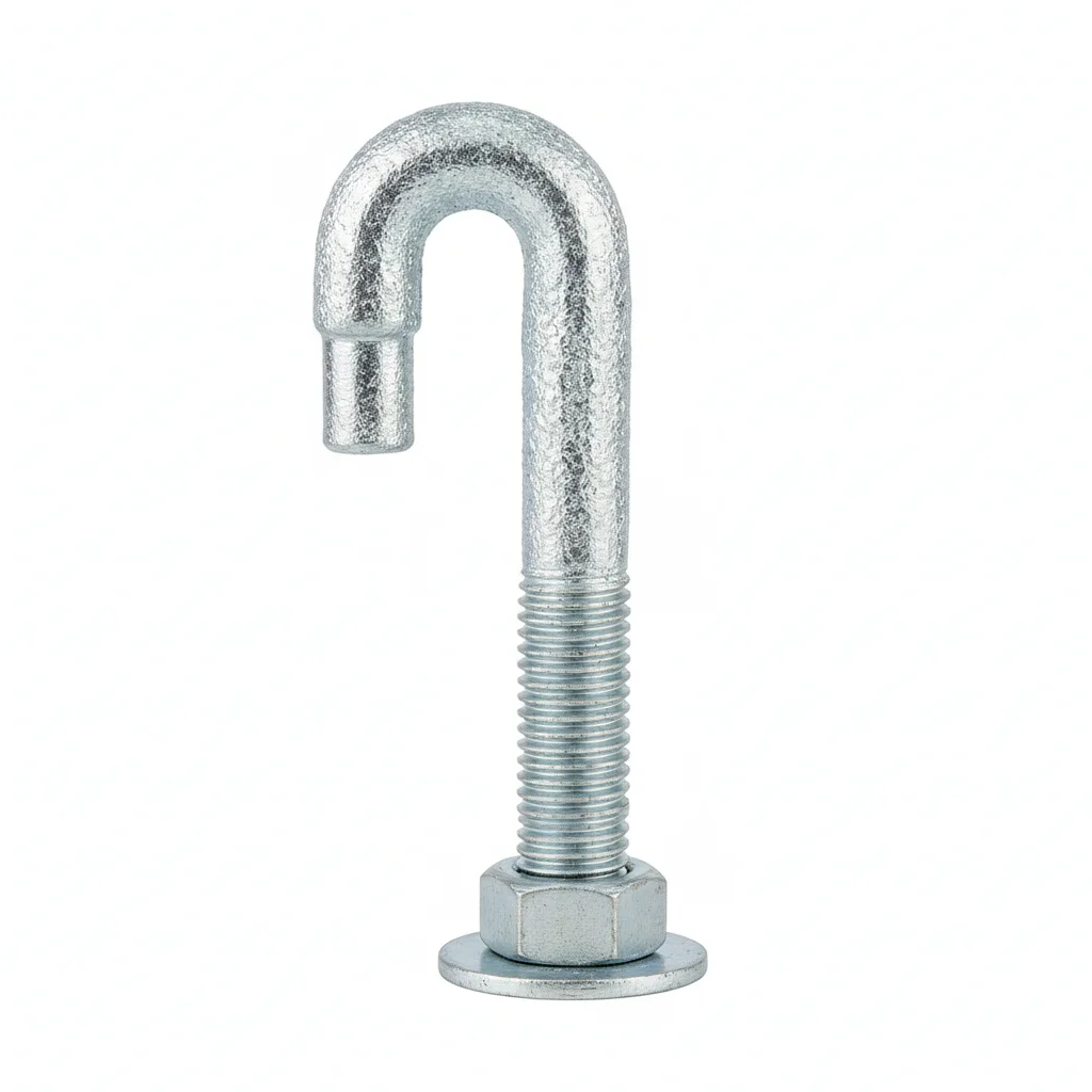
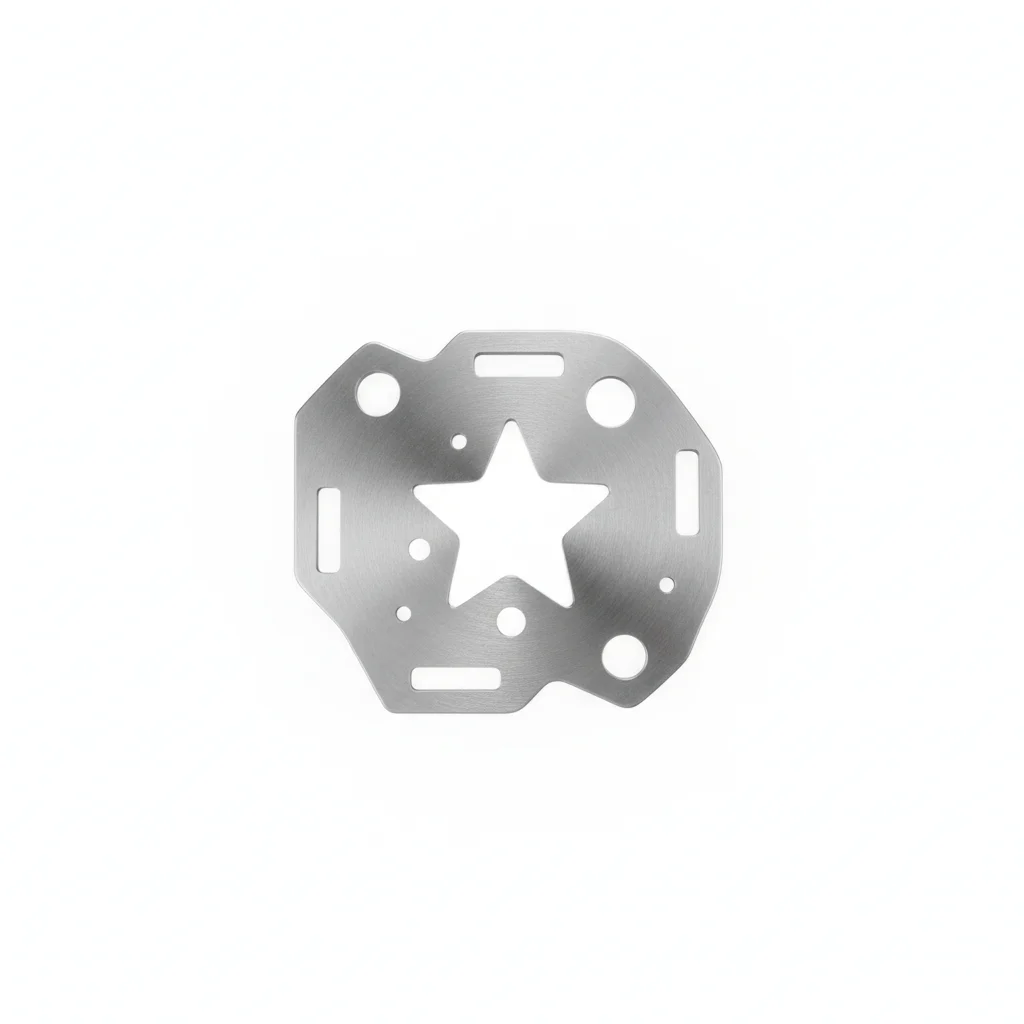
| J-Bolt Anchor | Template Plate | |
|---|---|---|
| SPEC | M24-M48 | 8-10mm thick |
| MATERIAL | Q345B Hot-Dip Galvanized | Q235B |
| GRADE | GB/T 799 | — |
| FINISH | HDG, >=55um per ISO 1461 | HDG, >=55um per ISO 1461 |
| CORROSION | C3 (ISO 12944-2) | C3 (ISO 12944-2) |
| TEMP | -20°C to +80°C | -20°C to +80°C |
| WEIGHT | ~0.5 kg/piece | ~0.5 kg/piece |
| MOQ | 100 pcs | 100 pcs |
| PACK | VCI paper + carton | VCI paper + carton |
| STD | ISO 898-1, GB/T 3098.1 | ISO 898-1, GB/T 3098.1 |
| USE | Steel column base embedment | Anchor bolt embedment precision control |
PROCEDURE
- Assemble the J-Bolt group onto the 8-10mm CNC-drilled positioning template, aligning bolts to the template holes; secure with nuts to create a rigid unit.
- Weld the positioning template to the foundation rebar cage, ensuring the template is level and at the correct elevation; verify bolt spacing and projection against the steel column base plate hole pattern.
- During concrete pouring, monitor bolt displacement in real time; use the template to hold shift within 2mm while vibration proceeds.
- Within 3 days after pouring, re-measure bolt centers and projection; if deviation exceeds 5mm, correct before the concrete initial set.
- After concrete cures, remove the template and check that the exposed threads are clean; install the steel column base plate, then tighten nuts to the specified torque per ISO 898-1.
COMMON ERRORS
| ✕ WRONG | CONSEQUENCE | ✓ CORRECT |
|---|---|---|
| Omitting the positioning template and relying on manual placement of anchor bolts during pour. | Bolts shift 3-10mm due to concrete pressure; shift >5mm forces flame cutting of base plate holes, cutting load capacity by 20-30%. | Use a CNC-drilled positioning template (8-10mm thick) to fix the bolt group as a unit; weld template to rebar to lock alignment. |
| Welding extension rods onto anchor bolts that project too short above the foundation. | Welding heat-affected zone alters bolt mechanical properties, causing brittle fracture risk under load. | If projection is >10mm short, use rebar planting (chemical or mechanical) to extend; never weld extensions. |
MAINTENANCE
Seasonally inspect anchor bolt exposed threads and base plate for corrosion (HDG ≥55um per ISO 1461) and verify nut tightness; at each overhaul window, check for signs of shift or loosening. For chemical anchors in static load applications, apply a creep reduction factor of 0.6 to design values and perform non-destructive pull-out tests every 3 years.
B · Heavy-Duty / Post-Installed Anchoring
C3 Indoor, -10-40C per ISO 12944-2
REF: ISO 898-1, GB/T 3098.1
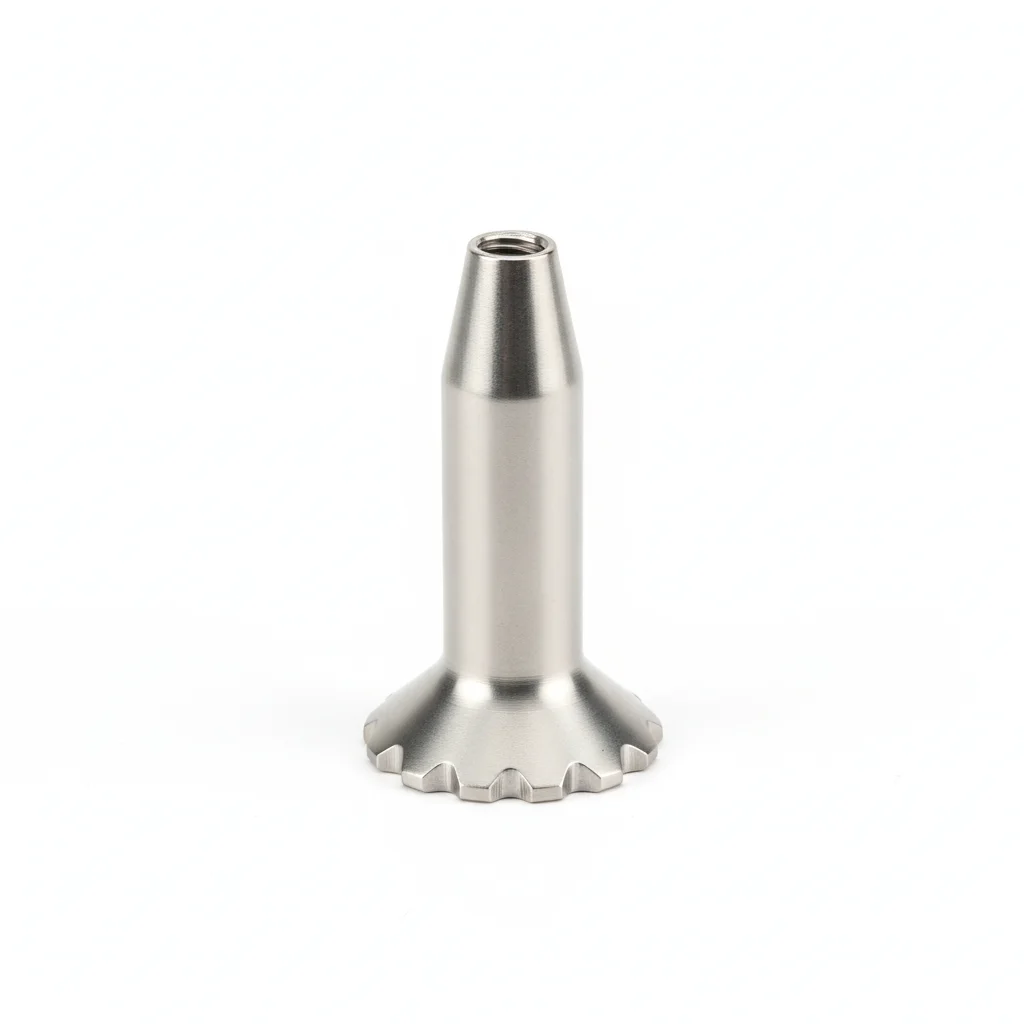
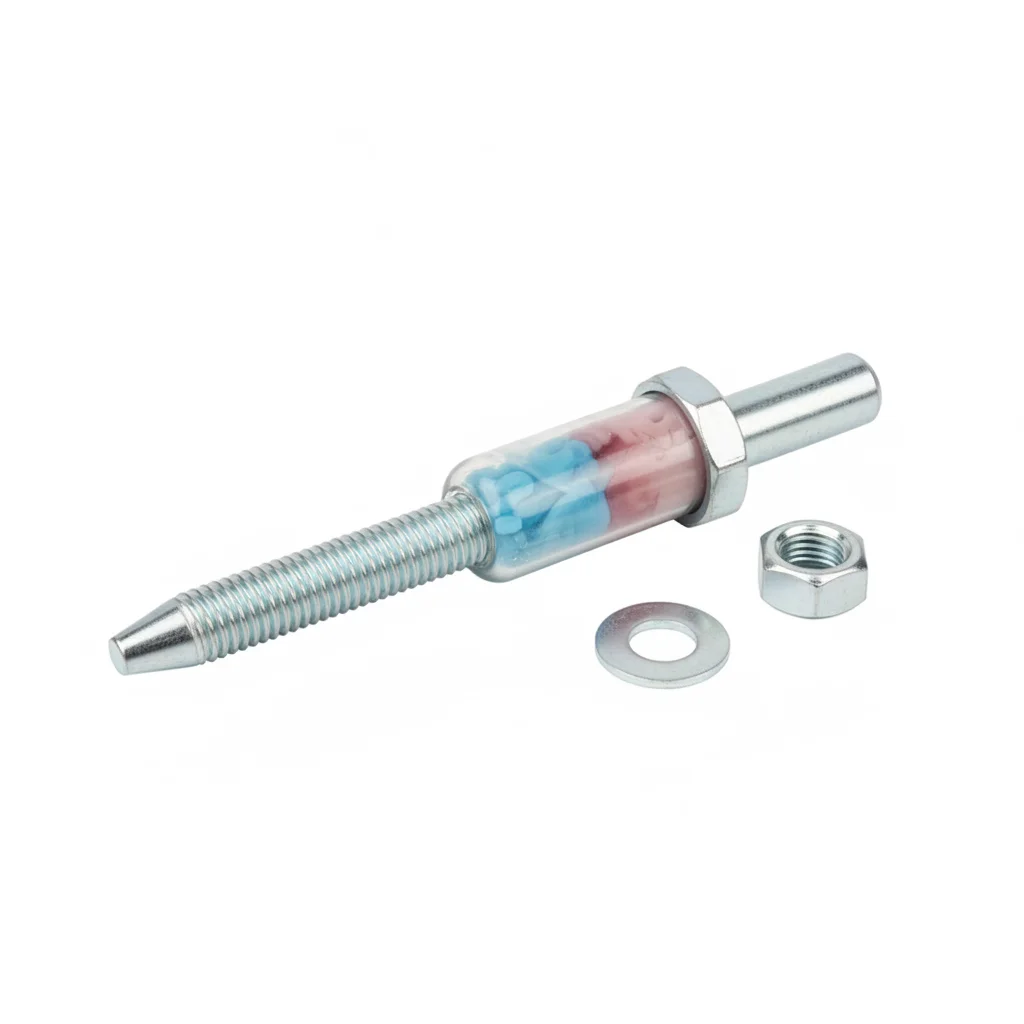
| Undercut Mechanical Anchor | Chemical Anchor | |
|---|---|---|
| SPEC | M16-M30 | M12-M24 |
| MATERIAL | 304 Stainless Steel | Carbon Steel Galvanized + Epoxy |
| GRADE | Seismic C1/C2 Certified | — |
| FINISH | HDG, >=55um per ISO 1461 | HDG, >=55um per ISO 1461 |
| CORROSION | C3 (ISO 12944-2) | C3 (ISO 12944-2) |
| TEMP | -20°C to +80°C | -20°C to +80°C |
| WEIGHT | ~0.5 kg/piece | ~0.5 kg/piece |
| MOQ | 100 pcs | 100 pcs |
| PACK | VCI paper + carton | VCI paper + carton |
| STD | ISO 898-1, GB/T 3098.1 | ISO 898-1, GB/T 3098.1 |
| USE | Crane girder / Post-installed anchoring | Static load post-installed anchoring |
PROCEDURE
- Drill holes in concrete using a hammer drill with a carbide bit to the specified depth and diameter for the undercut anchor, ensuring the hole is perpendicular to the surface.
- Clean the drilled hole of dust and debris using a wire brush and vacuum, then verify the hole depth with a depth gauge.
- Insert the undercut mechanical anchor into the hole and expand it by tightening the nut to the manufacturer's recommended torque, achieving mechanical interlock.
- For chemical anchors, inject the epoxy adhesive into the cleaned hole, then insert the anchor rod with a slow twisting motion to ensure full coating, and allow to cure per the product's specified time.
- After installation, perform a pull-out test on a sample of anchors to verify holding strength, using a calibrated tension tester.
- Position the steel column base plate over the anchors and secure with washers and nuts, torquing to the specified value in a cross-pattern.
COMMON ERRORS
| ✕ WRONG | CONSEQUENCE | ✓ CORRECT |
|---|---|---|
| Using a chemical anchor for a crane girder connection without considering creep | Epoxy adhesive creeps under sustained tensile load, reducing anchoring force by 20-30% after 3-5 years, risking failure of the crane girder connection. | For long-term tension joints like crane girders, use undercut mechanical anchors that provide immediate mechanical interlock and no creep. |
| Oversizing the drilled hole for the undercut anchor | The anchor may not expand properly, leading to reduced pull-out capacity and potential failure under load. | Drill the hole to the exact diameter specified for the anchor size, and verify with a gauge before insertion. |
MAINTENANCE
At each overhaul window, inspect anchor bolts for signs of corrosion, loosening, or displacement. For chemical anchors, perform non-destructive pull-out tests every 3 years to detect creep relaxation. Re-torque any anchor that shows loosening to the specified torque value.
Plan C · Coastal / Seismic Reinforced
C4 Harsh C5 Corrosion / Seismic Fortification Intensity 8
REF: ISO 898-1, GB/T 3098.1
| Undercut Mechanical Anchor | Chemical Anchor | |
|---|---|---|
| SPEC | M16-M30 | M12-M24 |
| MATERIAL | 316L Stainless Steel | Carbon Steel Galvanized + Epoxy |
| GRADE | Seismic C1/C2 Certified | — |
| FINISH | HDG, >=55um per ISO 1461 | HDG, >=55um per ISO 1461 |
| CORROSION | C3 (ISO 12944-2) | C3 (ISO 12944-2) |
| TEMP | -20°C to +80°C | -20°C to +80°C |
| WEIGHT | ~0.5 kg/piece | ~0.5 kg/piece |
| MOQ | 100 pcs | 100 pcs |
| PACK | VCI paper + carton | VCI paper + carton |
| STD | ISO 898-1, GB/T 3098.1 | ISO 898-1, GB/T 3098.1 |
| USE | Extreme conditions / Maximum protection | Extreme conditions / Maximum protection |
PROCEDURE
- Verify 316L stainless steel material grade via PMI testing on all anchors before installation to ensure corrosion resistance in coastal environments.
- Drill holes using a diamond core drill to minimize micro-cracking in concrete, then clean thoroughly with a brush and vacuum.
- For undercut anchors, set the undercutting tool to the specified depth and rotate to create the undercut, then insert the anchor and expand by torquing to the specified value.
- For chemical anchors in seismic zones, use a hybrid system: first set a mechanical undercut anchor for immediate load capacity, then inject epoxy for additional bond strength.
- Apply Dacromet coating touch-up on any scratched areas of the anchor or base plate to maintain corrosion protection.
- Secure the column base with wedge lock washers under the nuts, and torque to the specified value using a calibrated wrench.
COMMON ERRORS
| ✕ WRONG | CONSEQUENCE | ✓ CORRECT |
|---|---|---|
| Using standard carbon steel anchors in a coastal environment without adequate protection | Corrosion can reduce the anchor cross-section, leading to premature failure under load or seismic events. | Use 316L stainless steel anchors with Dacromet coating for maximum corrosion resistance in C5 environments. |
| Insufficient embedment depth for seismic loading | Anchors may pull out during seismic activity, causing structural failure. | Ensure anchors are embedded to the depth specified for seismic fortification intensity 8, and use seismic-certified anchors with C1/C2 rating. |
MAINTENANCE
Inspect anchors annually for corrosion, especially in coastal splash zones, and replace any showing >5% surface corrosion. At each overhaul window, perform non-destructive pull-out tests on a sample of anchors to verify capacity. Re-torque any loosened anchors to the specified torque value.
SELECTION GUIDE
Choose Your Anchor Strategy
| Operating condition | Recommended option | Key basis |
|---|---|---|
| Embedded anchoring — standard column base (C3 indoor, -10 to 40°C per ISO 12944-2) | Option A: hook bolt + positioning template — J-bolt anchor (M24-M48, Q345B, hot-dip galvanized, per GB/T 799) + template plate (8-10mm thick, Q235B) to fix each bolt group as a unit | GB/T 799 anchor bolts; C3 indoor, -10 to 40°C per ISO 12944-2 |
| Post-installed anchoring (crane girder / heavy-duty, long-term tension joints) | Option B: mechanical anchor preferred — undercut mechanical anchor (M16-M30, 304 stainless steel, seismic C1/C2 certified, pure mechanical interlock, no creep); chemical anchor (M12-M24, carbon steel galvanized + epoxy) for static loads only | ETAG 001 metal anchors; seismic C1/C2 certified |
| Coastal / seismic reinforced — C5 corrosion / seismic fortification intensity 8 | Plan C · Coastal/Seismic Reinforced: full-range Dacromet + 304 stainless steel + wedge lock washer for anti-loosening — undercut mechanical anchor (M16-M30, 316L stainless steel, seismic C1/C2 certified) + chemical anchor (M12-M24, carbon steel galvanized + epoxy) | ISO 12944-2 C4 harsh / C5 corrosion; GB 50017 standard for design of steel structures |
REFERENCED STANDARDS
References
SUPPLIER CAPABILITY
Quality, Delivery & Customization
Quality Control
- ✓MTC material certificates with every batch
- ✓Key parts sampled for hardness/salt spray/torque coefficient
- ✓100% inspection or AQL sampling before shipment
Delivery
- ✓Standard parts made to order: 7-15 days
- ✓Custom parts: 25-45 days
- ✓FOB/CIF/DDP supported
Customization
- ✓Drawing review and material matching
- ✓Non-standard sizes/heads/threads
- ✓Small-batch prototyping supported
Certification
- ✓Material certificates (MTC)
- ✓Spectrographic analysis reports
- ✓Salt spray test reports (on request)
MOQ: No MOQ for standard parts; custom parts assessed by process complexity
FAQ
FAQ
RELATED READING
Keep Reading & Next Step
NEXT: SELECTION & RFQ
Bracing & Anti-Corrosion HardwareFollow this page's selection path to the same-scenario RFQ page.
RELATED TOPIC
High-Strength BoltsRELATED TOPIC
Purlin ConnectorsBEYOND TECHNICAL SPECS
Finding the right factory, controlling quality, delivering on time — that's the real challenge. We cover fasteners, rubber, plastics, industrial textiles. One team, end to end.
SEE CAPABILITIES →