Coupling Bolts: Fatigue, Preload Loss & Fire Risk
A diesel engine flywheel and torque converter are connected by dozens of flange bolts — if any one bolt fails due to fatigue → the broken bolt fragment is flung out by the high-speed rotating flywheel → penetrates the converter housing → hydraulic oil sprays onto the hot exhaust pipe → fire. The stainless steel diaphragm of a diaphragm coupling transmits hundreds of kW of torque through bolts — once the bolt preload decays → the diaphragm repeatedly bends under alternating torque → metal fatigue → the diaphragm tears at the bolt holes → the coupling disintegrates instantly.
RISK AUDIT // ENGINEERING DIAGNOSIS
Procurement Pitfall Guide
"When torque pulses meet thermal cycles, bolt failures ignite more than downtime."
QC-AUDIT // REV.5
SCALE 1:1 · 03 ITEMS
RISK-01
Flywheel Bolt Fatigue Fracture Under Torque Pulses
Corrective Measures
RISK-02
Preload Relaxation Under High-Temperature Thermal Cycling
Corrective Measures
RISK-03
Galvanic Corrosion Failure in Marine Corrosive Environments
Corrective Measures
FIELD-SPECIFIC INSIGHT
Critical Checks for Coupling Bolt Reliability
The most overlooked engineering difference in heavy equipment coupling bolts is the combined effect of torque pulse frequency, thermal cycling preload loss, and galvanic corrosion — each can independently cause failure, but together they accelerate fatigue beyond standard design life.
WHAT TO CHECK
- 1Flywheel bolts experience alternating shear stress at 1.5x engine speed; after 10^8 cycles (~5000h), 12.9 grade fine thread bolts may fracture suddenly → fire risk. Specify full-set synchronous replacement every 3000h with magnetic particle testing.
- 2Thermal cycling from -40°C to 200°C causes preload drop up to 40% after 1000 cycles → connection stiffness decreases → oil leakage. Use disc spring washers (60Si2Mn, Dacromet) for elastic compensation.
- 3In marine environments, carbon steel fasteners on stainless steel substrate form galvanic couple with corrosion rate 0.2mm/year → fatigue life reduced to 30%. Specify HDG >=55µm per ISO 1461 and inspect pitting depth >0.3mm.
- 4For large mining equipment, safety wire (304 or 316L) provides secondary locking against bolt loosening under extreme vibration. Use Plan C with 42CrMoA quenched + hard chrome plating for -40°C to +80°C.
| Check | Why it matters | What to specify |
|---|---|---|
| Torque pulse frequency vs bolt fatigue life | Each power stroke generates alternating shear stress; after 10^8 cycles, 12.9 grade bolts may fracture suddenly | Disassembly inspection + magnetic particle testing + full-set synchronous replacement every 3000h |
| Preload relaxation under thermal cycling | After 1000 cycles from -40°C to 200°C, preload drops 40% → connection stiffness decreases → oil leakage | Use disc spring washers (60Si2Mn, Dacromet) and re-torque if below 80% specified torque |
| Galvanic corrosion in marine environment | Carbon steel on stainless steel: corrosion rate 0.2mm/year → fatigue life reduced to 30% | HDG >=55µm per ISO 1461; replace if corrosion >5% surface area or pitting depth >0.3mm |
| Bolt locking under extreme vibration | Large mining equipment vibration can loosen bolts → coupling disassembly | Safety wire (304 or 316L) for secondary locking; use Plan C for -40°C to +80°C |
All data from page content. For specific torque values and inspection intervals, refer to equipment OEM manual.
Evidence level: source-page-only
INDUSTRY TECH REFERENCE
Three Assembly Sins: How Coupling High-Strength Bolts Climb from Micro-Loosening to Whole-Group Fracture
Sudden fracture of flywheel coupling bolts does not begin in service — it begins at the assembly bench. Walk the recorded failure chain: how three assembly defects bury the preload, and how that preload walks the whole bolt group into fatigue.
- 1Three assembly defects plant the mine first: uneven anaerobic adhesive / uncleaned thread holes / torque short of the drawing value — any one of them makes the preload unreal from the start (the attribution stated in a journal failure analysis)
- 2Micro-loosening in service: the joint is sheared radially under alternating loads such as ignition/transmission torque pulses; the bolt switches from tension to shear-plus-bending, and the thread root becomes the origin of fatigue cracks
- 3Unstable crack growth: the 31 bolts carrying fatigue traces fail one by one, and the remaining 5 snap under instantaneous overload — in the record, all 36 M22×75, grade-10.9, 40Cr bolts had broken after 1128 hours
- 4The consequence chain: the connection fails instantly — at once a stoppage event and a safety event, a loss to the OEM and the user alike
- 5The interception: assembly quality is the life-or-death point — clean thread holes, even adhesive, torque to the drawing (torque-plus-angle; see the acceptance table); passing chemistry, hardness and metallography does not immunize against fatigue — the fracture itself is the fingerprint of assembly quality
The ignition/transmission torque pulse is a qualitative description of the coupling duty, carrying no figures. No order-of-magnitude estimates are used in this slot.
INDUSTRY TECH REFERENCE
Read the Fracture First: Fatigue or Overload — the Extraction Method Tells You
Flywheel bolts give no warning before they break, and walk-around inspection cannot see it coming — the fracture is the only eyewitness. How to read it? The extraction method is enough.
When a coupling high-strength bolt group fails in batches, the first move is not returning the bolts — it is reading the fracture. The record: after all 36 bolts broke, 16 returned bolts were inspected — 6 fully fatigue-induced, 4 half-fatigue, the rest also carrying fatigue traces, with only 5 of the whole set failing in instantaneous overload; fatigue-fractured bolts could be pulled from the thread holes by hand (their mating threads were worn smooth), while overload-fractured ones needed hammer and chisel — the fracture morphology is the fingerprint of assembly quality. What is even more counter-intuitive: this batch passed chemistry, hardness and metallography against GB/T 3077 and GB/T 3098.1, manufacturing defects were ruled out, and the fault lay in assembly. So when you receive fracture data from a supplier, ask three questions first: does the assembly record exist? was the anaerobic adhesive applied evenly? was the torque taken to the drawing value? Those three questions carry more audit value than a return — they redirect the blame from "bolt quality" to "assembly practice", and assembly is the one link the field can actually change.
No order-of-magnitude estimates are used in this slot.
INDUSTRY TECH REFERENCE
Acceptance Check for Coupling High-Strength Bolt Groups: What, Per What Baseline, What Goes Wrong
Accept the preload, not the bolt: five checks in assembly order, each with a verifiable baseline and the consequence of skipping it.
| Check item | Correct baseline | Failure consequence (record / mechanism) |
|---|---|---|
| Thread-hole cleaning | Clear residual adhesive and chips before assembly (one of the three assembly defects) | Dirty holes → unreal preload → the start of micro-loosening |
| Anaerobic adhesive application | Apply evenly; a dab or two counts as a defect | Uneven application → poor assembly → micro-loosening |
| Torque execution | Torque to the drawing plus torque-angle method: after the initial torque, turn 1/3 turn further; the initial torque only seats the joint, the +1/3 turn provides the holding force | Torque short of the drawing → insufficient preload → shear-plus-bending → thread-root fatigue (record: all 36 bolts broken at 1128 h, 31 with fatigue traces) |
| Material & grade verification | 40Cr/42CrMo per GB/T 3077-2015; grades 8.8/10.9/12.9 per GB/T 3098.1-2010 (both current) | Passing chemistry/hardness/metallography does not prevent fatigue fracture — with manufacturing defects ruled out, the liability shifts to assembly |
| Re-tightening checkpoint | Inspect and re-tighten as needed after 50-100 hours of operation following new fitment or refit (OEM practice) | Skipped → early loosening goes unnoticed → the micro-loosening → shear → thread-root fatigue chain continues (mechanistic inference) |
GB/T 3077-2015 and GB/T 3098.1-2010 are current standards; the last row ("skipped → micro-loosening → shear → thread-root fatigue chain") is an inference from the failure mechanism, not an independent figure. No order-of-magnitude estimates are used in this slot.
INDUSTRY TECH REFERENCE
Buying Coupling Bolts: The Downtime Ledger, Not the Unit-Price Ledger
Coupling and flywheel bolts are made-to-print high-strength bolt groups with a quoting logic entirely different from standard parts. Until the downtime ledger is worked out, a unit-price difference means nothing.
- Run the downtime ledger first: unplanned downtime averages about $125,000/hour (2023 ABB/Sapio survey of 3,215 maintenance decision-makers, all-industry basis) — a coupling-bolt failure is first a stoppage event, not a parts event
- Know the two magnitudes of stoppage: a minor loose joint fixable on site in 45 minutes, versus a whole-machine-class major overhaul after a high-strength bolt group breaks completely — a flywheel/coupling connection fracture is the latter (reference record: all 36 bolts broke)
- Account per hour, not per piece: the undercarriage can reach ≤20% of the new-machine price and ≤50% of maintenance cost, and leading manufacturers buy by cost per undercarriage hour — the same logic applies to coupling bolts, so supplier quotes become comparable only when converted against whole-machine downtime cost
- Non-standard made-to-print parts are bound to the OEM: coupling high-strength bolts are made-to-drawing parts, and the risk of an alternative part is asymmetric — its failure is a career stain for the user who chose it; however low the quote, pass the assembly and batch gate first
- Put assembly and batch into the contract: fracture morphology equals the fingerprint of assembly quality (record: 31 of 36 with fatigue traces), so acceptance items should cover traceable assembly records and whole-group synchronous scrapping on failure — not unit-price differences
The ≈$125,000/hour is an all-industry statistic for unplanned downtime; the "45-minute field fix" is a single field case, not a general commitment. No order-of-magnitude estimates are used in this slot.
INDUSTRY TECH REFERENCE
Grade & Material Baselines for Flywheel Coupling Bolts: Match These GB Standards
Before an RFQ says "42CrMoA, grade 12.9", line up two numbers: which standard judges the grade, and which judges the material — failure analyses use the same yardstick in hindsight. Navigation only, no clauses reproduced.
The listed standards (GB/T 3098.1-2010, GB/T 3077-2015) are current public national standards, given for procurement navigation with their scope only, without reproducing standard clauses; material/grade compliance can be cross-checked by failure analysis (the case of 40Cr bolts judged conforming to GB/T 3077 and GB/T 3098.1). No order-of-magnitude estimates are used in this slot.
PLAN COMPARISON
Three-Plan Core Parameter Comparison
Compare row by row. Click column headers to jump to plan details.
| A · A · Medium | B · B · Large Mining | C · Plan C · Mining/Extreme Conditions | |
|---|---|---|---|
| 1. FLYWHEEL FLANGE BOLT | |||
| SPEC | M14-M20 Fine Thread | M20-M24 Fine Thread | M20-M24 Fine Thread |
| MATERIAL | 42CrMoA | 42CrMoA | 42CrMoA |
| GRADE | 12.9 Grade | 12.9 Grade | 12.9 Grade |
| FINISH | HDG >=55um per ISO 1461 | HDG >=55um per ISO 1461 | HDG >=55um per ISO 1461 |
| 2. HEAVY-DUTY DISC SPRING WASHER | |||
| SPEC | M14-M20 | φ0.8-1.2mm | φ0.8-1.2mm |
| MATERIAL | 60Si2Mn | 304 | 316L |
| GRADE | Dacromet | — | — |
| FINISH | HDG >=55um per ISO 1461 | HDG >=55um per ISO 1461 | HDG >=55um per ISO 1461 |
SELECTION GUIDE
Select Your Coupling Bolt Plan
| Operating condition | Recommended option | Key basis |
|---|---|---|
| Medium-duty flywheel connection, C3 per ISO 12944-2 (-20°C to +80°C) | Option A · 12.9 + disc spring: flywheel flange bolt M14-M20 fine thread (42CrMoA, 12.9 grade) + heavy-duty disc spring washer M14-M20 (60Si2Mn, Dacromet) | ISO 898-1; VDI 2230 (bolted joint calculation) |
| Large mining equipment flywheel, C4 harsh per ISO 12944-2 | Option B · 12.9 + safety wire: flywheel bolt M20-M24 fine thread (42CrMoA, 12.9 grade) + safety wire φ0.8-1.2mm (304) | ISO 12944-2 C4; AGMA 9002 (coupling installation) |
| Torque pulses from diesel power strokes (alternating shear stress at 1.5× engine speed, thousands of pulses per minute) | Use 12.9 grade fine thread bolts + thread locking adhesive + safety wire (every 2-3 bolts as a group, connected in series with stainless steel wire — if one loosens, the wire holds it and prevents it flying off); tighten strictly in a cross-symmetrical pattern in 3 stages; disassemble and inspect every 3000 operating hours — if any bolt shows cracks (magnetic particle testing) or torque decay >20%, replace the entire set synchronously | ISO 898-1; after 10⁸ cycles (approximately 5000 operating hours) fatigue damage accumulates to a critical value → sudden fracture → fragments flung out by the high-speed flywheel → penetrate the converter housing → hydraulic oil on the hot exhaust pipe → fire |
| High-temperature thermal cycling (-40°C to 200°C) | Use constant preload technology (e.g., disc spring washers) or nickel-based alloys with low thermal expansion coefficients; control preload decay within 5% | After 1000 cycles preload drops by 40% → connection stiffness decreases → oil leakage risk increases |
| Marine corrosive environment (3.5% NaCl salt spray) | Use insulating coatings to isolate dissimilar metals, or select the same corrosion-resistant material (e.g., 316L stainless steel); add a cathodic protection system | Carbon steel fasteners in contact with a stainless steel substrate form a galvanic couple, corrosion rate 0.2mm/year → fatigue life reduced to 30% of the original design |
A · Medium
C3 per ISO 12944-2, -20°C to +80°C
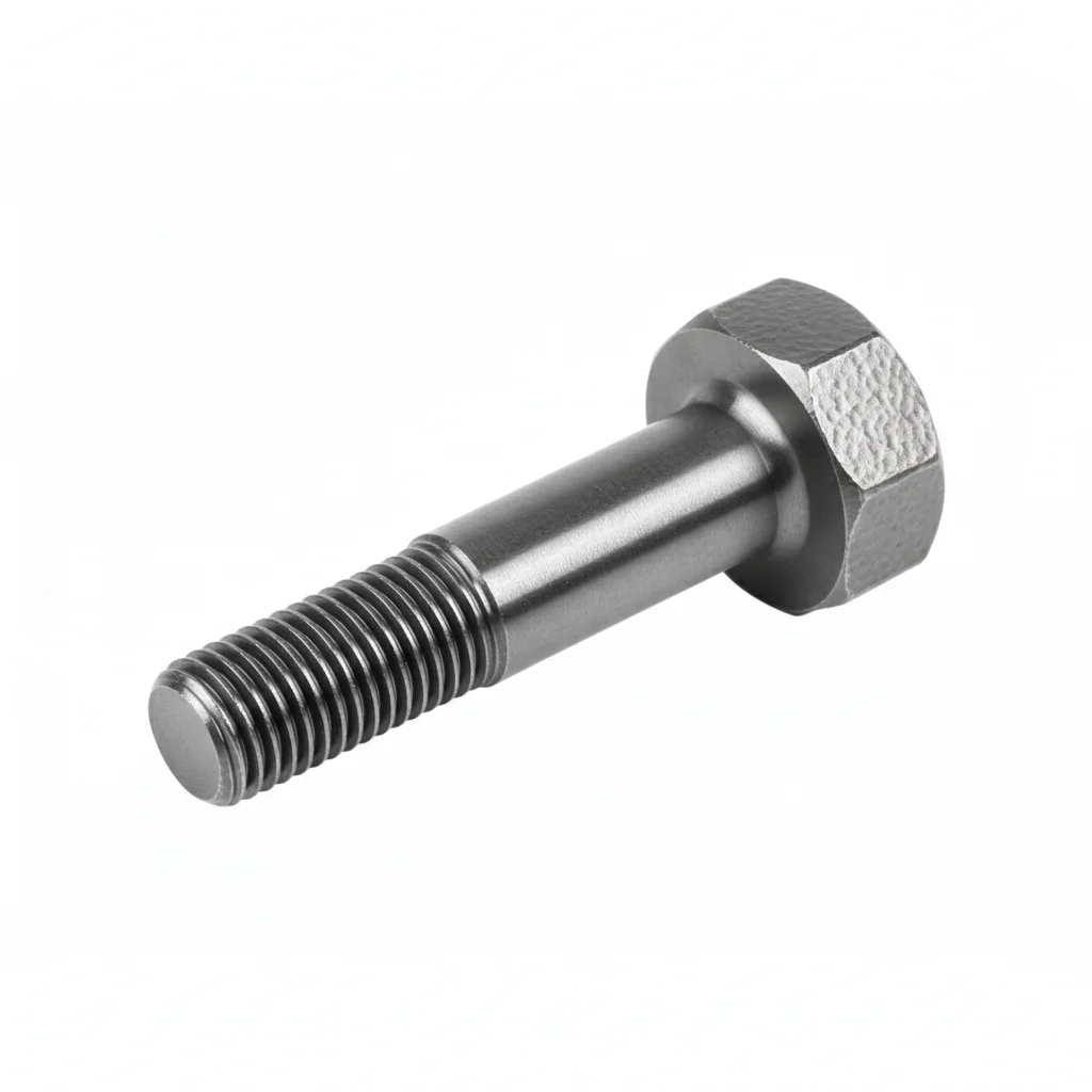
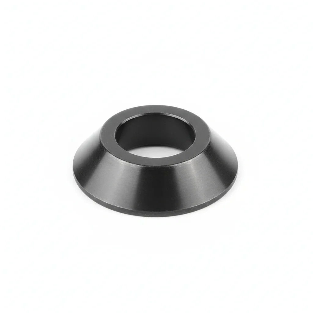
| Flywheel Flange Bolt | Heavy-Duty Disc Spring Washer | |
|---|---|---|
| SPEC | M14-M20 Fine Thread | M14-M20 |
| MATERIAL | 42CrMoA | 60Si2Mn |
| GRADE | 12.9 Grade | Dacromet |
| FINISH | HDG >=55um per ISO 1461 | HDG >=55um per ISO 1461 |
| CORROSION | C3 (ISO 12944-2) | C3 (ISO 12944-2) |
| TEMP | -20°C to +80°C | -20°C to +80°C |
| WEIGHT | ~0.5 kg/piece | ~0.5 kg/piece |
| MOQ | 100 pcs | 100 pcs |
| PACK | VCI paper + carton | VCI paper + carton |
| STD | ISO 898-1, GB/T 3098.1 | ISO 898-1, GB/T 3098.1 |
| USE | Engine Flywheel Connection | Elastic Compensation at High-Temperature Joints |
PROCEDURE
- Degrease mating flanges and bolt bores with acetone; verify surface flatness to within 0.1mm per 100mm using a straightedge.
- Place the 60Si2Mn disc spring washer (Dacromet coated) under the head of each 12.9-grade fine-thread bolt, oriented per drawing.
- Hand-start all bolts, then tighten in a cross-symmetrical pattern in 3 stages to the torque specified in the OEM manual (use a calibrated wrench).
- After the final pass, mark each bolt head, washer, and flange with torque seal paint; photograph the assembly for QA records.
- Verify preload by checking that no bolt has rotated relative to the paint mark during the first 10 minutes of engine run.
COMMON ERRORS
| ✕ WRONG | CONSEQUENCE | ✓ CORRECT |
|---|---|---|
| Reusing old bolts or mixing bolts from different batches without full-set replacement | Fatigue damage from prior service is undetected; a bolt fractures at the 3000h inspection point, flinging fragments into the converter housing and causing a fire. | Install a complete new set of 12.9-grade fine-thread bolts (42CrMoA) with matching disc spring washers, and record batch numbers. |
| Tightening in a circular pattern instead of cross-symmetrical 3-stage sequence | Uneven clamp load distorts the flywheel flange, causing preload scatter and early fatigue cracks in highly loaded bolts. | Tighten in a cross-symmetrical pattern in 3 stages, using the torque values specified in the OEM manual. |
| Omitting thread locking adhesive or safety wire on flywheel bolts | Vibration from torque pulses backs off a bolt; preload decays, the joint frets, and the bolt loosens completely, leading to coupling separation. | Apply thread locking adhesive to the fine threads and install safety wire in groups of 2-3 bolts per the maintenance procedure. |
MAINTENANCE
At each 3000h overhaul, perform magnetic particle testing on all bolts; if any crack is found or torque decay exceeds 20%, replace the entire set synchronously. Also verify disc spring washer condition and re-torque any bolt below 80% of specified torque.
B · Large Mining
C4 Harsh per ISO 12944-2
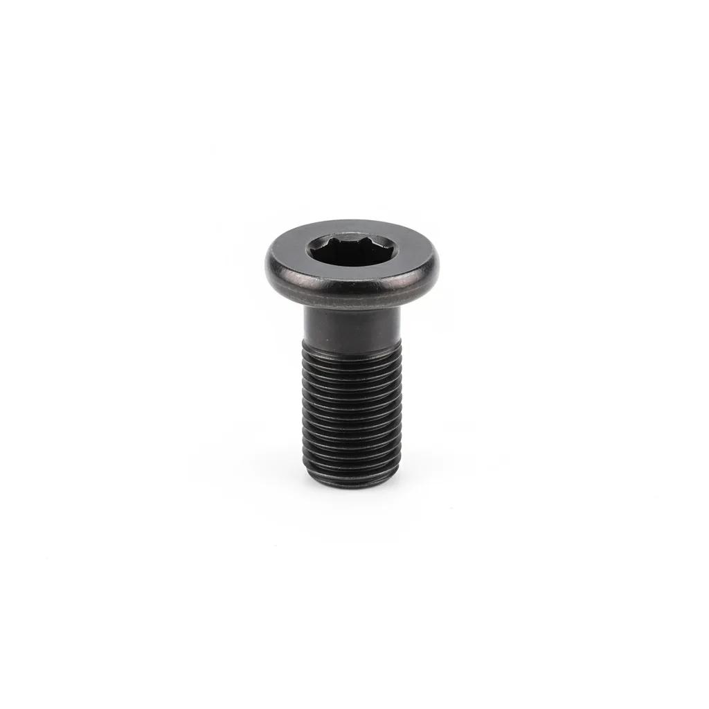
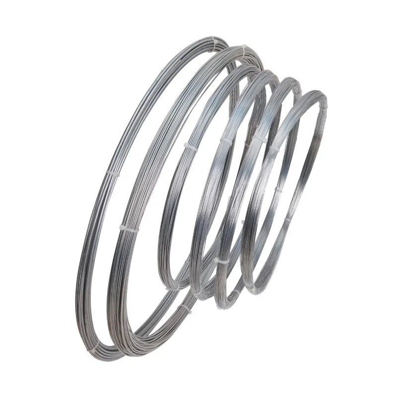
| Flywheel Bolt | Safety Wire | |
|---|---|---|
| SPEC | M20-M24 Fine Thread | φ0.8-1.2mm |
| MATERIAL | 42CrMoA | 304 |
| GRADE | 12.9 Grade | — |
| FINISH | HDG >=55um per ISO 1461 | HDG >=55um per ISO 1461 |
| CORROSION | C3 (ISO 12944-2) | C3 (ISO 12944-2) |
| TEMP | -20°C to +80°C | -20°C to +80°C |
| WEIGHT | ~0.5 kg/piece | ~0.5 kg/piece |
| MOQ | 100 pcs | 100 pcs |
| PACK | VCI paper + carton | VCI paper + carton |
| STD | ISO 898-1, GB/T 3098.1 | ISO 898-1, GB/T 3098.1 |
| USE | Large Mining Equipment Flywheel | Bolt Locking Safety |
PROCEDURE
- Clean the flywheel flange and bolt holes with acetone to remove grease and debris, ensuring a dry surface.
- Apply a thread locking adhesive suitable for fine threads to the M20-M24 bolts, then insert them in the cross-tightening sequence.
- Tighten the bolts in three stages using a calibrated torque wrench to achieve the specified preload for 12.9 grade.
- After torquing, thread the 304 stainless steel safety wire (φ0.8-1.2mm) through the bolt heads in groups of 2-3, ensuring the wire pulls in the tightening direction.
- Perform a final visual inspection to confirm all safety wires are properly tensioned and no bolt heads show signs of over-torquing or damage.
COMMON ERRORS
| ✕ WRONG | CONSEQUENCE | ✓ CORRECT |
|---|---|---|
| Reusing bolts that have been in service for 3000 hours without inspection | Fatigue cracks may have initiated, leading to sudden fracture and flywheel debris penetrating the converter housing, causing fire. | Disassemble and inspect all flywheel bolts at each 3000-hour service interval using magnetic particle testing; replace the entire set if any crack or torque decay >20% is found. |
| Threading safety wire in the loosening direction | The wire becomes slack when a bolt loosens, failing to prevent the bolt from flying off. | Route the safety wire so that the loosening of one bolt tightens the next, maintaining tension across the group. |
MAINTENANCE
At each overhaul window (typically every 3000 operating hours per safety requirement), inspect all flywheel bolts for torque decay and cracks using magnetic particle testing; if torque decay >20% or any crack is detected, replace the entire set synchronously. Additionally, check safety wire for damage or slack and replace if necessary.
Plan C · Mining/Extreme Conditions
C5-M Extreme per ISO 12944-2
| Flywheel Bolt | Safety Wire | |
|---|---|---|
| SPEC | M20-M24 Fine Thread | φ0.8-1.2mm |
| MATERIAL | 42CrMoA | 316L |
| GRADE | 12.9 Grade | — |
| FINISH | HDG >=55um per ISO 1461 | HDG >=55um per ISO 1461 |
| CORROSION | C3 (ISO 12944-2) | C3 (ISO 12944-2) |
| TEMP | -20°C to +80°C | -20°C to +80°C |
| WEIGHT | ~0.5 kg/piece | ~0.5 kg/piece |
| MOQ | 100 pcs | 100 pcs |
| PACK | VCI paper + carton | VCI paper + carton |
| STD | ISO 898-1, GB/T 3098.1 | ISO 898-1, GB/T 3098.1 |
| USE | Extreme Conditions / Maximum Protection | Extreme Conditions / Maximum Protection |
PROCEDURE
- Degrease the mating surfaces with MEK solvent and verify surface roughness Ra <1.6um using a profilometer.
- Apply a marine-grade anti-corrosion joint compound rated for -50°C to 200°C, and use PTFE-encapsulated washers to prevent galvanic corrosion.
- Align the flywheel within 0.3mm and tighten the M20-M24 bolts using a hydraulic tensioner to achieve precise preload for 12.9 grade.
- Perform PMI (Positive Material Identification) on a 10% sample of bolts to confirm 42CrMoA material, and document results for compliance audit.
- Conduct dye penetrant testing on a 10% sample of bolts to detect surface cracks; replace any with indications.
- Apply protective sealant to all exposed fastener surfaces and install permanent condition monitoring instrumentation to track preload and corrosion.
COMMON ERRORS
| ✕ WRONG | CONSEQUENCE | ✓ CORRECT |
|---|---|---|
| Using 304 safety wire instead of 316L in extreme corrosive environments | 304 may suffer pitting corrosion in chloride-rich environments, compromising the locking function and allowing bolt loosening. | Specify 316L stainless steel safety wire for superior corrosion resistance, especially in mining or marine conditions. |
| Skipping the use of PTFE-encapsulated washers between dissimilar metals | Galvanic corrosion can occur, with corrosion rate up to 0.2mm/year, reducing fatigue life to 30% of design. | Always use insulating washers or coatings to isolate the 42CrMoA bolts from the stainless steel substrate, preventing galvanic coupling. |
MAINTENANCE
At each scheduled overhaul (per OEM guidance, around 3000 operating hours), perform magnetic particle inspection on all bolts and replace the set if any crack or torque decay >20% is found. Additionally, monitor corrosion using the installed instrumentation; replace fasteners if corrosion affects >5% of surface area or pitting depth exceeds 0.3mm. For extreme environments, consider more frequent checks based on operational severity.
SPEC MATRIX
Product Specifications Covered for This Scenario
Specifications from the Yaxiio product catalog. Weights are theoretical calculated values.
| DIA | LENGTH | MATERIAL | GRADE | FINISH | SKU | UNIT WEIGHT |
|---|---|---|---|---|---|---|
| M12 | 30, 35, 40, 45, 50, 60, 70, 80 | Alloy Steel | 10.9S | Black Oxide | 8 | 42–86 g |
| M16 | 40–120 (10 sizes) | Alloy Steel | 10.9S | Black Oxide | 10 | 98–220 g |
| M20 | 45–160 (11 sizes) | Alloy Steel | 10.9S | Black Oxide | 11 | 180–460 g |
| M24 | 50–200 (12 sizes) | Alloy Steel | 10.9S | Black Oxide | 12 | 300–830 g |
| M30 | 60–240 (12 sizes) | Alloy Steel | 10.9S | Black Oxide | 12 | 570–1500 g |
REFERENCED STANDARDS
References
SUPPLIER CAPABILITY
Quality, Delivery & Customization
Quality Control
- ✓MTC material certificates with every batch
- ✓Key parts sampled for hardness/salt spray/torque coefficient
- ✓100% inspection or AQL sampling before shipment
Delivery
- ✓Standard parts made to order: 7-15 days
- ✓Custom parts: 25-45 days
- ✓FOB/CIF/DDP supported
Customization
- ✓Drawing review and material matching
- ✓Non-standard sizes/heads/threads
- ✓Small-batch prototyping supported
Certification
- ✓Material certificates (MTC)
- ✓Spectrographic analysis reports
- ✓Salt spray test reports (on request)
MOQ: No MOQ for standard parts; custom parts assessed by process complexity
FAQ
Frequently Asked Questions
RELATED READING
Keep Reading & Next Step
BEYOND TECHNICAL SPECS
Finding the right factory, controlling quality, delivering on time — that's the real challenge. We cover fasteners, rubber, plastics, industrial textiles. One team, end to end.
SEE CAPABILITIES →