Duct Hanger Expansion Bolt Pullout: Prevention and Fix
A large duct (section 2m×1m) can weigh several hundred kilograms including its own weight, insulation, and accumulated dust—suspended from the ceiling by hanger expansion bolts. If any expansion bolt pulls out of the concrete → hanger fails → duct sags locally → load on adjacent hangers doubles → chain reaction pullout → tens of meters of duct fall from height → smashing equipment and pipelines below. This page explains how to select and specify duct hanger fasteners to avoid this failure chain
RISK AUDIT // ENGINEERING DIAGNOSIS
Procurement Pitfall Guide
"Specifying the wrong anchor or latch for a ventilation duct can turn routine airflow into a falling hazard."
QC-AUDIT // REV.5
SCALE 1:1 · 03 ITEMS
RISK-01
Expansion bolts for duct hangers pull out from concrete under long-term vibration
Corrective Measures
RISK-02
Access door lock rusts shut, preventing emergency opening
Corrective Measures
RISK-03
Duct flange bulges open in positive pressure systems
Corrective Measures
FIELD-SPECIFIC INSIGHT
Duct Hanger Failure Chain: What to Check in Procurement
The most overlooked risk in industrial ventilation is the cumulative slip of expansion bolts under long-term vibration. Even if each bolt meets static load requirements, micron-level slip over years can cause visible sagging and load redistribution, leading to catastrophic failure
WHAT TO CHECK
- 1Specify undercut mechanical anchors (M10-M16) for duct hangers in concrete; avoid standard expansion bolts in vibration zones
- 2For heavy ducts, use through rods with Grade 8.8 hot-dip galvanized steel to eliminate pullout risk
- 3Ensure bolt spacing on high-pressure duct flanges is reduced to 100 mm (not 150 mm) to prevent flange bulging and gasket blowout
- 4Include torque verification in installation: re-torque any fastener below 80% of specified torque during first 6-month inspection
| Check | Why it matters | What to specify |
|---|---|---|
| Anchor type for duct hanger | Standard expansion bolts slip under vibration, causing cumulative sag and potential chain-reaction pullout | Undercut mechanical anchor M10-M16, carbon steel zinc-plated (C3) or HDG (C4) |
| Bolt material and coating | Corrosion in moist airflow reduces load capacity; rusted access door locks prevent emergency opening | 304 stainless steel for access door latches; 316L for fire-rated smoke exhaust ducts |
| Flange bolt spacing | Excessive spacing causes flange bulging under positive pressure, leading to gasket blowout and air leakage | Use Grade 8.8 bolts with proper preload |
| Maintenance schedule | Undetected corrosion or loosening can lead to sudden failure | Inspect every 250 operating hours or 6 months; replace fasteners with >5% corrosion or pitting depth exceeding project limits |
All torque values and inspection intervals should be verified against project-specific conditions and applicable standards (SMACNA, GB 50243)
Evidence level: source-page-only
INDUSTRY TECH REFERENCE
How Fan Vibration Rattles Duct Flanges into Leaks
In industrial ventilation, the most common duct-flange failure is not impact damage — it is being rattled loose by fan vibration. From one slack bolt or spring clamp to over-limit dust in the workshop, every step is chained to the one before, and every link carries a checkable figure.
- 1The vibration source is the fan: about 40% of rotating-machinery vibration sources are imbalance and at least 30% misalignment; the fan-body criterion is zone B ceiling 4.5 mm/s RMS (long-term operation) with a common first alarm at 7.1 mm/s
- 2Vibration travels down the duct: fan vibration carries through the duct shell to every flange node, where bolts and spring clamps take long-term micro-rattling, compounded by fan start-stop and airflow pulsation
- 3Preload decays into loosening: the rattling steadily consumes bolt and clamp preload, slack starts at the joint edge, and flange gaps gradually appear
- 4Leakage cuts airflow: leaking flange gaps reduce system airflow, and the capture-hood collection efficiency drops with it
- 5The occupational endpoint: insufficient capture means over-limit dust in the workshop — exactly why commissioning acceptance and routine inspection put flange seams on the checklist
- 6The interception, matched to GB 50243-2016: high-pressure system flange bolt/rivet spacing ≤100 mm, low/medium-pressure systems ≤150 mm; bolt sizes M6 (small) / M8 (large); rectangular flanges must have corner bolt holes — leak inspection plus retightening to spec
About 40% of rotating-machinery vibration sources from imbalance and at least 30% from misalignment are order-of-magnitude estimates; the fan zone-B ceiling of 4.5 mm/s and the 7.1 mm/s alarm are ISO 10816-3 zone criteria, and the ≤150/≤100 mm spacing with M6/M8 corner holes are GB 50243-2016 clauses — directly checkable.
INDUSTRY TECH REFERENCE
Ventilation Duct Joint Fasteners: Acceptance Numbers for Sizes, Spacing and Interfaces
Duct-joint fastener acceptance does not run on 'looks about right' — hole spacing, bolt sizes, clamp intervals and flexible-connector length all have defined figures, and putting them in the RFQ and acceptance sheet gives you the basis. Reading the Chinese and North American systems side by side, nothing is missed.
| Joint / interface | Fastener and size | Key figures | Maintenance and acceptance |
|---|---|---|---|
| Angle-flange connection | Bolts + nuts + gasket; bolt size M6 (small) / M8 (large) | Bolt and rivet spacing: ≤150 mm for low/medium-pressure systems, ≤100 mm for high-pressure systems; rectangular flanges must have corner bolt holes | Leak inspection; retighten to size spec when slack |
| Thin-gauge standing-seam (co-molded) flange | Spring clamps / U-type fastener bolts (galvanized) | Spring-clamp interval ≤150 mm, ≤100 mm for clean-room service; alternate fixing direction front-and-back | Visual seam check plus leak inspection |
| Fan-to-duct flexible connector | Bar-strip bolts | Flexible connector length 150–250 mm; smoke-extract systems must use non-combustible material | Replace on aging |
| Expansion joint on long straight runs | Expansion-joint fasteners | Straight runs longer than 20 m must have an expansion joint | Check together with the connected section |
| North American comparison (SMACNA TDC/TDF) | 3/8″ (9.5 mm) corner bolts + 6″ (152 mm) cleat/spring-clamp system | The 6″ refers to cleat pitch — not the same object as the GB 150 mm bolt spacing | Accept under one system (GB or SMACNA) per project; do not mix the two |
No order-of-magnitude estimates are used in this slot.
INDUSTRY TECH REFERENCE
Which Standards Govern Duct Hardware: Chinese, North American and Combustible-Dust Systems
Duct fasteners are not covered by a single bolt standard: construction acceptance, North American construction, spark-resistant classification and the combustible-dust umbrella each own a segment. Before quoting, know which standard governs the part you are buying.
The standards listed in this slot are all public standards; only standard numbers, editions and scope are given for procurement navigation — specific acceptance values are per the current clauses of each standard. No order-of-magnitude estimates are used in this slot.
INDUSTRY TECH REFERENCE
Combustible-Dust Duty: How Spark-Resistant Construction Changes Fastener Matching for Ducts and Collectors
With wood, metal, grain or plastic dust in play, the dust collector and its ductwork are an explosion-risk zone — the spark-resistant class directly changes the material of components in the airstream, and the fastener pairing follows. Establish the class first, then quote the scheme.
Combustible-dust systems are managed under NFPA 660:2025 — it consolidates six dust standards, NFPA 652/654/61/484/655/664, and puts both the dust collector and its ductwork in the explosion-risk zone. Fan spark-resistant construction classes under AMCA 99-0401: Type C adds non-ferrous baffles at the inlet cone and shaft penetration; Type B makes the impeller itself non-ferrous, usually aluminum; Type A makes every airstream component non-ferrous, including the volute. The higher the class, the more complete the non-ferrous conversion of the air path, and the fastener material pairing plus strength checks change with it — put the spark-resistant class on the RFQ and have the supplier propose a matching fastener package per class, not a blanket 'stainless parts'. Two procurement red lines: ① vent-panel bolts open at the NFPA 68:2023 design pressure and are safety parts — never tighten them down arbitrarily; 'a bit tighter is safer' is the reverse move on an explosion vent; ② fold dust accumulation and equipment grounding into the same inspection round (the front-line North American troubleshooting order: grounding is the first question).
No order-of-magnitude estimates are used in this slot.
INDUSTRY TECH REFERENCE
High-Temperature Exhaust Flange Fastening: Thermal Growth, Heat-Resistant Steel and Hot Recheck
On hot exhaust systems, the flange is not threatened by 'being loose' — thermal growth pushes the joint apart, and warping, seizure and loss of strength are three roads to the same leak. There is no 'check it once, ten years covered' in this duty.
The high-temperature reference is a 925°F (≈496°C) hot-gas fan installation: the volute uses center-mounted support to isolate heat conduction, the bearing zone gets 4-inch insulation, and the flanges are rated ANSI Class 150 against high-temperature warping — flange rating and insulation are standard practice on hot systems, not options. High-temperature flange bolts end up in heat-resistant steel, but the temperature boundaries between carbon steel, stainless steel and heat-resistant alloy have no authoritative published figures (a registered industry gap) — put the service temperature on the RFQ and ask the supplier for strength data at that temperature instead of a quote on the word 'heat-resistant'. On the maintenance side: hot flanges need a hot-recheck regime (modeled on the hot-bolting practice of piping systems; this domain has no dedicated code), and service-temperature records belong in the review — on hot duty the retorque cycle follows the actual service temperature, not the calendar.
No order-of-magnitude estimates are used in this slot.
PLAN COMPARISON
Three-Plan Core Parameter Comparison
Compare row by row. Click column headers to jump to plan details.
| A · A · General | B · B · Heavy Duty / Fire Protection | C · Plan C · Explosion-Proof / Cleanroom | |
|---|---|---|---|
| 1. UNDER-CUT MECHANICAL ANCHOR | |||
| SPEC | M10-M16 | M12-M16 | M12-M16 |
| MATERIAL | Carbon Steel, Zinc-Plated | Grade 8.8, Hot-Dip Galvanized | Grade 8.8, Hot-Dip Galvanized |
| FINISH | HDG >=55um per ISO 1461 | HDG >=55um per ISO 1461 | HDG >=55um per ISO 1461 |
| 2. ACCESS DOOR LATCH | |||
| SPEC | Universal | Fire-Rated | Fire-Rated |
| MATERIAL | 304 | 316L | 316L |
| FINISH | HDG >=55um per ISO 1461 | HDG >=55um per ISO 1461 | HDG >=55um per ISO 1461 |
SELECTION GUIDE
Which Fastener Solution Fits Your Ductwork?
| Operating condition | Recommended option | Key basis |
|---|---|---|
| General ductwork (C3 Standard per ISO 12944-2); hanging points under 50kg | Plan A · General: undercut mechanical anchor M10-M16 (carbon steel, zinc-plated) for duct hangers + universal 304 access door latch | ETAG 001 metal anchors; SMACNA duct construction standard |
| Heavy duty / fire protection: large ducts (section 2m×1m, several hundred kg including its own weight, insulation, and accumulated dust) with smoke exhaust and fire-rating duty | Plan B · Heavy Duty / Fire Protection: through rod M12-M16 (Grade 8.8, hot-dip galvanized) for large duct hangers + fire-rated 316L escape door lock for fire smoke exhaust duct access doors | SMACNA duct construction standard; GB 50243 ventilation and air conditioning construction |
| Explosion-proof areas / cleanrooms / high-temperature smoke exhaust (C5-M Extreme per ISO 12944-2) | Plan C · Explosion-Proof / Cleanroom: full 304/316 stainless steel range + anti-static grounding + ATEX certification; through rod M12-M16 (Grade 8.8 hot-dip galvanized) + fire-rated 316L escape door lock | GB 50243; SMACNA duct construction standard |
| High-pressure ducts (>1000Pa): positive pressure bulges the flange joint open, gasket blows out, system airflow loss 15-30% | Reduce flange bolt spacing to ≤100mm (150mm spacing acceptable for medium/low pressure <500Pa); use closed-cell sponge rubber gasket; after installation check flange joints with an anemometer — if local velocity >2m/s, retighten or add bolts | SMACNA duct construction standard; GB 50243 |
| Long-term vibration duty: expansion bolts slip by microns cumulatively (5-10mm over 3-5 years), duct sags visibly | Prefer undercut mechanical anchors or through-bolts through the slab instead of expansion bolts (expansion bolts only suitable for hanging points <50kg); inspect duct levelness quarterly with a laser level — reinforce any hanging point with sag >10mm immediately | ETAG 001 metal anchors |
A · General
C3 Standard per ISO 12944-2
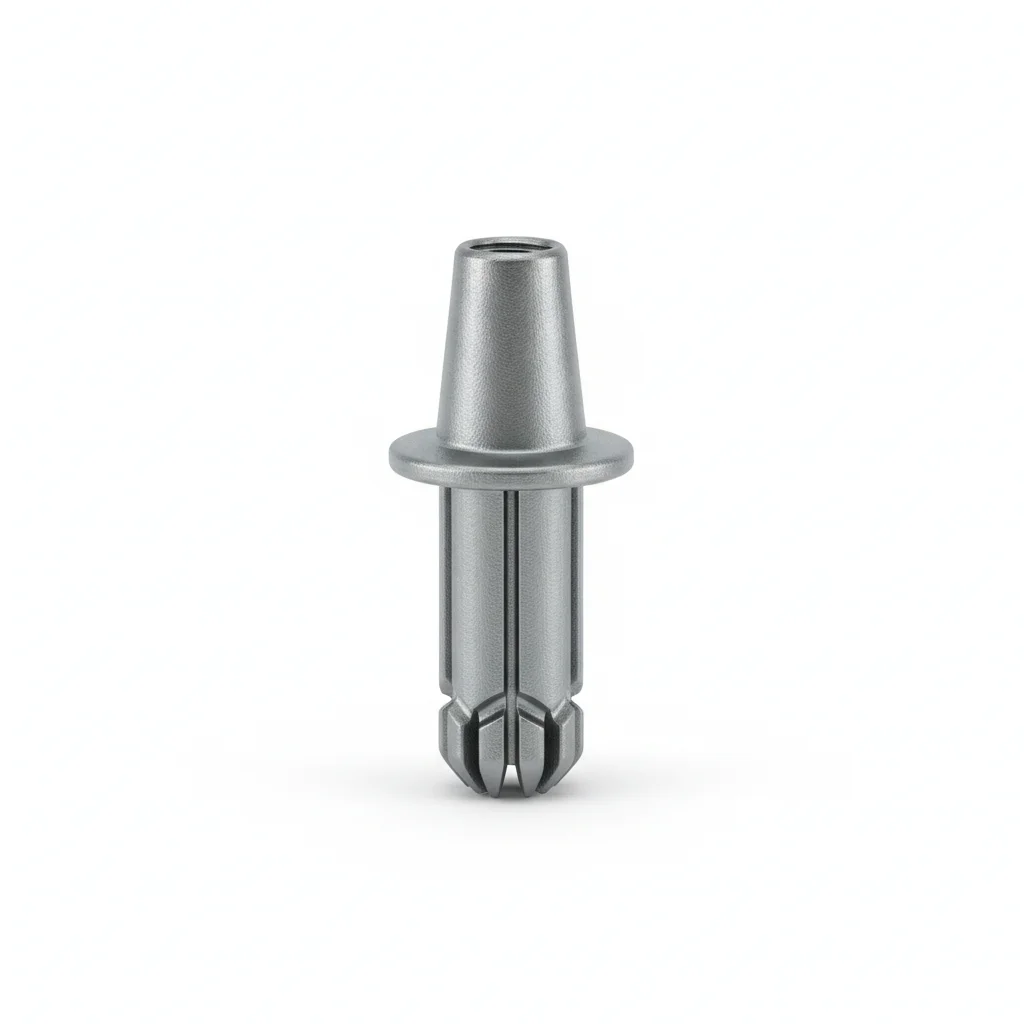
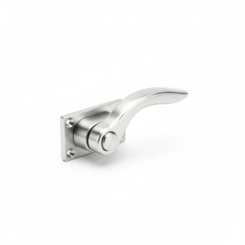
| Under-cut Mechanical Anchor | Access Door Latch | |
|---|---|---|
| SPEC | M10-M16 | Universal |
| MATERIAL | Carbon Steel, Zinc-Plated | 304 |
| GRADE | — | — |
| FINISH | HDG >=55um per ISO 1461 | HDG >=55um per ISO 1461 |
| CORROSION | C3 (ISO 12944-2) | C3 (ISO 12944-2) |
| TEMP | -20°C to +80°C | -20°C to +80°C |
| WEIGHT | ~0.5 kg/piece | ~0.5 kg/piece |
| MOQ | 100 pcs | 100 pcs |
| PACK | VCI paper + carton | VCI paper + carton |
| STD | ISO 898-1, GB/T 3098.1 | ISO 898-1, GB/T 3098.1 |
| USE | Duct Hanger | Duct Access Door |
PROCEDURE
- Drill the concrete substrate to the depth specified for the M10-M16 undercut anchor, then brush and blow the hole clean of dust before setting the anchor.
- Insert the undercut anchor and expand it with the setting tool until the sleeve engages the hole undercut, verifying no rotation or pullout under hand force.
- Attach the duct hanger bracket, place the zinc-plated washer and nut, and tighten to the manufacturer's recommended torque for the selected M10-M16 size.
- After tightening, mark the nut and bolt with a paint pen to reveal any future loosening, and record the torque value for each hanger in the installation log.
- Use a laser level along the duct bottom to confirm no sag exceeds 10mm at any hanger point before commissioning airflow.
COMMON ERRORS
| ✕ WRONG | CONSEQUENCE | ✓ CORRECT |
|---|---|---|
| Using a standard expansion bolt instead of an undercut anchor for a hanger point rated above 50kg | Vibration from the fan and airflow causes micron-level slip that accumulates to 5-10mm over 3-5 years, leading to duct sag and potential chain-reaction pullout. | Select an undercut mechanical anchor (M10-M16) for all hanger points; reserve expansion bolts for hanging points under 50kg. |
| Installing the anchor into a hole that is too shallow or not cleaned of debris | The expansion sleeve cannot grip the hole wall fully, so the bolt pulls out under static load or after minimal vibration, dropping the duct section. | Drill to the anchor manufacturer's specified depth, then brush and blow out the hole completely before inserting and setting the anchor. |
MAINTENANCE
Check duct levelness quarterly with a laser level; reinforce any hanger point showing sag greater than 10mm immediately. At each overhaul window, verify torque on a 10% sample of hanger bolts and re-torque any that have loosened.
B · Heavy Duty / Fire Protection
C4 Harsh per ISO 12944-2
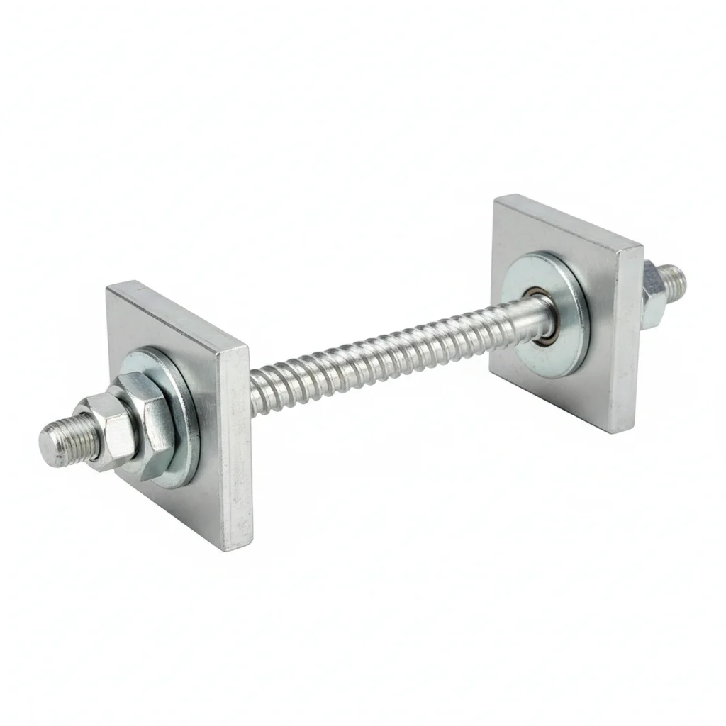
| Through Rod | Fire Escape Door Lock | |
|---|---|---|
| SPEC | M12-M16 | Fire-Rated |
| MATERIAL | Grade 8.8, Hot-Dip Galvanized | 316L |
| GRADE | — | — |
| FINISH | HDG >=55um per ISO 1461 | HDG >=55um per ISO 1461 |
| CORROSION | C3 (ISO 12944-2) | C3 (ISO 12944-2) |
| TEMP | -20°C to +80°C | -20°C to +80°C |
| WEIGHT | ~0.5 kg/piece | ~0.5 kg/piece |
| MOQ | 100 pcs | 100 pcs |
| PACK | VCI paper + carton | VCI paper + carton |
| STD | ISO 898-1, GB/T 3098.1 | ISO 898-1, GB/T 3098.1 |
| USE | Large Duct Hanger | Fire Smoke Exhaust Duct Access Door |
PROCEDURE
- Clean the concrete drill holes and rod surfaces with compressed air and a wire brush to remove dust and debris, ensuring a clean bonding surface for the through rod.
- Insert the M12-M16 Grade 8.8 hot-dip galvanized through rod through the slab, positioning it so that the threaded portion extends evenly above and below the concrete.
- Place heavy-duty washers and nuts on both ends, then tighten the lower nut to snug the rod against the duct hanger bracket.
- Tighten the upper nut in a cross-pattern sequence to achieve the specified preload, using a calibrated torque wrench and recording the final torque value.
- Verify the hanger is level and the rod is vertical; adjust if necessary. Apply a corrosion-inhibiting coating to the exposed threads and nut assemblies to maintain the HDG protection.
COMMON ERRORS
| ✕ WRONG | CONSEQUENCE | ✓ CORRECT |
|---|---|---|
| Using a standard expansion bolt instead of a through rod for heavy duct hangers | Expansion bolts can slip under vibration, leading to cumulative sag and eventual pullout, causing the duct to fall. | For heavy ducts (over 50kg per hanger), specify through rods (M12-M16, Grade 8.8) that pass through the slab, eliminating pullout risk. |
| Neglecting to apply anti-seize or corrosion protection on the threaded rod during installation | Moisture and corrosive agents can attack the threads, leading to rust and reduced load capacity over time. | Apply a suitable anti-seize compound or corrosion inhibitor to the threads and exposed surfaces before installation, especially in C4 environments. |
MAINTENANCE
Inspect hanger assemblies every 250 operating hours or 6 months, whichever comes first. Check for any visible sagging of the duct using a laser level; if sag exceeds 10mm, immediately reinforce the hanger. Re-torque any nuts that have loosened below 80% of specified torque. Replace any rods or nuts showing corrosion affecting more than 5% of surface area or pitting depth greater than 0.3mm. Document all inspections and actions in the maintenance log.
Plan C · Explosion-Proof / Cleanroom
C5-M Extreme per ISO 12944-2
| Through Rod | Fire Escape Door Lock | |
|---|---|---|
| SPEC | M12-M16 | Fire-Rated |
| MATERIAL | Grade 8.8, Hot-Dip Galvanized | 316L |
| GRADE | — | — |
| FINISH | HDG >=55um per ISO 1461 | HDG >=55um per ISO 1461 |
| CORROSION | C3 (ISO 12944-2) | C3 (ISO 12944-2) |
| TEMP | -20°C to +80°C | -20°C to +80°C |
| WEIGHT | ~0.5 kg/piece | ~0.5 kg/piece |
| MOQ | 100 pcs | 100 pcs |
| PACK | VCI paper + carton | VCI paper + carton |
| STD | ISO 898-1, GB/T 3098.1 | ISO 898-1, GB/T 3098.1 |
| USE | Extreme Conditions / Maximum Protection | Extreme Conditions / Maximum Protection |
PROCEDURE
- Thoroughly degrease the through rod and concrete hole with MEK solvent to remove all contaminants, ensuring a clean surface for maximum bonding and corrosion resistance.
- Apply a marine-grade anti-corrosion compound rated for -50 to 200°C to the rod and nut threads, and use PTFE-encapsulated washers to prevent galvanic corrosion in the extreme environment.
- Insert the rod through the slab and position the duct hanger bracket. Tighten the nuts using a hydraulic tensioner to achieve the precise preload, ensuring even load distribution.
- Verify the rod alignment within 0.3mm using a dial indicator. Perform PMI (Positive Material Identification) on a 10% sample of rods to confirm Grade 8.8 material composition.
- Conduct a dye penetrant test on 10% of the installed assemblies to detect any surface cracks; replace any rod showing indications. Apply a protective sealant over the exposed threads and nuts, and install permanent condition monitoring instrumentation for continuous assessment.
COMMON ERRORS
| ✕ WRONG | CONSEQUENCE | ✓ CORRECT |
|---|---|---|
| Using carbon steel fasteners without adequate corrosion protection in a cleanroom or explosion-proof area | Corrosion can contaminate the cleanroom environment or create sparks in explosive atmospheres, leading to safety hazards and system failure. | Specify full 304/316 stainless steel fasteners with anti-static grounding and ATEX certification for these extreme conditions. |
| Failing to verify material grade and coating integrity before installation in a high-corrosion environment | Substandard materials may fail prematurely, causing duct collapse and potential damage to sensitive equipment or processes. | Perform PMI testing on a representative sample and visually inspect the HDG coating thickness (>=55um per ISO 1461) to ensure compliance with the C5-M specification. |
MAINTENANCE
Inspect all fasteners and hangers every 250 operating hours or 6 months, whichever comes first. Use condition monitoring data to detect any loss of preload or corrosion activity. Re-torque any fasteners below 80% of specified torque. Replace any fastener with corrosion affecting more than 5% of surface area or pitting depth exceeding 0.3mm. Every 3 years, perform a full disassembly and inspection of a 20% sample; every 5 years, replace all critical fasteners regardless of condition. Document all findings in the compliance report for regulatory review.
REFERENCED STANDARDS
References
SUPPLIER CAPABILITY
Quality, Delivery & Customization
Quality Control
- ✓MTC material certificates with every batch
- ✓Key parts sampled for hardness/salt spray/torque coefficient
- ✓100% inspection or AQL sampling before shipment
Delivery
- ✓Standard parts made to order: 7-15 days
- ✓Custom parts: 25-45 days
- ✓FOB/CIF/DDP supported
Customization
- ✓Drawing review and material matching
- ✓Non-standard sizes/heads/threads
- ✓Small-batch prototyping supported
Certification
- ✓Material certificates (MTC)
- ✓Spectrographic analysis reports
- ✓Salt spray test reports (on request)
MOQ: No MOQ for standard parts; custom parts assessed by process complexity
FAQ
FAQ
RELATED READING
Keep Reading & Next Step
BEYOND TECHNICAL SPECS
Finding the right factory, controlling quality, delivering on time — that's the real challenge. We cover fasteners, rubber, plastics, industrial textiles. One team, end to end.
SEE CAPABILITIES →