
Pulley Lagging Material Comparison for Mining Conveyor Hardware
Select the right lagging material—natural rubber, polyurethane, or ceramic composite—based on load, moisture, and temperature. Each option has distinct wear resistance, friction coefficient, and bonding requirements that affect belt life and maintenance downtime
RISK AUDIT // ENGINEERING DIAGNOSIS
Procurement Pitfall Guide
"Field failures in dry conveyor drives — and how to avoid them."
QC-AUDIT // REV.5
SCALE 1:1 · 03 ITEMS
RISK-01
Roller lagging detachment causes belt slippage and wear
Corrective Measures
RISK-02
Abnormal wear due to improper lagging material selection
Corrective Measures
RISK-03
Sudden failure due to lack of wear monitoring
Corrective Measures
FIELD-SPECIFIC INSIGHT
Lagging Material Selection: Key Differences in Wear, Friction, and Bonding
Pulley lagging prevents belt slippage and protects the belt from wear. The three common materials—natural rubber (NR), polyurethane (PU), and ceramic composite—differ in hardness, friction coefficient, temperature resistance, and bonding method. Choosing the wrong material can lead to premature wear, detachment, or belt damage
WHAT TO CHECK
- 1NR 60A diamond pattern: friction coefficient >0.4, suitable for dry, light-load conditions; life 5000-8000 hours; cold-bonding adhesive with initial adhesion ≥2N/mm
- 2PU 80A herringbone groove: wear resistance improved over NR, friction coefficient >0.5, life 12000-18000 hours; requires polyurethane-specific adhesive with shear strength ≥8MPa
- 3Ceramic composite (Al2O3 tiles in PU matrix): friction coefficient >0.6, temperature resistance up to 200°C, life 25000-35000 hours; uses special alloy bolts (Inconel 625) and modular mounting base
- 4Lagging detachment risk: when remaining thickness <3mm, countersunk bolts expose → belt back scratches → strength drops from 100% to 60%. Replace immediately at <3mm, not when bolts are exposed
- 5For wet/sticky materials with moisture >10%, PU or ceramic is recommended; NR may cause slippage and accelerated wear
| Check | Why it matters | What to specify |
|---|---|---|
| Material hardness (Shore A) | Hardness affects wear rate and friction; too soft wears quickly, too hard may damage belt | Specify Shore A durometer per ASTM D2240; e. G. , NR 60A, PU 80A |
| Friction coefficient (dry/wet) | Determines belt drive traction; insufficient friction causes slippage and belt wear | Request manufacturer test data for friction coefficient under expected conditions; minimum >0.4 dry |
| Bonding method and adhesion strength | Weak bond leads to lagging detachment, exposing bolts and damaging belt | For NR: cold-bonding adhesive with initial adhesion ≥2N/mm. For PU: polyurethane-specific adhesive with shear strength ≥8MPa |
| Wear life under actual load | Underestimating wear leads to unplanned downtime; overestimating increases cost | Request expected life in hours for your specific material (e. G. , iron ore, coal). Use online thickness gauge for monitoring |
All life estimates are based on typical mining conditions. Actual life depends on material abrasiveness, belt tension, and maintenance frequency. Always verify with supplier testing
Evidence level: source-page-only
INDUSTRY TECH REFERENCE
Pulley Lagging Fixing Parts: Rail Lock Strips and Locking Nuts
For the fixing hardware behind drive- and bend-pulley lagging. Settle the fixing method and the locking parts first, then the lagging material — the fixing list is what RFQs usually miss.
| Part | Key spec / material | Duty | Maintenance |
|---|---|---|---|
| Rail-lock wrap-around lagging fixing (Slide-Lag type) | Steel-backed rubber fixed with rail lock strips (weldable alternative); field replacement without hot vulcanizing; natural or flame-resistant rubber per duty | Drive and bend pulley lagging | Replace lagging when worn to the limit |
| All-metal lock nut | Spring washers lock poorly under high-frequency vibration (Junker basis), so critical points skip them | Hot zone near the drive pulley | Quarterly re-torque of drive, take-up, and discharge points |
| Nylon insert lock nut | Temperature ceiling below 80°C | Sections below 80°C | Covered by routine inspection |
| Countersunk fixing bolt | Tensile strength ≥800 MPa (class 8.8 and above); head must not stand proud of the work face | Where the head must sit flush | Replaced together with the lagging wear monitoring cycle |
The rail-lock lagging fixing (Slide-Lag type), natural/flame-resistant rubber per duty, and field replacement without hot vulcanizing follow the Holz Rubber Slide-Lag brochure (KB §5 L109); the locking-part tiers and quarterly re-torque follow Yaxiio CMS 155 (en, 2026-08, internal baseline, not an external source).
INDUSTRY TECH REFERENCE
How a Loose Lagging Fixing Tears the Belt, Step by Step
Take drive-pulley lagging: belt tension, idler micro-vibration, and impact load all land on that pulley. A tear is never sudden — follow the chain to find the interception point.
- 1All the load lands on that one pulley: belt tension, high-frequency idler vibration, and impact at transfer points (heavy lines run belts up to 3 m wide at 10 m/s)
- 2Preload decays: under high-frequency vibration a spring washer locks poorly (Junker basis), so preload keeps dropping
- 3The lagging shifts relative to the pulley shell and lifts at the edge; countersunk fixing heads begin to stand proud of the work face
- 4A proud head scrapes the belt back and the score marks become stress raisers → longitudinal tear — return-side spillage amplifies it (about 30% of return-idler replacements are attributed to spillage wear)
- 5A torn belt stops the whole material chain: procurement prices downtime, and unplanned downtime across industry averages about $125,000 per hour
The downtime figure is the ABB 2023 industry-wide survey (3,215 maintenance decision-makers); a conveyor-specific $/h value is not established (gap logged at KB §4 L94). The 30% return-idler attribution follows Martin Engineering Foundations (KB §2 FM-2 L48); "heads must not stand proud" is the CMS 155 incoming-acceptance baseline (KB §4 L95).
INDUSTRY TECH REFERENCE
Lagging Fixing Hardware: Acceptance and Inspection Checks
For incoming acceptance and in-service checks of lagging fixings. Lagging hardware runs on inspection — build the checklist on this.
- Incoming acceptance: fixing tensile strength ≥800 MPa (class 8.8 and above); countersunk / flat-head fixings must not stand proud of the work face
- Order locking parts by temperature zone: all-metal lock nuts in the hot zone near the drive pulley, nylon insert lock nuts below 80°C — spring washers stay off the critical-point list
- Inspection cadence: quarterly re-torque of the critical drive, take-up, and discharge points; periodic re-tightening at impact points (no authoritative interval multiple — set it from the measured wear curve)
- Spares: stock fixings to ≥3 months of usage plus incoming acceptance — do not scramble for parts after a stoppage
- Replacement logic: replace lagging when worn to the limit and change the fixings with it; pick the fixing-bolt material by dominance — high-strength carbon steel with surface treatment where flow abrasion dominates, stainless steel where wet corrosion dominates
The acceptance figures (≥800 MPa / class 8.8, flush heads, ≥3-month spares), the locking-part temperature tiers, and the quarterly re-torque all follow the CMS 155 internal baseline (KB §4 L95, §5 L108); the impact-point re-tightening interval has no authoritative multiple (gap logged at KB §2 FM-4 L62), so set it from measurements; the material-dominance position is FM-6 (KB §2 L73-74).
INDUSTRY TECH REFERENCE
Belt Conveyor & Underground Safety Standards at a Glance
Check RFQ and acceptance against these numbers — conveyor machinery, underground safety, and flame resistance each answer to a different reference.
Standard numbers and current status come from KB §3 L80-L88 (CEMA store, national standards full-text portal, and the national standards platform); the MT 820 tension-loss clause is a library excerpt (medium confidence); the JB/T 9015-2011 mislabel has been disproved (KB §3 L90). Navigation only — no standard clauses reproduced.
INDUSTRY TECH REFERENCE
Where the Lagging Supply Scope Ends
Draw the line before ordering: lagging fixings are fasteners; the pulley shell and the lagging sheet are not.
In scope: pulley-lagging fixings — rail lock bolts and rail lock strips (all-category high-strength fasteners) — plus the same-line idler-frame bolts, impact-bed bolts, cleaner-scraper bolts, skirt-board clamp bolts, and belt-fastener bolts. Out of scope: the conveyor belt itself, idler shells, pulley shells, complete cleaners, and complete conveyor packages. List "lagging fixings" and "pulley / lagging sheet assemblies" as separate line items in the RFQ — lagging material can be specified to suit the duty, but pulleys and belt are outside the fastener supply scope.
The in/out boundary follows KB §5 L112 (lagging rail-lock bolts are in scope; pulleys, conveyor belts, and idler shells are out).
PLAN COMPARISON
Three-Plan Core Parameter Comparison
Compare row by row. Click column headers to jump to plan details.
| A · Plan A · Natural Rubber Standard Lagging | B · Plan B · Polyurethane Heavy-Duty Lagging | C · Plan C · Ceramic Composite Extreme Lagging | |
|---|---|---|---|
| 1. DIAMOND RUBBER PLATE | |||
| SPEC | Thickness 10-15mm, NR 60A diamond pattern | Thickness 15-20mm, PU 80A herringbone groove | Thickness 20-25mm, Al2O3 ceramic tiles + temperature-resistant PU |
| MATERIAL | NR | PU | PU |
| FINISH | HDG >=55um per ISO 1461 | HDG >=55um per ISO 1461 | HDG >=55um per ISO 1461 |
| 2. COLD-BONDING ADHESIVE | |||
| SPEC | Two-component neoprene, initial adhesion ≥2N/mm | Polyurethane-specific adhesive, shear strength ≥8MPa | M16×60, Inconel 625 corrosion and high temperature resistant |
| MATERIAL | — | Polyurethane | — |
| FINISH | HDG >=55um per ISO 1461 | HDG >=55um per ISO 1461 | HDG >=55um per ISO 1461 |
| 3. SURFACE TREATMENT AGENT | |||
| SPEC | Metal primer + rubber topcoat, enhances adhesion | Al2O3 ceramic tiles embedded in PU matrix, local wear enhancement | NM400 wear-resistant steel frame, segmented for easy partial replacement |
| MATERIAL | — | PU | — |
| FINISH | HDG >=55um per ISO 1461 | HDG >=55um per ISO 1461 | HDG >=55um per ISO 1461 |
| 4. EDGE SEALING STRIP | |||
| SPEC | EPDM weather-resistant rubber, prevents moisture ingress | Split design, replaceable without removing the roller | Embedded sensor, real-time feedback on friction coefficient changes |
| MATERIAL | EPDM Rubber | — | HDG Steel |
| FINISH | HDG >=55um per ISO 1461 | HDG >=55um per ISO 1461 | HDG >=55um per ISO 1461 |
| 5. INSTALLATION TOOL KIT | |||
| SPEC | Pressure roller + scraper + heat gun | Ultrasonic probe, real-time monitoring of remaining lagging thickness | Hydraulic system, maintains constant lagging pressure |
| FINISH | HDG >=55um per ISO 1461 | HDG >=55um per ISO 1461 | HDG >=55um per ISO 1461 |
SELECTION GUIDE
How to Choose a Lagging Plan Based on Conveying Conditions?
| Operating condition | Recommended option | Key basis |
|---|---|---|
| Light-load conveying/dry environment, normal temperature, belt width 500-1400mm | Plan A Natural Rubber Standard Lagging | NR 60A diamond pattern, friction coefficient >0.4, life 5000-8000 hours, cold-bonding adhesive with initial adhesion ≥2N/mm, C3 per ISO 12944-2 |
| Heavy-load mining/wet sticky materials (moisture >10%)/high tension | Plan B Polyurethane Heavy-Duty Lagging | PU 80A herringbone groove, friction coefficient >0.5, life 12000-18000 hours, polyurethane-specific adhesive with shear strength ≥8MPa, C4 Harsh per ISO 12944-2 |
| Ultra-high tension/high-temperature slag/ultra-long life | Plan C Ceramic Composite Extreme Lagging | Al2O3 ceramic tiles+high-temperature resistant PU, friction coefficient >0.6, temperature resistance 200°C, life 25000-35000 hours, Inconel 625 bolts, C5-M Extreme per ISO 12944-2 |
| Drive roller lagging worn to <3mm remaining thickness | Replace lagging immediately (do not wait for bolts to expose) | Countersunk bolts expose → scrape belt back → belt tensile strength drops from 100% to 60%; replace at <3mm remaining, not when bolts appear |
Plan A · Natural Rubber Standard Lagging
C3 per ISO 12944-2, dry light-load conveying
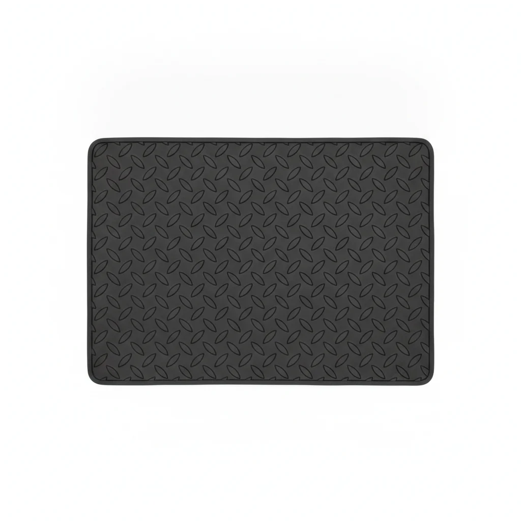
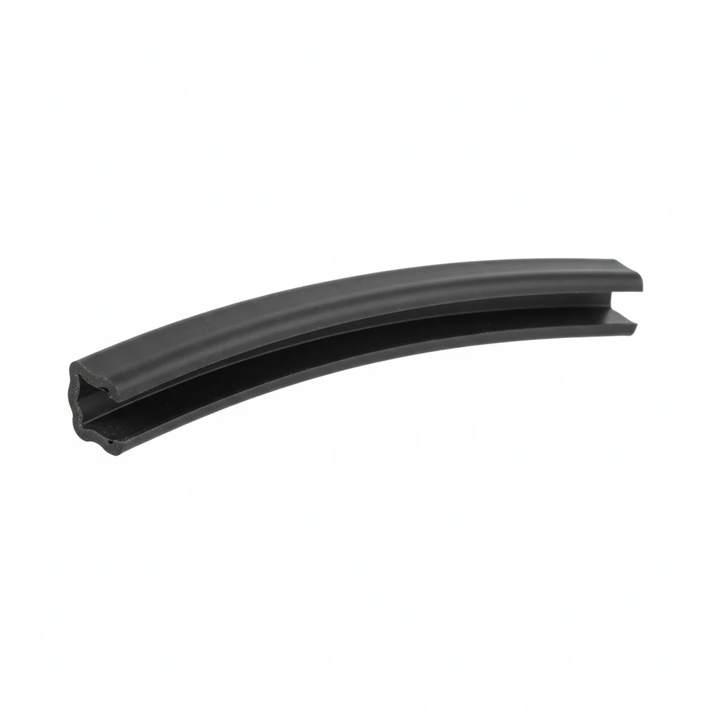
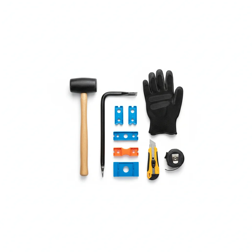
| Diamond Rubber Plate | Cold-Bonding Adhesive | Surface Treatment Agent | Edge Sealing Strip | Installation Tool Kit | |
|---|---|---|---|---|---|
| SPEC | Thickness 10-15mm, NR 60A diamond pattern | Two-component neoprene, initial adhesion ≥2N/mm | Metal primer + rubber topcoat, enhances adhesion | EPDM weather-resistant rubber, prevents moisture ingress | Pressure roller + scraper + heat gun |
| MATERIAL | NR | — | — | EPDM Rubber | — |
| GRADE | — | — | — | — | — |
| FINISH | HDG >=55um per ISO 1461 | HDG >=55um per ISO 1461 | HDG >=55um per ISO 1461 | HDG >=55um per ISO 1461 | HDG >=55um per ISO 1461 |
| CORROSION | C3 (ISO 12944-2) | C3 (ISO 12944-2) | C3 (ISO 12944-2) | Not applicable (polymer) | C3 (ISO 12944-2) |
| TEMP | -20°C to +80°C | -20°C to +80°C | -20°C to +80°C | -20°C to +80°C | -20°C to +80°C |
| WEIGHT | ~0.5 kg/piece | ~0.5 kg/piece | ~0.5 kg/piece | ~0.5 kg/piece | ~0.5 kg/piece |
| MOQ | 100 pcs | 100 pcs | 100 pcs | 100 pcs | 100 pcs |
| PACK | VCI paper + carton | VCI paper + carton | VCI paper + carton | VCI paper + carton | VCI paper + carton |
| STD | ISO 898-1, GB/T 3098.1 | ISO 898-1, GB/T 3098.1 | ISO 898-1, GB/T 3098.1 | ISO 898-1, GB/T 3098.1 | ISO 898-1, GB/T 3098.1 |
| USE | NR 60A diamond pattern | Initial adhesion ≥2N/mm | Enhances adhesion | Prevents moisture ingress | Installation tool kit |
PROCEDURE
- Degrease the pulley shell with isopropyl alcohol and abrade to a surface profile of at least 50 µm Ra, then wipe off dust with a lint-free cloth.
- Mix the two-component neoprene adhesive and apply a uniform coat to both the shell and the back of the NR 60A diamond plate; allow to become tacky.
- Align the diamond plate edges to within 1 mm over the full width, then press with a pressure roller from center outward to expel trapped air.
- Seal all perimeter joints with the EPDM edge sealing strip and heat-seal the ends with a heat gun to prevent moisture ingress.
- Allow the bond to cure for at least 24 hours at 15–35°C before applying belt tension.
COMMON ERRORS
| ✕ WRONG | CONSEQUENCE | ✓ CORRECT |
|---|---|---|
| Applying adhesive to an oily or rusty pulley shell without grit-blasting to Sa2.5 | Bond strength drops below 2 N/mm, the plate peels at the edge, and belt slippage starts within weeks. | Grit-blast the shell to Sa2.5 and verify cleanliness with a white cloth test before coating. |
| Curing the adhesive at low temperature or high humidity | The adhesive remains soft, initial adhesion never reaches 2 N/mm, and the lagging lifts under load. | Keep the work area at 15–35°C and below 70% RH for the full 24-hour cure. |
| Leaving the plate edges unsealed in a dusty environment | Abrasive fines work into the bond line and cause local detachment that exposes countersunk bolt heads. | Always fit the EPDM edge sealing strip and press it firmly into the adhesive. |
MAINTENANCE
Measure remaining lagging thickness monthly and record the wear curve; replace the diamond plate when thickness drops below 3 mm. Check edge sealing strips each shift for lifting, and re-bond any loose edges immediately.
Plan B · Polyurethane Heavy-Duty Lagging
C4 Harsh per ISO 12944-2
| Herringbone PU Plate | High-Strength Adhesive | Ceramic Inlay Strip | Quick-Release Lagging Sleeve | Online Thickness Gauge | |
|---|---|---|---|---|---|
| SPEC | Thickness 15-20mm, PU 80A herringbone groove | Polyurethane-specific adhesive, shear strength ≥8MPa | Al2O3 ceramic tiles embedded in PU matrix, local wear enhancement | Split design, replaceable without removing the roller | Ultrasonic probe, real-time monitoring of remaining lagging thickness |
| MATERIAL | PU | Polyurethane | PU | — | — |
| GRADE | — | — | — | — | — |
| FINISH | HDG >=55um per ISO 1461 | HDG >=55um per ISO 1461 | HDG >=55um per ISO 1461 | HDG >=55um per ISO 1461 | HDG >=55um per ISO 1461 |
| CORROSION | C3 (ISO 12944-2) | C3 (ISO 12944-2) | C3 (ISO 12944-2) | C3 (ISO 12944-2) | C3 (ISO 12944-2) |
| TEMP | -20°C to +80°C | -20°C to +80°C | -20°C to +80°C | -20°C to +80°C | -20°C to +80°C |
| WEIGHT | ~0.5 kg/piece | ~0.5 kg/piece | ~0.5 kg/piece | ~0.5 kg/piece | ~0.5 kg/piece |
| MOQ | 100 pcs | 100 pcs | 100 pcs | 100 pcs | 100 pcs |
| PACK | VCI paper + carton | VCI paper + carton | VCI paper + carton | VCI paper + carton | VCI paper + carton |
| STD | ISO 898-1, GB/T 3098.1 | ISO 898-1, GB/T 3098.1 | ISO 898-1, GB/T 3098.1 | ISO 898-1, GB/T 3098.1 | ISO 898-1, GB/T 3098.1 |
| USE | PU 80A herringbone groove | Shear strength ≥8MPa | Local wear enhancement | Replaceable without removing the roller | Real-time monitoring of remaining lagging thickness |
PROCEDURE
- Degrease the pulley shell with acetone to remove oil and moisture; verify surface roughness Ra < 3.2 µm for proper PU adhesive bonding.
- Apply the polyurethane-specific adhesive (shear strength ≥8 MPa) evenly to both the shell and the herringbone PU plate; allow tack-free time as per manufacturer.
- Position the herringbone PU plate (thickness 15-20 mm) onto the pulley, ensuring groove alignment with belt travel direction.
- Use a pressure roller to expel trapped air and achieve full contact; maintain pressure until adhesive sets.
- For quick-release sleeves, align the split ends and secure with the provided locking mechanism; verify the sleeve is fully seated.
- After curing, check for edge lifting and measure adhesion with a pull test on a sample area.
COMMON ERRORS
| ✕ WRONG | CONSEQUENCE | ✓ CORRECT |
|---|---|---|
| Using natural rubber adhesive with PU plate | Adhesive fails to bond PU, causing plate detachment under high tension and wet conditions. | Use polyurethane-specific adhesive with shear strength ≥8 MPa as specified. |
| Ignoring moisture on the pulley surface | Water film prevents adhesive bonding, leading to premature lagging separation and belt slippage. | Degrease and dry the surface thoroughly; verify no moisture before adhesive application. |
| Misaligning herringbone grooves against belt direction | Reduced water evacuation and increased slippage, accelerating wear and belt damage. | Align grooves to channel water away from the belt contact area per design. |
MAINTENANCE
Inspect lagging thickness using the online ultrasonic gauge at each planned maintenance window; replace when remaining thickness approaches the critical 3 mm threshold. Check herringbone grooves for clogging with sticky material and clean as needed. Verify adhesive integrity by tapping test for hollow sounds; schedule re-bonding if delamination is detected.
Plan C · Ceramic Composite Extreme Lagging
C5-M Extreme per ISO 12944-2
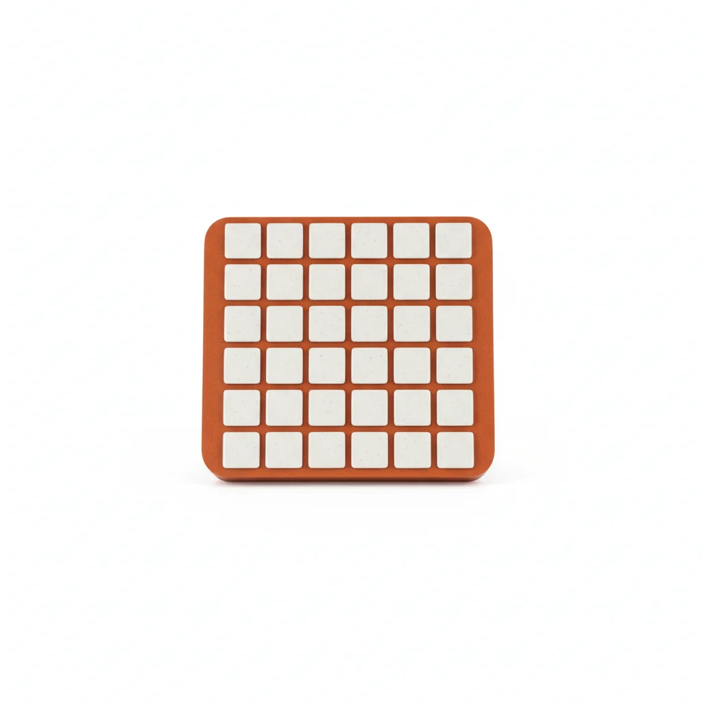
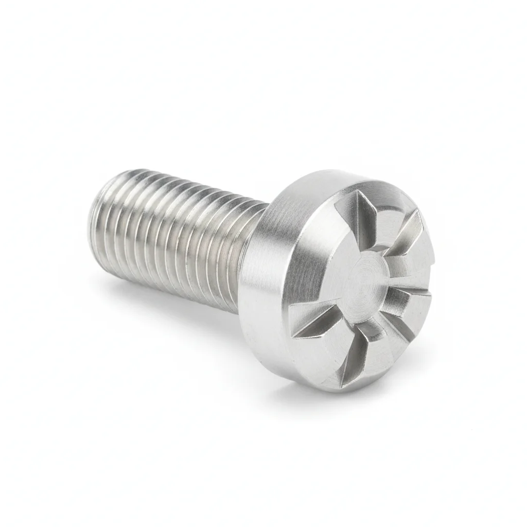
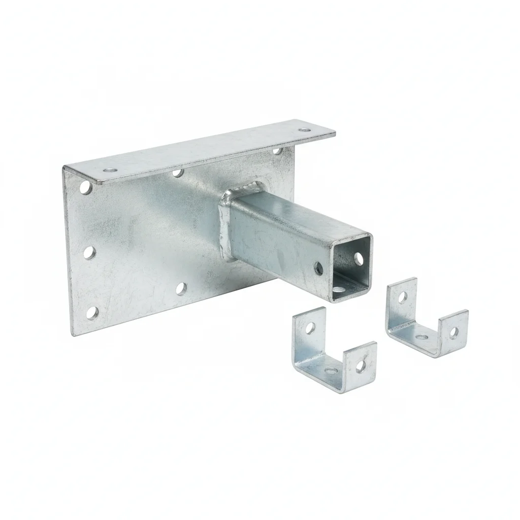
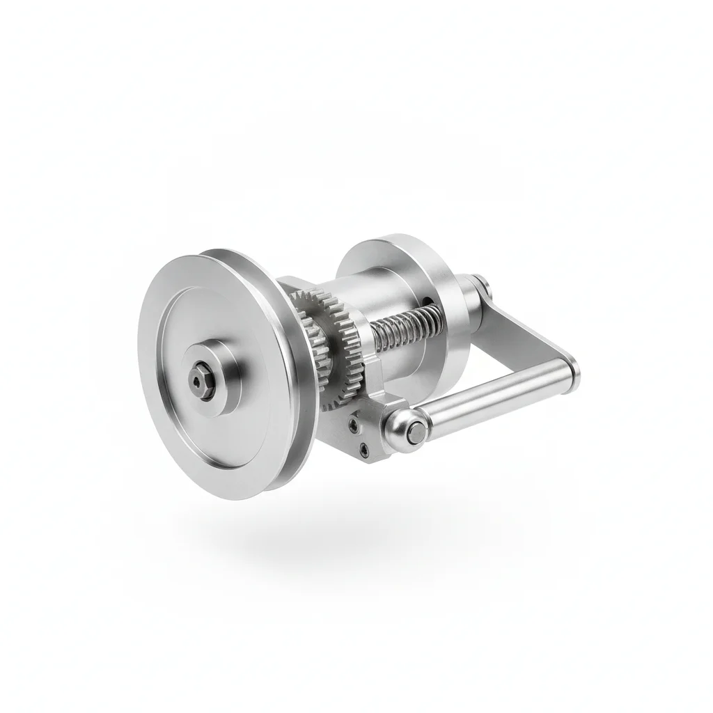
| Full Ceramic Lagging Module | Special Alloy Bolt | Modular Mounting Base | Smart Wear Monitoring | Automatic Tension Compensation | |
|---|---|---|---|---|---|
| SPEC | Thickness 20-25mm, Al2O3 ceramic tiles + temperature-resistant PU | M16×60, Inconel 625 corrosion and high temperature resistant | NM400 wear-resistant steel frame, segmented for easy partial replacement | Embedded sensor, real-time feedback on friction coefficient changes | Hydraulic system, maintains constant lagging pressure |
| MATERIAL | PU | — | — | HDG Steel | — |
| GRADE | — | — | — | — | — |
| FINISH | HDG >=55um per ISO 1461 | HDG >=55um per ISO 1461 | HDG >=55um per ISO 1461 | HDG >=55um per ISO 1461 | HDG >=55um per ISO 1461 |
| CORROSION | C3 (ISO 12944-2) | C3 (ISO 12944-2) | C3 (ISO 12944-2) | C3 (ISO 12944-2) | C3 (ISO 12944-2) |
| TEMP | -20°C to +80°C | -20°C to +80°C | -20°C to +80°C | -20°C to +80°C | -20°C to +80°C |
| WEIGHT | ~0.5 kg/piece | ~0.5 kg/piece | ~0.5 kg/piece | ~0.5 kg/piece | ~0.5 kg/piece |
| MOQ | 100 pcs | 100 pcs | 100 pcs | 100 pcs | 100 pcs |
| PACK | VCI paper + carton | VCI paper + carton | VCI paper + carton | VCI paper + carton | VCI paper + carton |
| STD | ISO 898-1, GB/T 3098.1 | ISO 898-1, GB/T 3098.1 | ISO 898-1, GB/T 3098.1 | ISO 898-1, GB/T 3098.1 | ISO 898-1, GB/T 3098.1 |
| USE | Al2O3 ceramic tiles + temperature-resistant PU | Inconel 625 corrosion and high temperature resistant | Segmented for easy partial replacement | Real-time feedback on friction coefficient changes | Maintains constant lagging pressure |
PROCEDURE
- Prepare the pulley shell by grit blasting to achieve a clean, rough surface (Ra < 1.6 µm) and remove all contaminants.
- Apply the high-temperature-resistant adhesive to the modular mounting base and the ceramic module back; ensure even coverage.
- Mount the full ceramic lagging module (20-25 mm thick) onto the base, aligning the Al2O3 tiles for continuous coverage.
- Secure each module with the special alloy bolts (M16×60, Inconel 625) through the pre-drilled holes; tighten to the specified torque in a cross pattern.
- Install the smart wear monitoring sensors and connect to the central system; verify real-time data transmission.
- After all modules are fixed, check the surface for any protruding bolt heads and grind if necessary to avoid belt damage.
COMMON ERRORS
| ✕ WRONG | CONSEQUENCE | ✓ CORRECT |
|---|---|---|
| Using standard carbon steel bolts instead of Inconel 625 | Bolts corrode and weaken at high temperatures, leading to module loosening and catastrophic lagging failure. | Use special alloy bolts (Inconel 625) as specified for corrosion and heat resistance. |
| Over-tightening bolts without torque control | Ceramic tiles crack under excessive stress, reducing friction surface integrity and causing premature wear. | Use a calibrated torque wrench and follow the specified tightening sequence to avoid over-stressing. |
| Skipping the smart wear sensor installation | No early warning of wear, leading to unplanned downtime and potential belt damage if lagging fails. | Install smart wear monitoring sensors to track friction coefficient changes in real time. |
MAINTENANCE
Continuously monitor the smart wear system for friction coefficient changes; schedule replacement when remaining thickness is near 3 mm. Inspect bolt torque on the modular mounting base at each overhaul window; re-torque any loose bolts to specification. Check ceramic tiles for cracks or dislodgement; replace damaged modules promptly to maintain full surface coverage.
REFERENCED STANDARDS
Technical Basis and Reference Standards
Belt Conveyors
Mining Product Safety MarkContinuous handling equipment and systems - Design rules for belt conveyors
Belt ConveyorTechnical Conditions for Belt Conveyors for Coal Mines
Conveyor Belt RollerTextile Fabric Core Conveyor Belts for General Use
Conveyor BeltStandard Test Method for Rubber Property—Durometer Hardness
SUPPLIER CAPABILITY
Quality, Delivery & Customization
Quality Control
- ✓MTC material certificates with every batch
- ✓Key parts sampled for hardness/salt spray/torque coefficient
- ✓100% inspection or AQL sampling before shipment
Delivery
- ✓Standard parts made to order: 7-15 days
- ✓Custom parts: 25-45 days
- ✓FOB/CIF/DDP supported
Customization
- ✓Drawing review and material matching
- ✓Non-standard sizes/heads/threads
- ✓Small-batch prototyping supported
Certification
- ✓Material certificates (MTC)
- ✓Spectrographic analysis reports
- ✓Salt spray test reports (on request)
MOQ: No MOQ for standard parts; custom parts assessed by process complexity
FAQ
Frequently Asked Questions
RELATED READING
Keep Reading & Next Step
BEYOND TECHNICAL SPECS
Finding the right factory, controlling quality, delivering on time — that's the real challenge. We cover fasteners, rubber, plastics, industrial textiles. One team, end to end.
SEE CAPABILITIES →