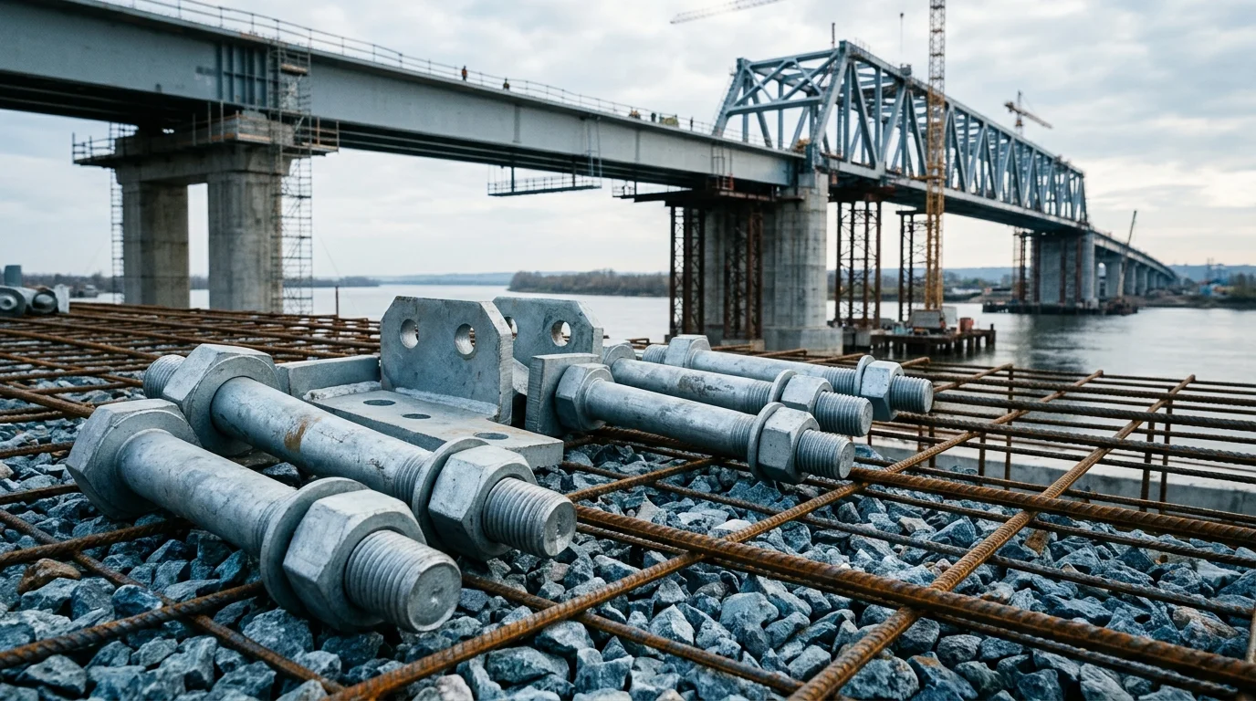
Luminaire Mount Brackets: Compare Materials, Coatings, and Load Ratings
For light (≤50kg), medium (50-150kg), and heavy (>150kg) luminaires, three bracket solutions are available: Q235B hot-dip galvanized, 304 stainless steel, and 6061-T6 aluminum alloy. Each has distinct load limits, corrosion resistance, and fastener requirements. This page helps engineers and procurement select the right hardware to avoid bracket failure and falling hazards
FIELD-SPECIFIC INSIGHT
Critical Checks for Bracket Fastener Selection
Bracket failure often originates from fastener corrosion or insufficient load rating. The three plans use different materials and coatings, but common pitfalls include mixing material grades and ignoring galvanic corrosion. Use this checklist to verify your procurement specs
WHAT TO CHECK
- 1Verify bolt grade: Plan A uses Grade 8.8 Dacromet, Plan B uses A2-70 stainless steel, Plan C uses 7075-T6 aluminum alloy. Mixing grades can cause unexpected failure
- 2Plan B relies on stainless steel passivation; Plan C uses anodized aluminum. Ensure coating matches environmental corrosivity category (C3, C4, C5-M per ISO 12944-2)
- 3Prevent galvanic corrosion: When aluminum brackets (Plan C) are paired with stainless steel bolts, use insulating washers or anti-corrosion grease to avoid accelerated corrosion
- 4Torque control: Plan C requires hydraulic torque wrench with ±3% preload accuracy. For Plans A and B, re-torque if tension loss exceeds 15% of specified torque
| Check | Why it matters | What to specify |
|---|---|---|
| Bolt material & grade | Incorrect grade reduces load capacity and may cause brittle fracture | Specify exact grade (e. G. , Grade 8.8, A2-70, 7075-T6) per plan |
| Coating thickness & standard | Insufficient coating leads to early corrosion and load loss | For stainless steel, verify passivation |
| Galvanic isolation | Dissimilar metals cause accelerated corrosion at joints | Use insulating washers or anti-seize grease between aluminum and steel |
| Torque specification | Under-torque causes loosening; over-torque damages threads | Specify torque value and re-torque interval per maintenance plan |
All load capacities and corrosion categories are based on the three plans provided. For site-specific conditions, consult structural engineer
Evidence level: source-page-only
INDUSTRY TECH REFERENCE
Four Luminaire-Bracket Kits: Fastener Specs, Seals and Failure Modes
Luminaire mounts are not one-size parts: floodlights, in-ground lights, underwater lights and wall washers differ in bolt size, sealing and how they fail. Match the table by luminaire type, then spec and accept against it.
| Luminaire type | Fastener / fixing | Sealing and material points | Failure and acceptance |
|---|---|---|---|
| Floodlight bracket | U-bracket, M8-M10 clamping bolts on both sides | Material by outdoor duty | Frequent re-aiming wears the bolt holes → the angle no longer locks |
| In-ground light | Face-ring bolts M6-M8 | 316L — ground water carries de-icing chloride (Cl⁻), which 304 cannot handle; EPDM washer keeps ground water out | Glass panel checked to the GB 50009 pedestrian live load of 2.0 kN/m²; the silicone under the panel must stay elastically deformable |
| Underwater light | All-316L fasteners + double O-rings | IP68 gland; torque and seal compression sized to the water depth (about 0.01 MPa per metre) | Under-compressed seal → water ingress, total loss |
| Wall washer / linear light | Aluminum housing + stainless-steel clips | EPDM gasket at every aluminum/stainless contact to stop galvanic corrosion | Fixing spacing over 500 mm → wind-induced micro-bending → LED solder-joint fatigue |
The 2.0 kN/m² pedestrian live load follows GB 50009-2012, Load code for the design of building structures; the ~0.01 MPa per metre of water depth is a physics-conversion magnitude estimate.
INDUSTRY TECH REFERENCE
The Angle-Won't-Hold Chain: Repeated Aiming Wears Out the Bolt Holes
Floodlights get re-aimed again and again — and the trouble usually shows up after the third or fourth adjustment, not because the bolt has loosened but because the hole has worn bigger. The chain starts with every adjustment.
- 1A U-bracket clamps the floodlight with M8-M10 bolts on both sides; to cover different targets, maintenance personnel slacken the bolts and change the elevation and azimuth angle
- 2Each re-aim squeezes the bolt shank against the hole wall with micro-slip — repeated operation slowly enlarges the hole diameter
- 3Once the hole is worn to the point where clamping force can no longer resist wind load, the bracket will not hold its angle: the luminaire drifts under gusts, the beam pattern wanders, and in the worst case the bracket sheds
- 4Interception: after every re-aim, re-tighten against the angle mark and re-check; if the angle will not lock, replace the bracket or step up the bolt size — do not prop it up with shims
- 5Inspection basis: for luminaires that get re-aimed often, add "angle locked state" to the periodic check, together with verifying the M8-M10 size
No magnitude-estimate figures are used.
INDUSTRY TECH REFERENCE
Two Ground-Level Specs for In-Ground Lights: De-Icing Chloride and 2.0 kN/m² Pedestrian Load
The in-ground light is the only luminaire that sits directly underfoot: it must survive de-icing salt in ground water and pedestrian traffic. Both specs land on its fasteners and its face panel.
- Face-ring bolts M6-M8 in 316L: ground water carries de-icing chloride (Cl⁻), and 304 pits under it — the same material line as the 304/316L tier for cable fixings in the archive
- An EPDM washer keeps ground water from seeping through the bolt holes into the lamp cavity: a missing or aged washer is the first entry point for internal corrosion
- The glass panel is checked to the GB 50009 pedestrian live load of 2.0 kN/m²; the silicone under the panel must keep its elastic deformability — once the compound hardens and is not replaced, the load transfers straight into the lamp cavity
- Procurement / acceptance basis: verify the 316L material certificate and M6-M8 size, and that the EPDM washer is in place — de-icing-salt projects do not accept 304
The 2.0 kN/m² pedestrian live load follows GB 50009-2012, Load code for the design of building structures. No magnitude-estimate figures are used.
INDUSTRY TECH REFERENCE
Underwater-Light Sealing Specs: 316L Throughout, Double O-Rings, Depth-Sized Torque
An underwater light gets no second chance on sealing: too little seal compression or a material that cannot resist corrosion, and one rework is a total lamp-out. Every spec is sized against the water depth.
- Material: all underwater-light fasteners are 316L (including around the O-ring seats), sealed by double O-rings — there is no seat for 304 underwater
- Pressure basis: about 0.01 MPa per metre of depth (physics conversion) — bolt torque and seal compression are sized to the actual water depth, not simply tightened to maximum preload
- Cable entry: an IP68 metal gland, one cable per opening; plastic glands are not in the underwater selection
- Acceptance / re-check: verify even O-ring compression and no permanent set — under-compression lets water straight in, and rework costs far more than the seal itself
The ~0.01 MPa per metre of water depth is a physics-conversion magnitude estimate; the IP68 rating follows IEC 60529, Degrees of protection provided by enclosures (IP code).
INDUSTRY TECH REFERENCE
Wall-Washer Fixing Spacing and Galvanic Isolation: Two Baselines for Stainless Clips
The fixings on wall washers and linear lights look trivial, but spacing and gaskets each prevent a distinct failure: spacing governs wind-induced solder fatigue, gaskets govern galvanic corrosion of the aluminum housing.
- Fixing spacing ≤ 500 mm: stainless-steel clips hold the aluminum housing; past that spacing, wind makes the housing micro-bend and the LED solder joints fatigue first — not the chips, the joints
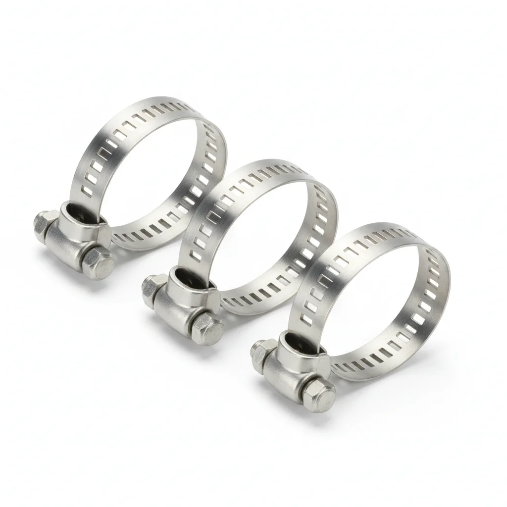
- Galvanic isolation: every aluminum/stainless contact must carry an EPDM gasket to stop galvanic corrosion — the same rule applies to an aluminum bracket paired with stainless-steel bolts
- Procurement / acceptance: verify the clips are stainless steel and the EPDM gaskets are in place; spot-check fixing spacing ≤ 500 mm after installation
No magnitude-estimate figures are used.
PLAN COMPARISON
Three-Plan Core Parameter Comparison
Compare row by row. Click column headers to jump to plan details.
| A · Plan A · Q235B Standard Luminaire Bracket | B · Plan B · 304 Stainless Steel Heavy-Duty Luminaire Bracket | C · Plan C · 6061 Aluminum Alloy Extreme Luminaire Bracket | |
|---|---|---|---|
| 1. SINGLE-ARM BRACKET | |||
| SPEC | Arm length 1.5m, Q235B welded + hot-dip galvanized, load capacity ≤50kg | Arm length 2.0m, 304 stainless steel forged, load capacity ≤150kg | Arm length 3.0m, 6061-T6 extruded, load capacity ≤300kg |
| MATERIAL | Q235B | 304 Stainless Steel | 6061-T6 |
| FINISH | hot-dip galvanized ≥55μm per ISO 1461 | HDG >=55um per ISO 1461 | HDG >=55um per ISO 1461 |
| 2. HOOP CLAMP | |||
| SPEC | φ89-114mm adjustable, Q235B stamped + hot-dip galvanized | φ114-165mm adjustable, 304 stainless steel precision casting | φ165-219mm adjustable, Inconel 625 precision casting |
| MATERIAL | Q235B | 304 Stainless Steel | — |
| FINISH | HDG >=55um per ISO 1461 | HDG >=55um per ISO 1461 | HDG >=55um per ISO 1461 |
| 3. FIXING BOLT | |||
| SPEC | M12×80, Grade 8.8 Dacromet coating | M16×100, A2-70 Stainless Steel | M20×120, 7075-T6 Aluminum Alloy |
| MATERIAL | — | 70 Stainless Steel | Aluminum Alloy |
| GRADE | Grade 8.8 | A2-70 | — |
| FINISH | HDG >=55um per ISO 1461 | HDG >=55um per ISO 1461 | HDG >=55um per ISO 1461 |
| 4. ANTI-LOOSENING SHIM | |||
| SPEC | Nordlock wedge locking washer | M16, A2-70 + Nordlock washer | RFID chip, records installation time and inspection records |
| MATERIAL | — | — | EPDM Rubber |
| GRADE | — | A2-70 | — |
| FINISH | HDG >=55um per ISO 1461 | HDG >=55um per ISO 1461 | HDG >=55um per ISO 1461 |
| 5. ANTI-CORROSION GREASE | |||
| SPEC | Lithium grease NLGI-2, apply to connection surfaces to prevent seizing | Epoxy zinc-rich primer + polyurethane topcoat, salt spray resistance 1000h | Hydraulic torque wrench, preload controllable ±3% |
| MATERIAL | — | Polyurethane | — |
| FINISH | HDG >=55um per ISO 1461 | HDG >=55um per ISO 1461 | HDG >=55um per ISO 1461 |
SELECTION GUIDE
How to choose a bracket solution based on luminaire weight?
| Operating condition | Recommended option | Key basis |
|---|---|---|
| Light luminaire (≤50kg), general landscape | Plan A: Q235B standard bracket — single-arm 1.5m (load ≤50kg) + hoop clamp φ89-114mm + fixing bolt M12×80 Grade 8.8 Dacromet + Nordlock anti-loosening washer | C3 (ISO 12944-2) general landscape; lowest cost |
| Medium luminaire (50-150kg) / coastal high-humidity | Plan B: 304 SS heavy-duty bracket — double-arm 2.0m (load ≤150kg) + reinforced hoop φ114-165mm precision cast + fixing bolt M16×100 A2-70 + A2-70 founder Nordlock lock nut | C4 harsh (ISO 12944-2) coastal splash zones; corrosion resistant, long life |
| Heavy luminaire (>150kg) / typhoon zone / ultra-long life | Plan C: 6061-T6 aluminum extreme bracket — multi-arm 3.0m (load ≤300kg) + Inconel 625 hoop φ165-219mm + special alloy bolt M20×120 7075-T6; hydraulic torque wrench ±3% preload | C5-M extreme (ISO 12944-2); lightweight high strength; precise preload control |
| Chlorine-containing wet environment (stress-corrosion risk) | Use 316 stainless steel bracket (load ≥180kg) instead of 304 | 304 stainless steel may suffer stress corrosion in chlorine environments, reducing load capacity by 20% |
| Galvanic-corrosion risk between dissimilar metals | When aluminum bracket (Plan C) is paired with stainless steel bolts, use insulating washers or anti-corrosion grease | Dissimilar-metal contact accelerates corrosion at joints; also re-torque if tension loss exceeds 15% of specified torque |
Plan A · Q235B Standard Luminaire Bracket
C3 (ISO 12944-2) for general landscape environments.
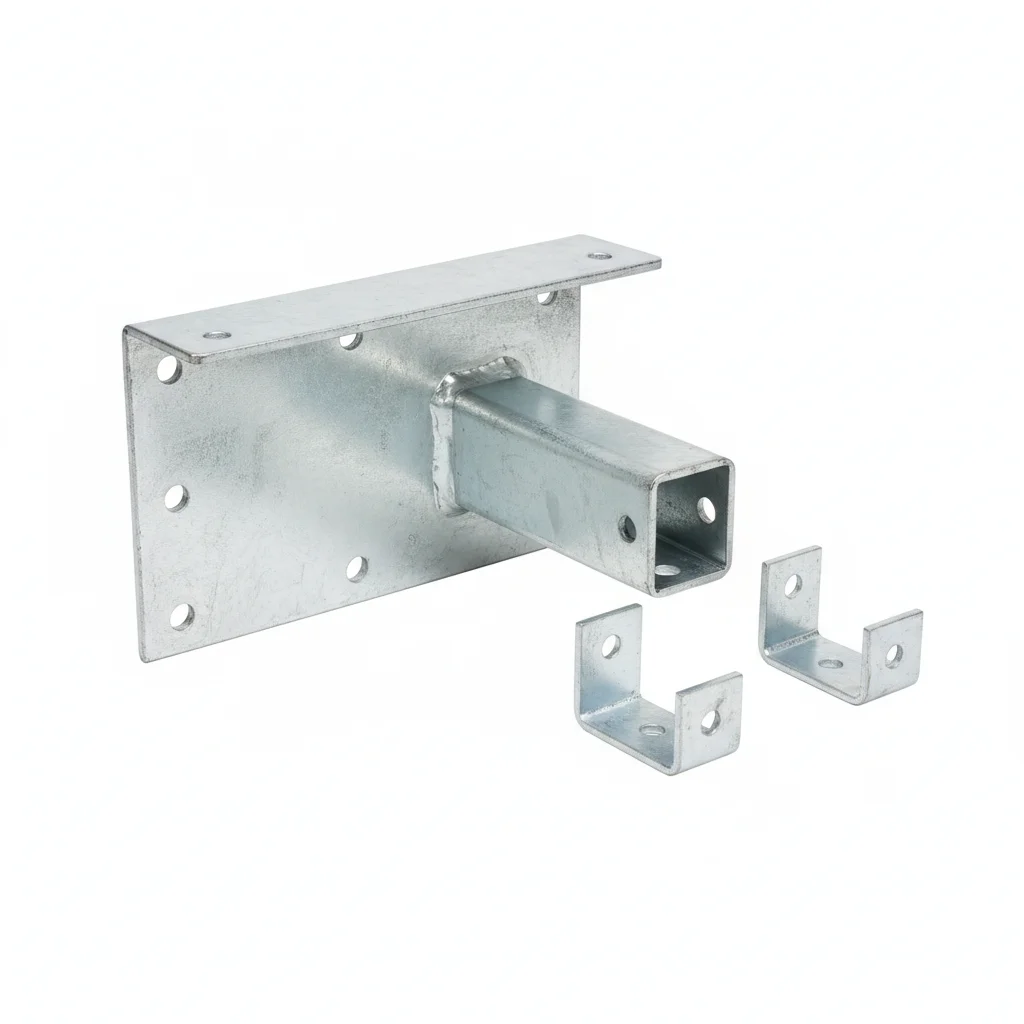
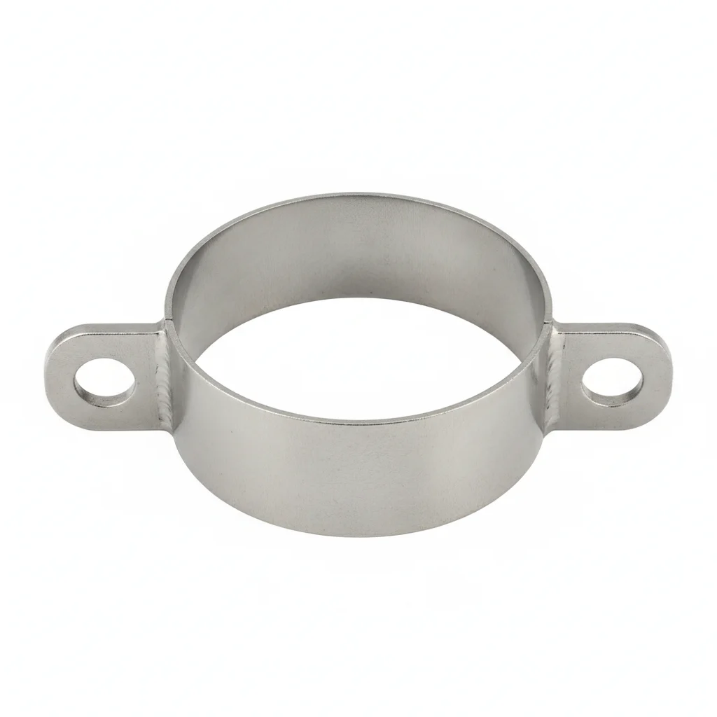
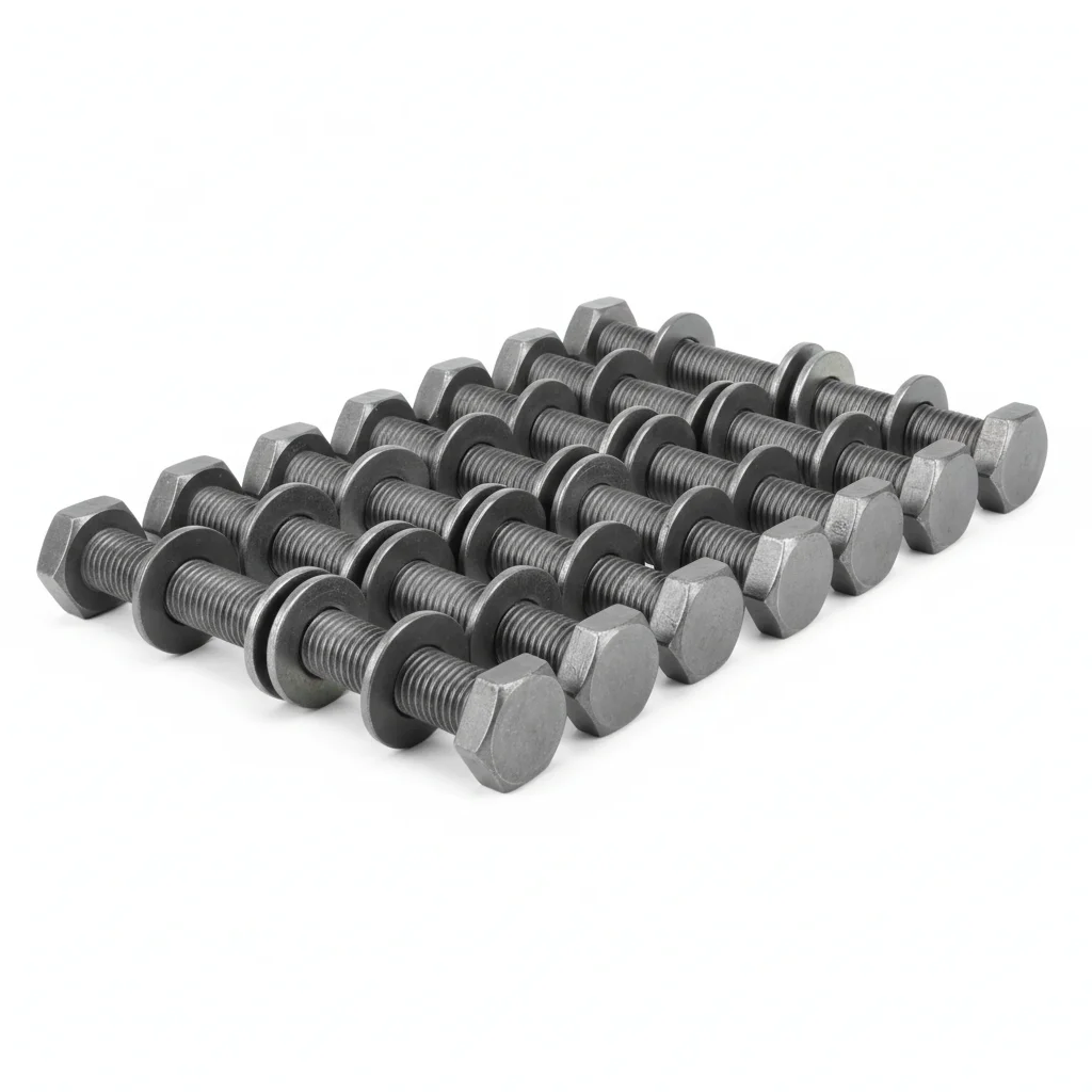
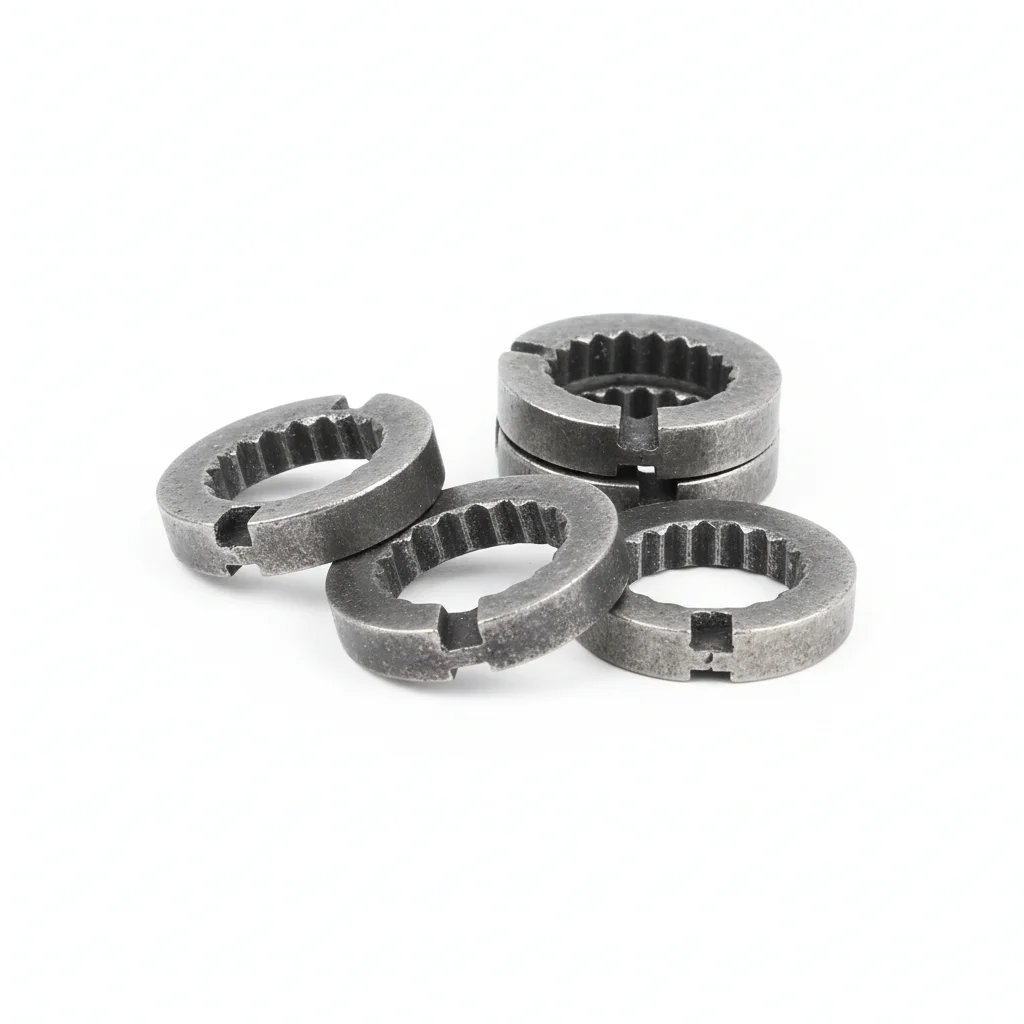
| Single-Arm Bracket | Hoop Clamp | Fixing Bolt | Anti-Loosening Shim | Anti-Corrosion Grease | |
|---|---|---|---|---|---|
| SPEC | Arm length 1.5m, Q235B welded + hot-dip galvanized, load capacity ≤50kg | φ89-114mm adjustable, Q235B stamped + hot-dip galvanized | M12×80, Grade 8.8 Dacromet coating | Nordlock wedge locking washer | Lithium grease NLGI-2, apply to connection surfaces to prevent seizing |
| MATERIAL | Q235B | Q235B | — | — | — |
| GRADE | — | — | Grade 8.8 | — | — |
| FINISH | hot-dip galvanized ≥55μm per ISO 1461 | HDG >=55um per ISO 1461 | HDG >=55um per ISO 1461 | HDG >=55um per ISO 1461 | HDG >=55um per ISO 1461 |
| CORROSION | C3 (ISO 12944-2) | C3 (ISO 12944-2) | C3 (ISO 12944-2) | C3 (ISO 12944-2) | C3 (ISO 12944-2) |
| TEMP | -20°C to +80°C | -20°C to +80°C | -20°C to +80°C | -20°C to +80°C | -20°C to +80°C |
| WEIGHT | ~0.5 kg/piece | ~0.5 kg/piece | ~0.5 kg/piece | ~0.5 kg/piece | ~0.5 kg/piece |
| MOQ | 100 pcs | 100 pcs | 100 pcs | 100 pcs | 100 pcs |
| PACK | VCI paper + carton | VCI paper + carton | VCI paper + carton | VCI paper + carton | VCI paper + carton |
| STD | ISO 898-1, GB/T 3098.1 | ISO 898-1, GB/T 3098.1 | ISO 898-1, GB/T 3098.1 | ISO 898-1, GB/T 3098.1 | ISO 898-1, GB/T 3098.1 |
| USE | Load capacity ≤50kg | Q235B stamped + hot-dip galvanized | Grade 8.8 Dacromet coating | Anti-loosening shim | Apply to connection surfaces to prevent seizing |
PROCEDURE
- Clean the pole and bracket contact faces with isopropyl alcohol, then check surface flatness against a straightedge.
- Lift the luminaire bracket into position and secure it with the hoop clamp, ensuring the clamp is centered on the pole.
- Insert the M12×80 Grade 8.8 Dacromet bolts through the bracket flange and tighten them by hand until snug.
- Tighten the bolts in a star pattern using a calibrated torque wrench; the final torque should be per the design specification for Grade 8.8 bolts.
- Fit the Nordlock anti-loosening shims under the nut or bolt head as specified, then re-check torque on a sample of fasteners.
- Apply a thin coat of lithium grease (NLGI-2) to exposed threads and contact surfaces to prevent seizing during service.
COMMON ERRORS
| ✕ WRONG | CONSEQUENCE | ✓ CORRECT |
|---|---|---|
| Using ordinary bolts instead of Grade 8.8 Dacromet-coated fasteners. | Lower-grade bolts can yield or fracture under the luminaire load, risking bracket failure. | Verify bolts are marked Grade 8.8 and have the specified Dacromet coating before installation. |
| Tightening the hoop clamp without first verifying the pole diameter is within the clamp's adjustable range. | An oversized or undersized clamp will not seat properly, leading to loose grip and potential bracket slippage. | Measure the pole diameter and confirm the hoop clamp's range (φ89-114mm) matches before assembly. |
MAINTENANCE
Inspect bracket and fasteners at least seasonally, especially before and after storm periods. Re-torque any bolts found loose, and check for corrosion on the galvanized coating. If surface rust appears in scratches, touch up with zinc-rich paint to maintain corrosion protection.
Plan B · 304 Stainless Steel Heavy-Duty Luminaire Bracket
C4 Harsh (ISO 12944-2) for coastal splash zones and high-humidity atmospheres
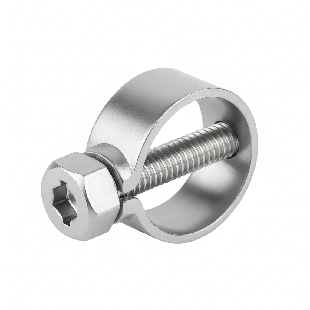
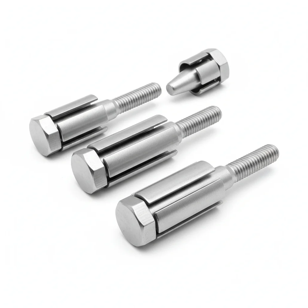
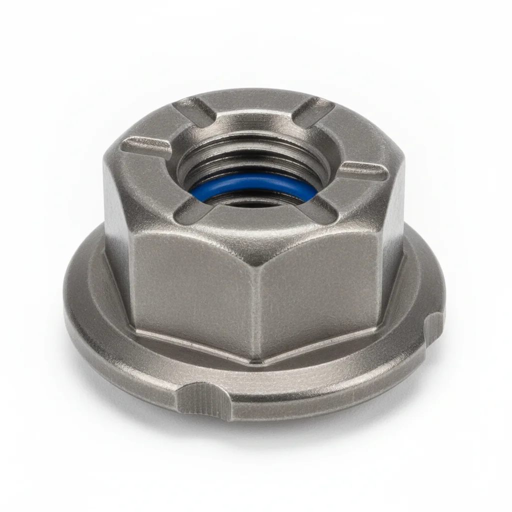
| Double-Arm Bracket | Reinforced Hoop Clamp | Fixing Bolt | Anti-Loosening Lock Nut | Anti-Corrosion Coating | |
|---|---|---|---|---|---|
| SPEC | Arm length 2.0m, 304 stainless steel forged, load capacity ≤150kg | φ114-165mm adjustable, 304 stainless steel precision casting | M16×100, A2-70 Stainless Steel | M16, A2-70 + Nordlock washer | Epoxy zinc-rich primer + polyurethane topcoat, salt spray resistance 1000h |
| MATERIAL | 304 Stainless Steel | 304 Stainless Steel | 70 Stainless Steel | — | Polyurethane |
| GRADE | — | — | A2-70 | A2-70 | — |
| FINISH | HDG >=55um per ISO 1461 | HDG >=55um per ISO 1461 | HDG >=55um per ISO 1461 | HDG >=55um per ISO 1461 | HDG >=55um per ISO 1461 |
| CORROSION | C3 (ISO 12944-2) | C3 (ISO 12944-2) | C3 (ISO 12944-2) | C3 (ISO 12944-2) | C3 (ISO 12944-2) |
| TEMP | -20°C to +80°C | -20°C to +80°C | -20°C to +80°C | -20°C to +80°C | -20°C to +80°C |
| WEIGHT | ~0.5 kg/piece | ~0.5 kg/piece | ~0.5 kg/piece | ~0.5 kg/piece | ~0.5 kg/piece |
| MOQ | 100 pcs | 100 pcs | 100 pcs | 100 pcs | 100 pcs |
| PACK | VCI paper + carton | VCI paper + carton | VCI paper + carton | VCI paper + carton | VCI paper + carton |
| STD | ISO 898-1, GB/T 3098.1 | ISO 898-1, GB/T 3098.1 | ISO 898-1, GB/T 3098.1 | ISO 898-1, GB/T 3098.1 | ISO 898-1, GB/T 3098.1 |
| USE | Load capacity ≤150kg | 304 stainless steel precision casting | A2-70 Stainless Steel | A2-70 + Nordlock washer | Salt spray resistance 1000h |
PROCEDURE
- Degrease the 304 forged bracket and M16 bolt threads with acetone; confirm the surface is free of chlorides and oils.
- Apply a lithium-based anti-seize compound rated for stainless steel to the M16×100 A2-70 bolt threads and contact faces.
- Position the double-arm bracket and reinforced hoop clamp (φ114–165mm) against the pole; hand-tighten the A2-70 lock nut with Nordlock washer.
- Tighten in a cross-pattern sequence to the specified torque using a calibrated wrench; verify 10% of joints with a torque auditor.
- Pull-test a 5% sample of M16 bolts to 80% of proof load; replace any bolt that slips or fails to hold.
- Apply the epoxy zinc-rich primer and polyurethane topcoat (salt spray 1000h) to exposed threads and any scratches from installation.
COMMON ERRORS
| ✕ WRONG | CONSEQUENCE | ✓ CORRECT |
|---|---|---|
| Mixing A2-70 bolts with carbon steel washers or nuts in the coastal environment | Galvanic corrosion at the contact surface can pit the stainless steel and reduce the bracket's load capacity over time. | Use only A2-70 stainless steel nuts and Nordlock washers; verify all components are marked A2-70 before assembly. |
| Over-tightening the M16 bolt beyond the specified torque to compensate for a loose fit | Strain-hardens the 304 stainless steel, increasing susceptibility to stress-corrosion cracking in chloride-laden coastal air. | Use a calibrated torque wrench and adhere to the torque value in the plan; if the joint still feels loose, add a shim rather than over-torquing. |
MAINTENANCE
Inspect stainless brackets and A2-70 bolts at each seasonal maintenance window (spring and autumn) and after any typhoon or storm event. Re-torque any bolt found below 80% of specified torque. Replace bolts showing pitting deeper than 0.3mm or corrosion covering more than 5% of the surface. Every 3 years, disassemble a 20% sample of the double-arm bracket joints to check for crevice corrosion; replace all A2-70 fasteners every 5 years regardless of appearance. Record all findings in the CMMS with inspector ID and corrective action.
Plan C · 6061 Aluminum Alloy Extreme Luminaire Bracket
C5-M Extreme (ISO 12944-2) for typhoon-prone offshore and industrial zones
| Multi-Arm Combined Bracket | Special Alloy Hoop Clamp | Special Alloy Bolt | Smart Monitoring Tag | Dedicated Installation Tool | |
|---|---|---|---|---|---|
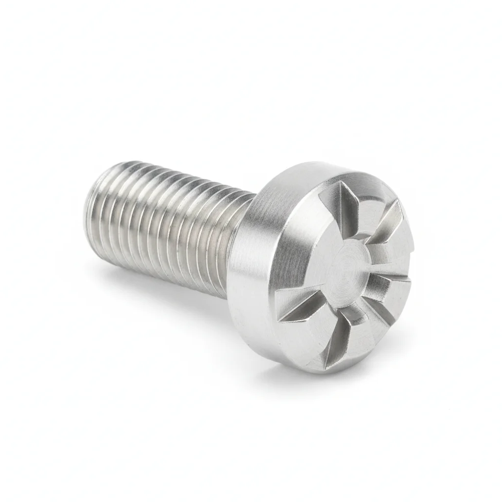
| SPEC | Arm length 3.0m, 6061-T6 extruded, load capacity ≤300kg | φ165-219mm adjustable, Inconel 625 precision casting | M20×120, 7075-T6 Aluminum Alloy | RFID chip, records installation time and inspection records | Hydraulic torque wrench, preload controllable ±3% |
| MATERIAL | 6061-T6 | — | Aluminum Alloy | EPDM Rubber | — |
| GRADE | — | — | — | — | — |
| FINISH | HDG >=55um per ISO 1461 | HDG >=55um per ISO 1461 | HDG >=55um per ISO 1461 | HDG >=55um per ISO 1461 | HDG >=55um per ISO 1461 |
| CORROSION | C3 (ISO 12944-2) | C3 (ISO 12944-2) | C3 (ISO 12944-2) | Not applicable (polymer) | C3 (ISO 12944-2) |
| TEMP | -20°C to +80°C | -20°C to +80°C | -20°C to +80°C | -20°C to +80°C | -20°C to +80°C |
| WEIGHT | ~0.5 kg/piece | ~0.5 kg/piece | ~0.5 kg/piece | ~0.5 kg/piece | ~0.5 kg/piece |
| MOQ | 100 pcs | 100 pcs | 100 pcs | 100 pcs | 100 pcs |
| PACK | VCI paper + carton | VCI paper + carton | VCI paper + carton | VCI paper + carton | VCI paper + carton |
| STD | ISO 898-1, GB/T 3098.1 | ISO 898-1, GB/T 3098.1 | ISO 898-1, GB/T 3098.1 | ISO 898-1, GB/T 3098.1 | ISO 898-1, GB/T 3098.1 |
| USE | Load capacity ≤300kg | Inconel 625 precision casting | 7075-T6 Aluminum Alloy | Records installation time and inspection records | Preload controllable ±3% |
PROCEDURE
- Degrease the 6061-T6 bracket flanges and 7075-T6 bolt threads with MEK; verify surface roughness Ra <1.6μm.
- Apply a marine-grade anti-seize compound rated for aluminum and Inconel to all threaded connections.
- Assemble the multi-arm bracket with the special alloy hoop clamp (φ165–219mm) and 7075-T6 M20×120 bolts; align within 0.3mm using a laser level.
- Tighten the M20 bolts with the dedicated hydraulic torque wrench (preload accuracy ±3%) in a cross-pattern sequence; verify preload on 10% of bolts using a tension indicator.
- Perform dye-penetrant NDT on 10% of the welded and forged joints; reject any bracket showing crack indications.
- Apply protective sealant to all exposed threads and install the RFID smart monitoring tag to record installation and inspection data.
COMMON ERRORS
| ✕ WRONG | CONSEQUENCE | ✓ CORRECT |
|---|---|---|
| Using standard steel bolts instead of the specified 7075-T6 aluminum alloy bolts | Galvanic corrosion between steel and aluminum will rapidly degrade the 6061-T6 bracket, leading to premature failure under typhoon loads. | Verify bolt material is 7075-T6 aluminum alloy before installation; use a PMI (positive material identification) tool on a 10% sample if material certificates are unavailable. |
| Ignoring the torque wrench calibration and using a manual wrench for the M20 bolts | Inconsistent preload can cause the bracket to loosen under wind-induced vibration, risking the luminaire falling. | Use the dedicated hydraulic torque wrench with ±3% accuracy; calibrate it before each installation and log the calibration certificate. |
MAINTENANCE
Inspect the 6061-T6 bracket and 7075-T6 bolts before each typhoon season (typically early summer) and after every typhoon event. Re-torque any bolt that has lost more than 15% of its specified preload. Replace bolts showing corrosion pitting deeper than 0.3mm or any crack indication from NDT. Every 3 years, disassemble a 20% sample of the multi-arm joints for dye-penetrant testing; replace all critical fasteners every 5 years regardless of condition. Update the RFID tag with inspection results and store in the CMMS with inspector ID and corrective actions.
REFERENCED STANDARDS
Technical Basis and Reference Standards
Road Lighting Poles
Floodlight Safety RequirementsTechnical Conditions and Test Methods for Solar Home Photovoltaic Power Systems
Luminaire Safety RequirementsLoad Code for Building Structures
General Safety Requirements for LuminairesMechanical Properties of Fasteners - Bolts, Screws and Studs
Aluminum Alloy SheetStandard Specification for Aluminum and Aluminum-Alloy Sheet and Plate
SUPPLIER CAPABILITY
Quality, Delivery & Customization
Quality Control
- ✓MTC material certificates with every batch
- ✓Key parts sampled for hardness/salt spray/torque coefficient
- ✓100% inspection or AQL sampling before shipment
Delivery
- ✓Standard parts made to order: 7-15 days
- ✓Custom parts: 25-45 days
- ✓FOB/CIF/DDP supported
Customization
- ✓Drawing review and material matching
- ✓Non-standard sizes/heads/threads
- ✓Small-batch prototyping supported
Certification
- ✓Material certificates (MTC)
- ✓Spectrographic analysis reports
- ✓Salt spray test reports (on request)
MOQ: No MOQ for standard parts; custom parts assessed by process complexity
FAQ
Frequently Asked Questions
RELATED READING
Keep Reading & Next Step
BEYOND TECHNICAL SPECS
Finding the right factory, controlling quality, delivering on time — that's the real challenge. We cover fasteners, rubber, plastics, industrial textiles. One team, end to end.
SEE CAPABILITIES →