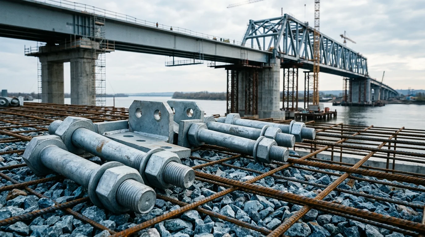
Light Pole Anchor Bolt Hardware: Prevent Base Plate Corrosion
Street-light and luminaire support failures often start at the concrete foundation interface: anchor bolts, nuts, washers, grout pocket, base plate drainage and coating damage around the pole base
FIELD-SPECIFIC INSIGHT
The Pole Is Only as Reliable as the Anchor Package
ASTM F1554 publicly frames anchor bolts as structural-support hardware for concrete foundations, including street lighting and traffic signals. AASHTO separately frames signs, luminaires and signals as structural supports. For procurement, the useful check is the whole base hardware package, not just the pole tube
WHAT TO CHECK
- 1Specify anchor bolts, nuts and washers as one package, not separate loose hardware lines
- 2Check whether grout, drainage and base-plate geometry can trap water around the anchor group
- 3Ask for coating and thread-protection details because installation damage often starts at exposed threads
- 4Require drawings that show anchor pattern, projection, washer stack and access for retightening or inspection
| Check | Why it matters | What to specify |
|---|---|---|
| Anchor package | A compliant pole can still fail if bolts, nuts and washers are mismatched | Anchor bolt standard, strength grade, nut and washer pairing, coating and thread class |
| Base drainage | Standing water at the base plate accelerates corrosion around threads and washers | Grout detail, drain path, base-plate gap and corrosion protection at the exposed hardware |
| Inspection access | Hidden nuts or buried threads make retightening and corrosion checks difficult | Anchor projection, cover detail and maintenance access around each fastener |
Use ASTM F1554 and AASHTO as scope references. Project loads, pole geometry and foundation design still come from the engineer of record
Evidence level: standard-backed
RISK AUDIT // ENGINEERING DIAGNOSIS
Procurement Pitfall Avoidance Guide
"Base-plate corrosion and anchor loosening are the usual hidden failure points behind a leaning pole."
QC-AUDIT // REV.5
SCALE 1:1 · 03 ITEMS
RISK-01
Light pole base flange deformed by frost heave in winter
Corrective Measures
RISK-02
Material corrosion leading to wind resistance performance degradation
Corrective Measures
RISK-03
Fatigue cracking in weld heat-affected zone under temperature cycling
Corrective Measures
INDUSTRY TECH REFERENCE
Three Numbers for Base Wind Check: Pressure, Moment and Bolt Margin
A landscape pole is a decorative member and a load-bearing one — each pole has its own shape, height and luminaire count, so its wind load is calculated individually and cannot be copied from a standard atlas. When a wind class becomes a procurement spec, start with these three numbers.
- Wind-load magnitude: an 8 m landscape pole with 3 floodlights + 2 wall washers + a basket ornament at the top has a wind area of about 0.8 m²; under a GB 50009 basic wind pressure of 0.45 kN/m² (coastal), wk ≈ μz·μs·w0 ≈ 0.59 kN/m², giving a base-flange bending moment of about 5-10 kN·m including gust factor
- Bolt loading: that moment puts roughly 20-40 kN on each M20 anchor bolt — far below the ~148 kN preload ceiling of a grade 8.8 bolt, so the wind bottleneck is usually not the bolt itself
- Direction basis: trees, buildings and sculptures reshape the local wind field, the leeward side is not always the least loaded, and corner vortices arrive from any angle — anchor bolts are therefore designed for equal strength around the full 360°, not for one prevailing direction
- Procurement mapping: a wind tier only sets the moment magnitude; on the order it still comes down to grade + embedment precision + grout quality — grade 8.8 base bolts, embedment position deviation ≤ 2 mm, verticality ≤ 1/100, and secondary grout ≥ 60 MPa at 28 days
The ~0.8 m² wind area, wk≈0.59 kN/m², base bending moment of 5-10 kN·m, per-bolt tension of 20-40 kN and the ~148 kN grade-8.8 preload ceiling are all magnitude estimates; the 0.45 kN/m² coastal basic wind pressure and the wind-load calculation follow GB 50009-2012, Load code for the design of building structures.
INDUSTRY TECH REFERENCE
The Frost-Heave Chain on a Pole: 9% Ice Expansion and a Worsening Spring Lean
In frozen-soil regions a pole is often not blown over by wind — it is pushed over by winter, with heave force acting directly on the foundation. The chain starts with freezing and ends with a leaning pole.
- 1Winter freezes the soil: frost-susceptible ground expands about 9% in volume when freezing, and local frost depth is 1.0-1.5 m (up to 2 m in the northeast)
- 2Heave force lifts the foundation; in spring thaw the bearing capacity drops and the foundation settles back — one freeze-thaw cycle is one lift-and-settle round
- 3Repeated cycling deforms the base flange under moments it was not designed for, and the pole leans; a leaning pole changes its effective wind area and load direction, worsening wind performance further
- 4Interception: embed the foundation at least 0.5 m below the local maximum frost depth, isolate the frost line with a sleeve, and use an enlarged footing base — keep heave force off the base and side walls
- 5Inspection rhythm: check pole verticality every spring after thaw (against the embedment acceptance basis of ≤ 1/100); when out of tolerance, check foundation and grout before correcting — do not replace bolts while leaving the foundation problem
The 1.0-1.5 m frost depth in northern regions (up to 2 m in the northeast) and the ~9% ice-expansion figure are magnitude estimates.
INDUSTRY TECH REFERENCE
The Pole-Base Trio: Anchor Cage, Grout and Seal — Specs for Each
A pole stands on its foundation through three steps in sequence — anchor-cage embedment, secondary grout pour and flange sealing. Each has verifiable numbers to check one by one at acceptance.
| Part | Key parameters and acceptance basis | Failure consequence |
|---|---|---|
| Anchor bolt cage | 4-8 L-shaped anchor bolts welded to a positioning template and cast as one cage; position deviation ≤ 2 mm, verticality ≤ 1/100 | Flange holes misalign and bolts take eccentric tension — fix with the template before pouring, monitor during the pour, and never re-drill oversize to force a fit |
| Secondary grout | Fill the 30-50 mm gap between flange and foundation top with high-strength non-shrink grout, ≥ 60 MPa at 28 days; ordinary cement mortar is not acceptable | Ordinary mortar shrinks and cracks within 3-5 years → rainwater gets in → bolts corrode → the pole is pulled out root and all in a strong wind |
| Flange seal | Apply silicone sealant to the joint between base flange and grout, reapply every 3-5 years | Trapped water keeps the flange and bolts wet long-term, so they corrode first — along with any exposed metal near the access door |
The 3-5 year cracking window for ordinary mortar and the 3-5 year resealing interval are service-life magnitude estimates.
INDUSTRY TECH REFERENCE
Segment Flange Bolts: Grade, Torque and the EPDM Gasket
Poles over 12 m — or limited by transport — are built in 2-3 segments, which makes the flange joint the pole's waist. Bolt grade, torque and the sealing gasket at that joint each have to be right, or trouble starts at the joint.
- Segmentation rule: poles over 12 m are joined in 2-3 flange segments — a scaled-down tower-flange joint, tightened to the low band of the design preload
- Specs: M16-M20, grade 8.8, hot-dip galvanized or 304 chosen by the environmental corrosion class; verify grade and material against head markings on arrival
- Torque: M20 grade 8.8 is tightened to 250-300 N·m (standard value about 300 N·m at μ=0.14), taking the low band for segment flanges — the old "200 for segments / 250 for bases" figures have been corrected
- Sealing: an EPDM gasket on the flange face keeps rainwater out of the shaft — wet cables mean leakage and whole-circuit tripping, so the seal matters as much as the torque for joint life
The M20 grade-8.8 torque of 250-300 N·m (standard value about 300 N·m at μ=0.14) is a magnitude estimate.
INDUSTRY TECH REFERENCE
Four References for Pole Selection and Acceptance: Design, Load, Galvanizing and Lightning
From specification to acceptance, a pole touches four standard families: design, loading, corrosion protection and lightning. Only numbers and scope are listed here for navigation — acceptance values must come from the current standard texts.
The listed standards are for navigation only, without reproducing clauses: CJJ 45 (urban road lighting design), GB 50009-2012 (load code, pedestrian live load 2.0 kN/m²), GB/T 13912-2020 (hot-dip galvanized coatings) and GB 50057 (lightning protection design). No magnitude-estimate figures are used.
INDUSTRY TECH REFERENCE
How Pole Hardware Is Bought: Project Batches, Front-Loaded Orders and Steady Spares
Pole hardware is not retail — who decides, when to order and how spares repeat each follow their own rules. Sort those out before asking for quotes.
Landscape pole hardware is bought project-wise: on new-build or retrofit projects the municipal lighting contractor orders in one batch, typically tens to hundreds of poles per project; anchor bolt cages must be procured ahead of the foundation works, and lightning-earthing parts are selected by the on-site soil condition. The urban lighting administration handles O&M spares, where consumables such as cable clamps, glands and sealants have steady repeat demand. State up front whether the inquiry is new build or maintenance — the two RFQs differ in spec basis and stocking rhythm.
The batch size of tens to hundreds of poles per project is a magnitude estimate.
PLAN COMPARISON
Three-Plan Core Parameter Comparison
Compare row by row. Click column headers to jump to plan details.
| A · Plan A · Q235B Standard Light Pole Hardware | B · Plan B · 304 Stainless Steel Heavy-Duty Light Pole Hardware | C · Plan C · 6061 Aluminum Alloy Extreme Light Pole Hardware | |
|---|---|---|---|
| 1. BASE BOLT | |||
| SPEC | M20×300, Q235B hot-dip galvanized, grade 4.8 | M24×350, A2-70 stainless steel, tensile strength ≥ 700MPa | M27×400, 7075-T6 aluminum alloy, tensile strength ≥ 570MPa |
| MATERIAL | Q235B | 70 stainless steel | Aluminum alloy |
| GRADE | Grade 4.8 | A2-70 | — |
| FINISH | HDG >=55um per ISO 1461 | HDG >=55um per ISO 1461 | HDG >=55um per ISO 1461 |
| 2. FLANGE | |||
| SPEC | 400×400×16mm, Q235B welded + hot-dip galvanized | 500×500×20mm, 304 stainless steel integral forging | 600×600×25mm, 6061-T6 integral extrusion |
| MATERIAL | Q235B | 304 stainless steel | 6061-T6 |
| FINISH | HDG >=55um per ISO 1461 | HDG >=55um per ISO 1461 | HDG >=55um per ISO 1461 |
| 3. ACCESS DOOR HINGE | |||
| SPEC | 304 stainless steel stamped, load capacity ≥ 50kg | 316L stainless steel precision casting, load capacity ≥ 100kg | Inconel 625 precision casting, load capacity ≥ 150kg |
| MATERIAL | 304 stainless steel | 316L stainless steel | — |
| FINISH | HDG >=55um per ISO 1461 | HDG >=55um per ISO 1461 | HDG >=55um per ISO 1461 |
| 4. LOCK NUT | |||
| SPEC | M20, Nordlock wedge-locking washer | M24, A2-70 + Nordlock washer | RFID chip, records installation time and inspection records |
| MATERIAL | — | — | EPDM Rubber |
| GRADE | — | A2-70 | — |
| FINISH | HDG >=55um per ISO 1461 | HDG >=55um per ISO 1461 | HDG >=55um per ISO 1461 |
| 5. ANTI-CORROSION GREASE | |||
| SPEC | Lithium grease NLGI-2, apply to threads to prevent seizing | Epoxy zinc-rich primer + polyurethane topcoat, salt spray resistance 1000h | Hydraulic torque wrench, preload controllable ±3% |
| MATERIAL | — | Polyurethane | — |
| FINISH | HDG >=55um per ISO 1461 | HDG >=55um per ISO 1461 | HDG >=55um per ISO 1461 |
Plan A · Q235B Standard Light Pole Hardware
The Q235B standard light pole hardware solution suits inland regions, wind resistance up to Beaufort scale 10 and conventional landscape light pole applications; design service life 15-25 years; hot-dip galvanized Grade 4.8 bolts; economy cost rating.
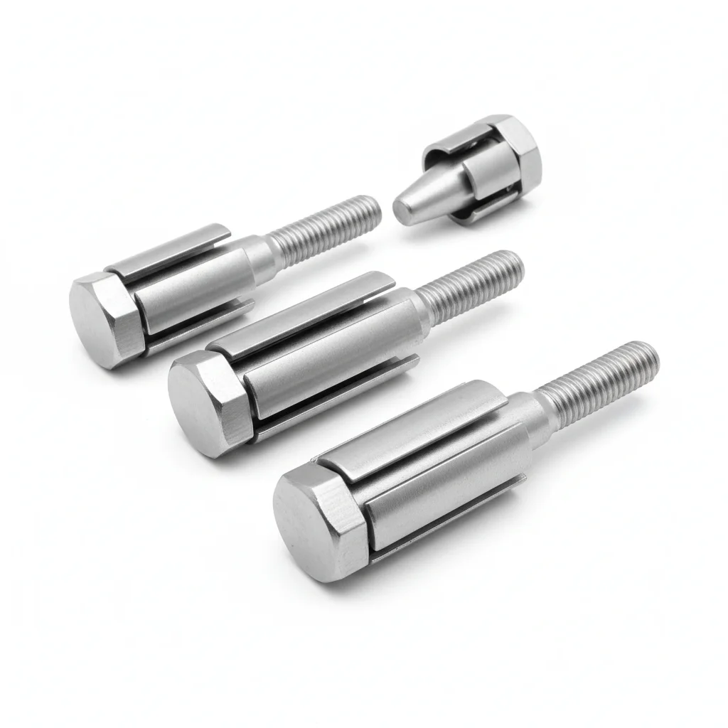
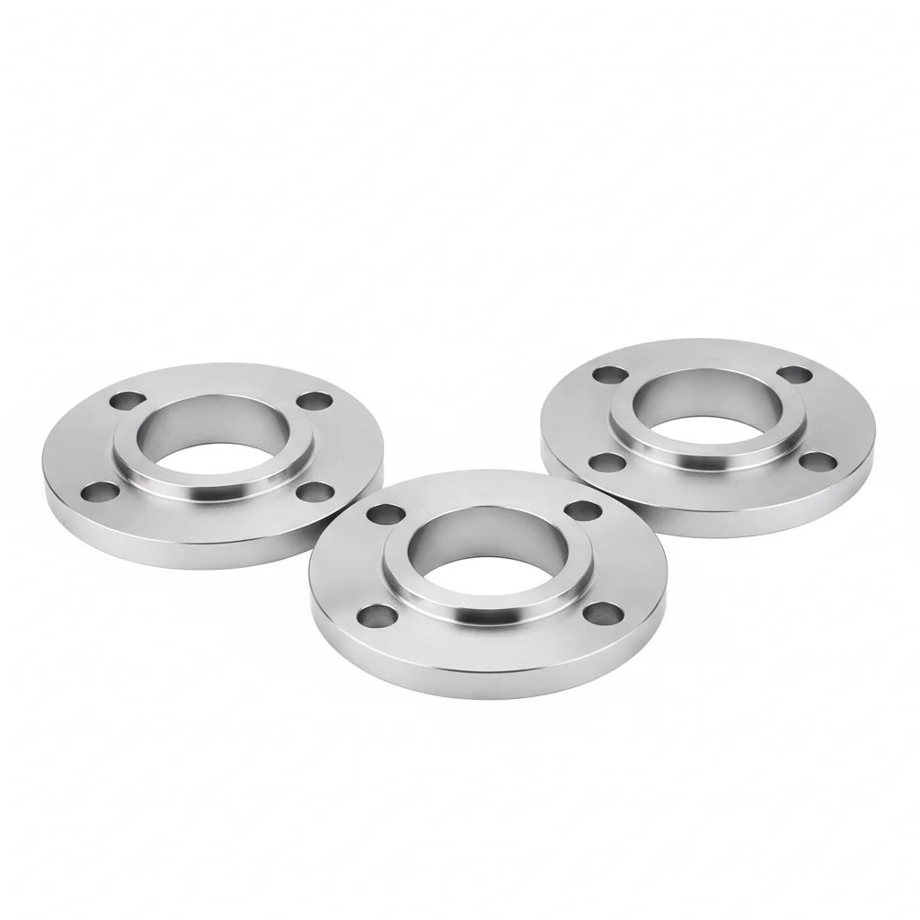
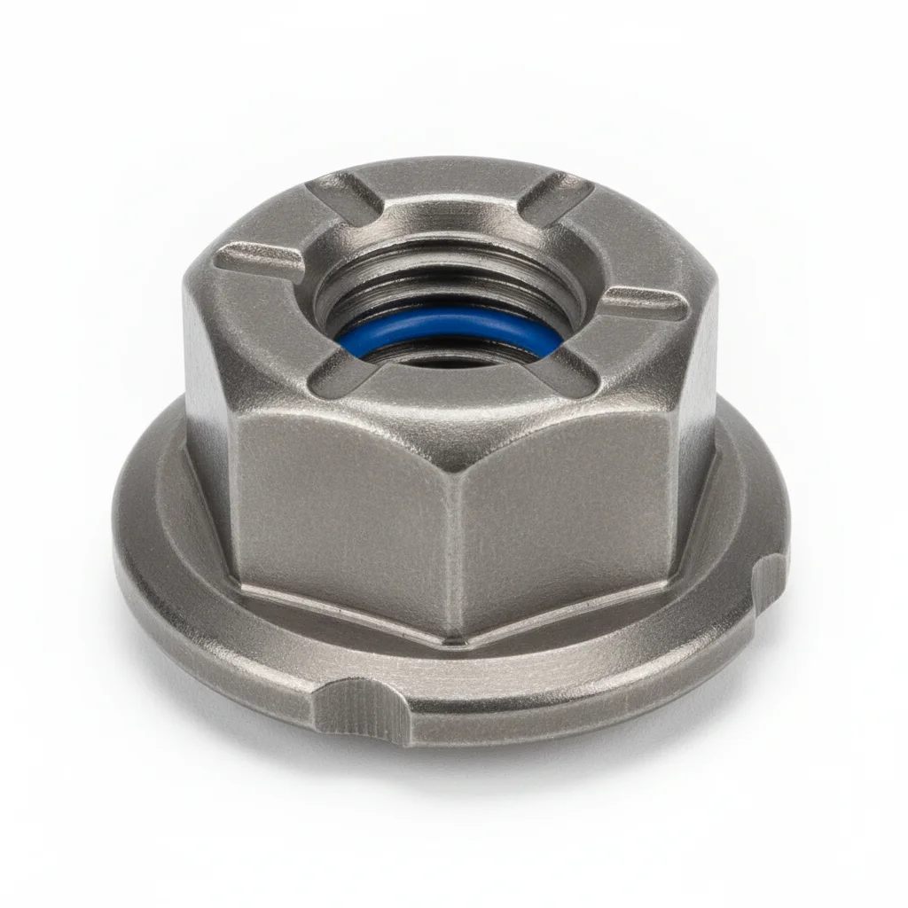
| Base Bolt | Flange | Access Door Hinge | Lock Nut | Anti-Corrosion Grease | |
|---|---|---|---|---|---|
| SPEC | M20×300, Q235B hot-dip galvanized, grade 4.8 | 400×400×16mm, Q235B welded + hot-dip galvanized | 304 stainless steel stamped, load capacity ≥ 50kg | M20, Nordlock wedge-locking washer | Lithium grease NLGI-2, apply to threads to prevent seizing |
| MATERIAL | Q235B | Q235B | 304 stainless steel | — | — |
| GRADE | Grade 4.8 | — | — | — | — |
| FINISH | HDG >=55um per ISO 1461 | HDG >=55um per ISO 1461 | HDG >=55um per ISO 1461 | HDG >=55um per ISO 1461 | HDG >=55um per ISO 1461 |
| CORROSION | C3 (ISO 12944-2) | C3 (ISO 12944-2) | C3 (ISO 12944-2) | C3 (ISO 12944-2) | C3 (ISO 12944-2) |
| TEMP | -20°C to +80°C | -20°C to +80°C | -20°C to +80°C | -20°C to +80°C | -20°C to +80°C |
| WEIGHT | ~0.5 kg/piece | ~0.5 kg/piece | ~0.5 kg/piece | ~0.5 kg/piece | ~0.5 kg/piece |
| MOQ | 100 pcs | 100 pcs | 100 pcs | 100 pcs | 100 pcs |
| PACK | VCI paper + carton | VCI paper + carton | VCI paper + carton | VCI paper + carton | VCI paper + carton |
| STD | ISO 898-1, GB/T 3098.1 | ISO 898-1, GB/T 3098.1 | ISO 898-1, GB/T 3098.1 | ISO 898-1, GB/T 3098.1 | ISO 898-1, GB/T 3098.1 |
| USE | Grade 8.8 | Q235B welded + hot-dip galvanized | Load capacity ≥ 50kg | Nordlock wedge-locking washer | Apply to threads to prevent seizing |
PROCEDURE
- Set the anchor bolt cage in the foundation form with a positioning template so the M20×300 Q235B bolts hold a pattern tolerance of ≤2 mm and verticality ≤1:100.
- After the concrete cures, bed the 400×400×16 mm Q235B flange on high-strength non-shrink grout, filling the 30–50 mm gap between flange and foundation.
- Bolt tightening: tighten the Grade 4.8 M20 nuts in stages in a diagonal sequence, reaching the design preload in 2-3 passes with a calibrated torque wrench; avoid over-tightening on one side, which deforms the flange.
- Tighten the nuts in a star pattern to the torque specified on the design drawing, using a calibrated wrench; verify seating of the flange against the grout.
- Seal the exposed thread ends and the flange-to-grout joint with an approved corrosion-protection compound, then mark the nut-to-bolt position for visual checks.
COMMON ERRORS
| ✕ WRONG | CONSEQUENCE | ✓ CORRECT |
|---|---|---|
| Overtightening the M20 grade 8.8 bolt without a torque wrench, relying on feel | Nut can yield or the bolt can stretch beyond its elastic range, lowering clamp load and inviting loosening under wind vibration. | Use a calibrated torque wrench and follow the design torque value for a grade 8.8 M20 bolt; tighten in a star pattern. |
| Leaving the grout pocket unsealed or using ordinary cement mortar that shrinks | Water and chlorides reach the buried portion of the anchor bolts and the base plate, driving corrosion that weakens the connection. | Fill the 30–50 mm gap with high-strength non-shrink grout and apply a flexible sealant at the flange edge to keep moisture out. |
| Installing the lock nut without the Nordlock wedge-locking washer or with the washer reversed | The wedge-locking action is lost, so vibration from wind and traffic can back the nut off over time. | Place the Nordlock washer with its cam faces against the nut and the flange, then tighten to the specified torque. |
MAINTENANCE
Check the nut-and-bolt index marks and flange-to-grout seal seasonally, and after any high-wind event; re-torque any fastener that has rotated or lost preload to the design value, and repair coating damage to the HDG surface promptly.
Plan B · 304 Stainless Steel Heavy-Duty Light Pole Hardware
C4 Harsh per ISO 12944-2 for coastal humidity
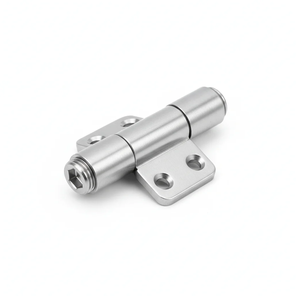
| Base Bolt | Flange | Reinforced Hinge | Lock Nut | Anti-Corrosion Coating | |
|---|---|---|---|---|---|
| SPEC | M24×350, A2-70 stainless steel, tensile strength ≥ 700MPa | 500×500×20mm, 304 stainless steel integral forging | 316L stainless steel precision casting, load capacity ≥ 100kg | M24, A2-70 + Nordlock washer | Epoxy zinc-rich primer + polyurethane topcoat, salt spray resistance 1000h |
| MATERIAL | 70 stainless steel | 304 stainless steel | 316L stainless steel | — | Polyurethane |
| GRADE | A2-70 | — | — | A2-70 | — |
| FINISH | HDG >=55um per ISO 1461 | HDG >=55um per ISO 1461 | HDG >=55um per ISO 1461 | HDG >=55um per ISO 1461 | HDG >=55um per ISO 1461 |
| CORROSION | C3 (ISO 12944-2) | C3 (ISO 12944-2) | C3 (ISO 12944-2) | C3 (ISO 12944-2) | C3 (ISO 12944-2) |
| TEMP | -20°C to +80°C | -20°C to +80°C | -20°C to +80°C | -20°C to +80°C | -20°C to +80°C |
| WEIGHT | ~0.5 kg/piece | ~0.5 kg/piece | ~0.5 kg/piece | ~0.5 kg/piece | ~0.5 kg/piece |
| MOQ | 100 pcs | 100 pcs | 100 pcs | 100 pcs | 100 pcs |
| PACK | VCI paper + carton | VCI paper + carton | VCI paper + carton | VCI paper + carton | VCI paper + carton |
| STD | ISO 898-1, GB/T 3098.1 | ISO 898-1, GB/T 3098.1 | ISO 898-1, GB/T 3098.1 | ISO 898-1, GB/T 3098.1 | ISO 898-1, GB/T 3098.1 |
| USE | Tensile strength ≥ 700MPa | 304 stainless steel integral forging | Load capacity ≥ 100kg | A2-70 + Nordlock washer | Salt spray resistance 1000h |
PROCEDURE
- Clean the M24×350 A2-70 threads and 304 flange mating faces with acetone to remove salt deposits and oils.
- Apply epoxy zinc-rich primer to the flange base and use PTFE-coated washers under A2-70 nuts.
- Set the 500×500×20mm integral forging on the anchor cage, aligning to the foundation template within 2mm.
- Tighten M24 A2-70 lock nuts in a cross pattern with a calibrated torque wrench to the specified preload.
- Seal the base plate edge with polyurethane topcoat and install a corrosion monitoring coupon nearby.
COMMON ERRORS
| ✕ WRONG | CONSEQUENCE | ✓ CORRECT |
|---|---|---|
| Mixing carbon steel washers with 304 stainless bolts in coastal salt air | Galvanic corrosion at the washer-bolt interface accelerates thread pitting and reduces clamping force. | Use only A2-70 stainless washers and nuts with the 304 base bolts. |
| Tightening M24 A2-70 nuts without lubrication on threads | High friction causes inaccurate preload and galling of stainless threads, leading to premature loosening. | Apply anti-seize grease specified for stainless steel to the threads before torquing. |
MAINTENANCE
Inspect seasonally for rust staining or salt deposits around the base flange; re-torque any A2-70 bolt that has lost more than 15% tension. Replace bolts with pitting depth exceeding 0.3mm; perform ultrasonic thickness checks every 2 years on the flange.
Plan C · 6061 Aluminum Alloy Extreme Light Pole Hardware
C5-M Extreme per ISO 12944-2 for typhoon zones
| Aluminum Alloy Base Bolt | Aluminum Alloy Flange | Special Alloy Hinge | Smart Monitoring Tag | Dedicated Installation Tool | |
|---|---|---|---|---|---|
| SPEC | M27×400, 7075-T6 aluminum alloy, tensile strength ≥ 570MPa | 600×600×25mm, 6061-T6 integral extrusion | Inconel 625 precision casting, load capacity ≥ 150kg | RFID chip, records installation time and inspection records | Hydraulic torque wrench, preload controllable ±3% |
| MATERIAL | Aluminum alloy | 6061-T6 | — | EPDM Rubber | — |
| GRADE | — | — | — | — | — |
| FINISH | HDG >=55um per ISO 1461 | HDG >=55um per ISO 1461 | HDG >=55um per ISO 1461 | HDG >=55um per ISO 1461 | HDG >=55um per ISO 1461 |
| CORROSION | C3 (ISO 12944-2) | C3 (ISO 12944-2) | C3 (ISO 12944-2) | Not applicable (polymer) | C3 (ISO 12944-2) |
| TEMP | -20°C to +80°C | -20°C to +80°C | -20°C to +80°C | -20°C to +80°C | -20°C to +80°C |
| WEIGHT | ~0.5 kg/piece | ~0.5 kg/piece | ~0.5 kg/piece | ~0.5 kg/piece | ~0.5 kg/piece |
| MOQ | 100 pcs | 100 pcs | 100 pcs | 100 pcs | 100 pcs |
| PACK | VCI paper + carton | VCI paper + carton | VCI paper + carton | VCI paper + carton | VCI paper + carton |
| STD | ISO 898-1, GB/T 3098.1 | ISO 898-1, GB/T 3098.1 | ISO 898-1, GB/T 3098.1 | ISO 898-1, GB/T 3098.1 | ISO 898-1, GB/T 3098.1 |
| USE | Tensile strength ≥ 570MPa | 6061-T6 integral extrusion | Load capacity ≥ 150kg | Records installation time and inspection records | Preload controllable ±3% |
PROCEDURE
- Degrease 7075-T6 bolt threads and 6061-T6 flange surfaces with MEK to remove all contaminants before assembly.
- Apply marine-grade anti-corrosion compound to the threads and use PTFE-encapsulated washers to prevent galvanic corrosion.
- Align the 600×600×25mm flange to the anchor cage within 0.3mm using the positioning template.
- Tighten M27×400 bolts with a hydraulic tensioner to achieve the specified preload with ±3% accuracy.
- Verify material grade on 10% of fasteners using PMI, then install the RFID smart tag with installation data.
COMMON ERRORS
| ✕ WRONG | CONSEQUENCE | ✓ CORRECT |
|---|---|---|
| Using standard steel tools that leave ferrous contamination on aluminum alloy hardware | Embedded iron particles initiate localized corrosion in the high-strength aluminum, leading to stress cracking. | Use dedicated non-marking tools and clean surfaces immediately if any contamination is suspected. |
| Ignoring the torque specification and over-tightening the 7075-T6 bolts | Over-preload can cause thread stripping or stress corrosion cracking in the aluminum alloy, risking sudden failure. | Use the hydraulic tensioner with preload control and verify each bolt against the specified range. |
MAINTENANCE
Inspect the hardware before each typhoon season and after any major storm event. Check for cracks or deformation; verify preload is within 15% of design. Replace any bolt with corrosion depth greater than 0.3mm or signs of fatigue. Use the RFID tag to track inspection history and schedule NDT every 3 years.
SELECTION GUIDE
How to choose a light pole hardware solution based on wind resistance level?
| Operating condition | Recommended option | Key basis |
|---|---|---|
| Inland Areas / Wind resistance ≤ level 10 / Conventional Landscapes | Plan A · Q235B standard hardware (grade 4.8 base bolts, hot-dip galvanized) | Per GB 50009 load code, Beaufort scale 10; hot-dip galvanized zinc layer ≥85μm; Q235B flange welded + galvanized; design life 15-25 years |
| Coastal Areas / Wind resistance level 10-14 / High Humidity | Plan B · 304 stainless steel heavy-duty (A2-70 base bolts, integral-forged flange) | C4 Harsh per ISO 12944-2; A2-70 tensile strength ≥700MPa; 304 corrosion rate <0.01mm/year; Nordlock wedge-locking washer |
| Typhoon Zones / Wind resistance ≥ level 14 / Ultra-Long Life | Plan C · 6061 aluminum alloy extreme (7075-T6 base bolts, 6061-T6 integral extrusion flange) | C5-M Extreme per ISO 12944-2; 7075-T6 tensile strength ≥570MPa; 6061-T6 integral extrusion; Inconel 625 hinge load capacity ≥150kg |
REFERENCED STANDARDS
Technical Basis and Reference Standards
"Road Lighting Poles"
Safety Requirements for Floodlights"Technical Conditions and Test Methods for Solar Home Photovoltaic Power Systems"
Urban Road Lighting Design Standard"Building Structure Load Code"
Steel Structure Design Standard"Mechanical Properties of Fasteners - Bolts, Screws and Studs"
Building Structure Load CodeStandard Specification for Aluminum and Aluminum-Alloy Sheet and Plate
SUPPLIER CAPABILITY
Quality, Delivery & Customization
Quality Control
- ✓MTC material certificates with every batch
- ✓Key parts sampled for hardness/salt spray/torque coefficient
- ✓100% inspection or AQL sampling before shipment
Delivery
- ✓Standard parts made to order: 7-15 days
- ✓Custom parts: 25-45 days
- ✓FOB/CIF/DDP supported
Customization
- ✓Drawing review and material matching
- ✓Non-standard sizes/heads/threads
- ✓Small-batch prototyping supported
Certification
- ✓Material certificates (MTC)
- ✓Spectrographic analysis reports
- ✓Salt spray test reports (on request)
MOQ: No MOQ for standard parts; custom parts assessed by process complexity
FAQ
Frequently Asked Questions
RELATED READING
Keep Reading & Next Step
NEXT: SELECTION & RFQ
Outdoor Cable ClampFollow this page's selection path to the same-scenario RFQ page.
RELATED TOPIC
Luminaire Mounting BracketsRELATED TOPIC
Grounding RodsBEYOND TECHNICAL SPECS
Finding the right factory, controlling quality, delivering on time — that's the real challenge. We cover fasteners, rubber, plastics, industrial textiles. One team, end to end.
SEE CAPABILITIES →