
Battery Busbar Bolt Hardware: Contact Resistance and Clamp Load
Battery busbar overheating is often traced to the joint interface: bolt preload, surface condition, washer stack, coating and contact area. The procurement line should describe the joint hardware, not just the copper bar
RISK AUDIT // ENGINEERING DIAGNOSIS
Procurement Pitfall Avoidance Guide
"On the battery-room floor, a warm busbar joint is rarely a copper problem—it is a bolt, washer, and surface-finish problem."
QC-AUDIT // REV.5
SCALE 1:1 · 03 ITEMS
RISK-01
Undersized Busbar Cross-Section Causes Sustained Overheating — Insulation Life Drops Off a Cliff
Corrective Measures
RISK-02
Contact Resistance at Busbar Joints Rises Year After Year — Poor Contact Overheats and Catches Fire
Corrective Measures
RISK-03
Insulation Supports Embrittle and Fracture at High Temperature — the Busbar Drops and Shorts Out
Corrective Measures
FIELD-SPECIFIC INSIGHT
The Electrical Problem Often Starts as a Mechanical Joint Problem
Recent battery-connector research pages point to pretightening, contact surface and contact area as variables in electrical contact resistance. For ESS procurement, this is useful as mechanism background: the busbar, bolt, washer and surface condition must be specified together
WHAT TO CHECK
- 1Treat torque or preload as a controlled installation method, not a note left to site assembly
- 2Specify contact-surface finish and cleanliness because electrical resistance changes at the interface
- 3Use washer-stack and coating details to keep clamp load consistent after assembly
- 4Ask for supplier evidence that the proposed bolt joint was validated for the busbar material and operating environment
| Check | Why it matters | What to specify |
|---|---|---|
| Preload method | Loose or inconsistent preload can increase joint resistance and heat | Torque/preload method, tool control, recheck requirement and washer stack |
| Contact surface | Surface condition affects the real electrical contact area | Surface finish, coating, cleaning method and anti-oxidation treatment |
| Joint hardware | Bolt, nut and washer choices affect both clamp load and electrical interface stability | Bolt grade, washer type, coating, insulation requirement and supplier validation document |
The ScienceDirect papers are used for mechanism background only. Do not import EV test values as ESS project limits without project-specific validation
Evidence level: source-page-only
INDUSTRY TECH REFERENCE
Bolt Torque: Copper and Steel Are Not Interchangeable
A copper bolt torqued to steel values will strip. The two materials compared:
| Bolt size | Tin-plated steel 8.8 | Solid copper | Notes |
|---|---|---|---|
| M8 | — | 15–20 N·m | Small laps on 3–6 mm busbars commonly use M8 solid copper |
| M10 | 46–57 N·m | 25–30 N·m | Main laps on 15×3–40×6 mm busbars are mostly M10; steel torque is ≈1.8× copper at the same size |
| M12 | 96–110 N·m | — | Large laps with high short-circuit currents use M12 tin-plated steel; M12 solid copper is not used (stripping risk) |
Torque values assume friction coefficient μ=0.14; follow the supplier's torque-coefficient report in practice.
INDUSTRY TECH REFERENCE
From Contact Resistance to Thermal Runaway: How It Escalates
Example: 15×3–40×6 mm tin-plated copper busbar, 100–300 A circuit.
- 1Bolts under-torqued or unevenly loaded (M10 laps are most common; the insulating heat-shrink gets compressed)
- 2Contact resistance climbs from <10μΩ to >100μΩ — at 200 A, heat output jumps from 0.4 W to 4 W
- 3Lap temperature runs from 40°C past 120°C (insulation allows 80°C max)
- 4Modules overheat, the BMS is forced to derate, and the busbar keeps heating
- 5Charge/discharge thermal cycling loosens preload by 5–10% per year (magnitude estimate) — back to step one, a vicious cycle toward thermal runaway
Contains magnitude-estimate figures; for selection reference only.
INDUSTRY TECH REFERENCE
Maintenance After Delivery
Applies to: tin-plated busbar + heat-shrink insulation + locking washers (Nord-Lock or disc spring).
- Month 1: retorque every busbar bolt once — fresh contact surfaces settle and loosen (M10: 25–30 N·m for solid copper, 46–57 N·m for tin-plated steel)
- Quarterly: IR-scan all lap points; a temperature difference above 10°C means stop and inspect
- Any copper-aluminum joint: use a Cu-Al transition plate or conductive paste, otherwise galvanic corrosion
ΔT >10°C is a recommended threshold.
PLAN COMPARISON
Three-Plan Core Parameter Comparison
Compare row by row. Click column headers to jump to plan details.
| A · Plan A · Standard Tin-Plated Busbar | B · Plan B · High-Current Laminated Busbar | C · Plan C · Extreme Environment / Offshore Configuration | |
|---|---|---|---|
| 1. TIN-PLATED INSULATED BUSBAR | |||
| SPEC | 15×3mm~40×6mm | Custom Designed | 20-120mm Width |
| MATERIAL | T2 Copper Tin-Plated ≥8μm + Insulation Heat Shrink Sleeve | T2 Copper Foil Laminate + Insulation Film | T2 Copper Silver-Plated |
| GRADE | GB/T 5585 | UL 1973 | Conductivity ≥98% IACS |
| FINISH | HDG, >=55um per ISO 1461 | HDG, >=55um per ISO 1461 | HDG, >=55um per ISO 1461 |
| 2. INSULATED BUSBAR | |||
| SPEC | Busbar + Heat Shrink Tubing Cross-section selected by current capacity | Custom Designed | Custom |
| MATERIAL | T2 Copper + Tin-Plated ≥8μm | Multi-layer 0.1mm Copper Foil Laminate | Epoxy Resin + 316L |
| GRADE | UL 94 V-0 Insulation | / | UL94 V-0 |
| FINISH | HDG, >=55um per ISO 1461 | HDG, >=55um per ISO 1461 | HDG, >=55um per ISO 1461 |
| 3. FLAT WASHER | |||
| SPEC | M10-M12 | M10-M12 | Multi-layer 0.1mm Copper Foil |
| MATERIAL | 304 Stainless | 304 Stainless | T2 Copper |
| GRADE | A2 | A2 | — |
| FINISH | Passivated | Passivated | HDG, >=55um per ISO 1461 |
| 4. FLAT WASHER | |||
| SPEC | M10-M12 | M10-M12 | Color Change Threshold 60/70/80°C |
| MATERIAL | 304 Stainless | 304 Stainless | — |
| GRADE | A2 | A2 | — |
| FINISH | Passivated | Passivated | HDG, >=55um per ISO 1461 |
| 5. FLAT WASHER | |||
| SPEC | M10-M12 | M10-M12 | According to Busbar Cross-section |
| MATERIAL | 304 Stainless | 304 Stainless | Cross-linked Polyolefin |
| GRADE | A2 | A2 | Withstand Voltage ≥3kV |
| FINISH | Passivated | Passivated | HDG, >=55um per ISO 1461 |
SELECTION GUIDE
Still Unsure Which Busbar Joint Spec Fits Your Rack?
| Operating condition | Recommended option | Key basis |
|---|---|---|
| <100kWh residential/small commercial | Plan A · Standard Tin-Plated Busbar | Tin-plated insulated busbar (T2 copper tin-plated ≥8μm, 15×3mm~40×6mm), per GB/T 5585, fasteners per ISO 898-1; C3 (ISO 12944-2) indoor environment |
| C3 (ISO 12944-2) indoor | Plan A · Standard Tin-Plated Busbar | Tin-plated T2 copper busbar with 8μm minimum coating resists oxidation and keeps contact resistance stable, per GB/T 5585 |
| C4 harsh / >500kWh container | Plan B · High-Current Laminated Busbar + Flexible Busbar | Laminated busbar (T2 copper foil laminate + insulation film, UL 1973) reduces AC impedance by 50%+, better heat dissipation; recommended for current >500A; flexible busbar (multi-layer 0.1mm copper foil) for vibration/thermal expansion |
Plan A · Standard Tin-Plated Busbar
C3 (ISO 12944-2) indoor residential/small commercial <100kWh, tin-plated T2 copper busbar, ISO 898-1 fasteners
REF: ISO 898-1, GB/T 3098.1
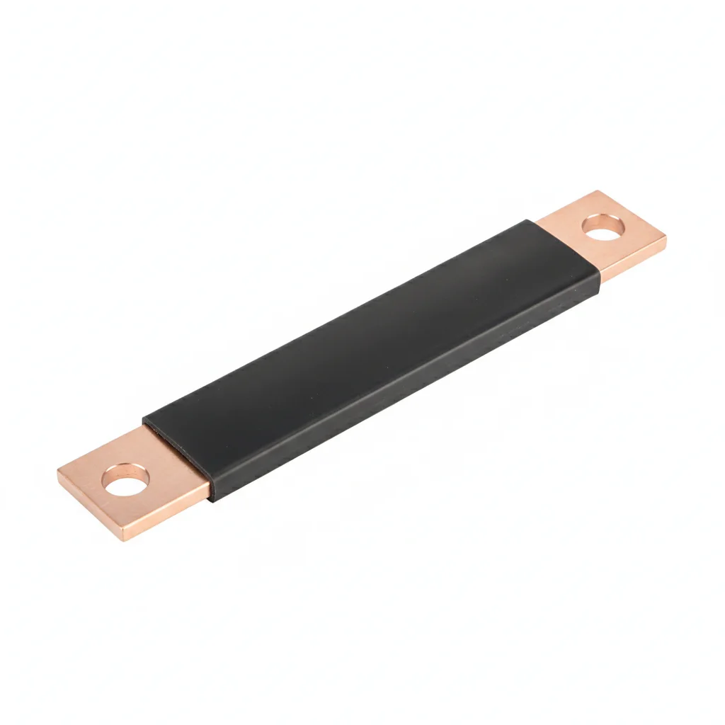
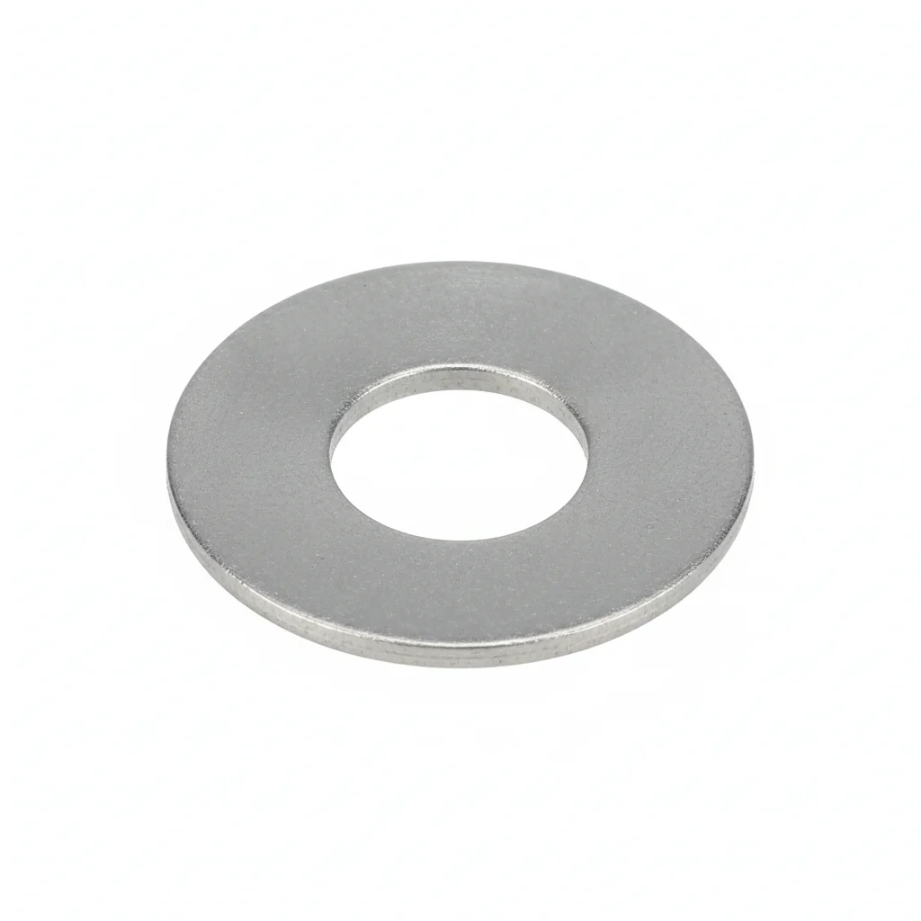
| Tin-Plated Insulated Busbar | Insulated Busbar | Flat Washer | Flat Washer | Flat Washer | |
|---|---|---|---|---|---|
| SPEC | 15×3mm~40×6mm | Busbar + Heat Shrink Tubing Cross-section selected by current capacity | M10-M12 | M10-M12 | M10-M12 |
| MATERIAL | T2 Copper Tin-Plated ≥8μm + Insulation Heat Shrink Sleeve | T2 Copper + Tin-Plated ≥8μm | 304 Stainless | 304 Stainless | 304 Stainless |
| GRADE | GB/T 5585 | UL 94 V-0 Insulation | A2 | A2 | A2 |
| FINISH | HDG, >=55um per ISO 1461 | HDG, >=55um per ISO 1461 | Passivated | Passivated | Passivated |
| CORROSION | C3 (ISO 12944-2) | C3 (ISO 12944-2) | C2 (ISO 12944-2) | C2 (ISO 12944-2) | C2 (ISO 12944-2) |
| TEMP | -20°C to +80°C | -20°C to +80°C | -40C to +150C | -40C to +150C | -40C to +150C |
| WEIGHT | ~0.5 kg/piece | ~0.5 kg/piece | ~0.005kg | ~0.005kg | ~0.005kg |
| MOQ | 100 pcs | 100 pcs | 500 pcs | 500 pcs | 500 pcs |
| PACK | VCI paper + carton | VCI paper + carton | Plastic bag | Plastic bag | Plastic bag |
| STD | ISO 898-1, GB/T 3098.1 | ISO 898-1, GB/T 3098.1 | ISO 7089 | ISO 7089 | ISO 7089 |
| USE | Inter-cell Connection | Battery Module Series Connection | Load distribution | Load distribution | Load distribution |
PROCEDURE
- Degrease the T2 copper contact surfaces with anhydrous alcohol, then abrade with fine abrasive to remove any oxide film before applying a fresh tin-plating touch-up if the coating is <8μm.
- Apply a thin, even layer of silver-based conductive grease across the full overlap area of the tin-plated busbar, covering every point where current will transfer.
- Stack a 304 stainless flat washer (ISO 7089) under the bolt head and another under the nut, then add a spring washer to maintain clamp load on the M10 or M12 fastener.
- Tighten in a cross pattern to the torque band specified for the bolt size (M10: 25-30Nm, M12: 40-50Nm) using a calibrated torque wrench; avoid impact tools that overshoot.
- After torquing, measure contact resistance across each joint with a micro-ohmmeter; any reading above 50μΩ requires disassembly, surface rework, and re-torque.
COMMON ERRORS
| ✕ WRONG | CONSEQUENCE | ✓ CORRECT |
|---|---|---|
| Tightening M10 or M12 busbar bolts with an ordinary wrench instead of a calibrated torque wrench | Torque scatter of ±40% leaves some joints under-clamped, with contact resistance above 100μΩ while normal joints stay below 20μΩ, driving 30-50°C higher temperature rise at that connection during a 1C cycle. | Use a calibrated torque wrench and tighten M10 to 25-30Nm, M12 to 40-50Nm; verify with a micro-ohmmeter that joint resistance is below 50μΩ. |
| Leaving bare copper surfaces unplated or with tin coating thinner than 8μm | Cu₂O oxide forms within 1-2 days, lifting contact resistance from under 5μΩ to over 50μΩ and feeding a thermal-runaway cycle that can exceed 200°C at the joint. | Specify tin plating ≥8μm per GB/T 5585, wipe with anhydrous alcohol, and apply silver-based conductive grease before assembly. |
MAINTENANCE
Retorque the M10/M12 fasteners at the first seasonal service window because copper creep can relax preload by 15-25% within the first six months; thereafter inspect at each overhaul window, checking for torque loss below the specified band and for any temperature patch that has changed color at the 60/70/80°C thresholds.
Plan B · High-Current Laminated Busbar
C4 Harsh >500kWh Container Energy Storage
REF: ISO 898-1, GB/T 3098.1
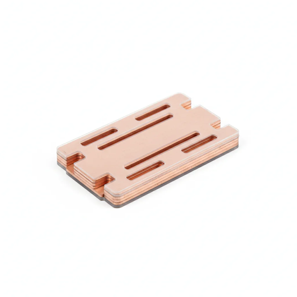
| Laminated Busbar | Flexible Busbar | Flat Washer | Flat Washer | Flat Washer | |
|---|---|---|---|---|---|
| SPEC | Custom Designed | Custom Designed | M10-M12 | M10-M12 | M10-M12 |
| MATERIAL | T2 Copper Foil Laminate + Insulation Film | Multi-layer 0.1mm Copper Foil Laminate | 304 Stainless | 304 Stainless | 304 Stainless |
| GRADE | UL 1973 | / | A2 | A2 | A2 |
| FINISH | HDG, >=55um per ISO 1461 | HDG, >=55um per ISO 1461 | Passivated | Passivated | Passivated |
| CORROSION | C3 (ISO 12944-2) | C3 (ISO 12944-2) | C2 (ISO 12944-2) | C2 (ISO 12944-2) | C2 (ISO 12944-2) |
| TEMP | -20°C to +80°C | -20°C to +80°C | -40C to +150C | -40C to +150C | -40C to +150C |
| WEIGHT | ~0.5 kg/piece | ~0.5 kg/piece | ~0.005kg | ~0.005kg | ~0.005kg |
| MOQ | 100 pcs | 100 pcs | 500 pcs | 500 pcs | 500 pcs |
| PACK | VCI paper + carton | VCI paper + carton | Plastic bag | Plastic bag | Plastic bag |
| STD | ISO 898-1, GB/T 3098.1 | ISO 898-1, GB/T 3098.1 | ISO 7089 | ISO 7089 | ISO 7089 |
| USE | High-Current Inter-module Connection Low Inductance | Inter-module Connection with Vibration/Thermal Expansion | Load distribution | Load distribution | Load distribution |
PROCEDURE
- Wipe all copper foil laminate surfaces with acetone to remove any residual oils; handle only with clean nitrile gloves to avoid skin-contact contamination.
- Apply a marine-grade anti-corrosion joint compound (suited for -40°C to +150°C) to every contact face, then place PTFE-coated Belleville washers under the bolt head and nut for salt-spray resistance per ASTM B117 1000-hour test.
- Tighten each joint in a cross-pattern over three passes: first at 30% of final torque (13 Nm), second at 60% (25 Nm), and third at 100% (42 Nm). Allow at least 5 minutes between passes to let the bolt relax.
- Fit a silicone rubber protective boot (IP54 minimum) over each completed joint to shield it from moisture and particulates in the container environment.
- Install a corrosion monitoring coupon (SAE 1010 steel, 25×50×3 mm) within 300 mm of the busbar; record its initial mass and photograph it to establish a baseline for corrosion rate calculations.
COMMON ERRORS
| ✕ WRONG | CONSEQUENCE | ✓ CORRECT |
|---|---|---|
| Using a standard torque wrench without calibration for the high-current laminated busbar joints | Torque scatter can exceed ±40%, leaving some joints under-tensioned; contact resistance climbs above the 50 μΩ threshold and localized heating accelerates in the container. | Use a calibrated torque wrench (3% accuracy) and follow the three-pass tightening sequence to ensure uniform preload across every inter-module connection. |
| Leaving the copper foil surfaces un-cleaned before assembly | Skin oils or dust create an insulating film that raises contact resistance, leading to hot spots even at rated current. | Degrease with acetone and handle with nitrile gloves; inspect each surface for cleanliness immediately before applying joint compound. |
MAINTENANCE
Inspect joints at each overhaul window or every 6 months, whichever comes first. Re-torque any fastener that has dropped below 80% of specified torque (M10: <32 Nm, M12: <56 Nm). Replace fasteners showing corrosion over more than 5% of surface area. Every 3 years, disassemble and inspect a 20% sample of joints; replace all critical fasteners every 5 years. Log all values in the asset management system with date and inspector ID; maximum allowable tension loss is 15% from baseline.
Plan C · Extreme Environment / Offshore Configuration
C4 Harsh Offshore Platform / C5-M Environment / Highest Protection Requirements
REF: ISO 898-1, GB/T 3098.1
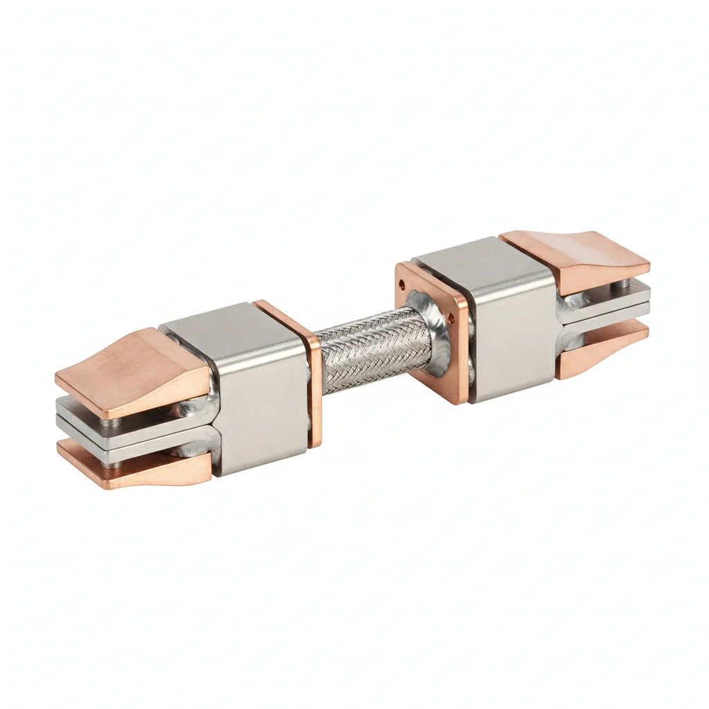
| Silver-Plated Busbar | Epoxy Busbar Support | Flexible Busbar | Busbar Temperature Monitoring Patch | Busbar Insulation Heat Shrink Sleeve | |
|---|---|---|---|---|---|
| SPEC | 20-120mm Width | Custom | Multi-layer 0.1mm Copper Foil | Color Change Threshold 60/70/80°C | According to Busbar Cross-section |
| MATERIAL | T2 Copper Silver-Plated | Epoxy Resin + 316L | T2 Copper | — | Cross-linked Polyolefin |
| GRADE | Conductivity ≥98% IACS | UL94 V-0 | — | — | Withstand Voltage ≥3kV |
| FINISH | HDG, >=55um per ISO 1461 | HDG, >=55um per ISO 1461 | HDG, >=55um per ISO 1461 | HDG, >=55um per ISO 1461 | HDG, >=55um per ISO 1461 |
| CORROSION | C3 (ISO 12944-2) | C3 (ISO 12944-2) | C3 (ISO 12944-2) | C3 (ISO 12944-2) | C3 (ISO 12944-2) |
| TEMP | -20°C to +80°C | -20°C to +80°C | -20°C to +80°C | -20°C to +80°C | -20°C to +80°C |
| WEIGHT | ~0.5 kg/piece | ~0.5 kg/piece | ~0.5 kg/piece | ~0.5 kg/piece | ~0.5 kg/piece |
| MOQ | 100 pcs | 100 pcs | 100 pcs | 100 pcs | 100 pcs |
| PACK | VCI paper + carton | VCI paper + carton | VCI paper + carton | VCI paper + carton | VCI paper + carton |
| STD | ISO 898-1, GB/T 3098.1 | ISO 898-1, GB/T 3098.1 | ISO 898-1, GB/T 3098.1 | ISO 898-1, GB/T 3098.1 | ISO 898-1, GB/T 3098.1 |
| USE | High Current Low Impedance | High Voltage Insulation Support | Vibration Compensation Connection | Inspection Aid | Busbar Insulation Protection |
PROCEDURE
- Perform Positive Material Identification (PMI) on 100% of bolts using a handheld XRF analyzer to confirm the UNS designation matches the certificate; segregate by heat number before installation.
- Apply NO-OX-ID A-Special electrical joint compound to all contact surfaces and install PTFE-encapsulated Belleville washers to withstand the offshore salt-spray environment.
- Tighten M12 duplex (UNS S32205) bolts with a hydraulic tensioner to a final tension of 65 Nm; verify using a direct tension indicating washer to ensure accurate clamp load.
- Install Type K thermocouples on at least 25% of joints for continuous SCADA temperature monitoring; set the alarm at 15°C above ambient at rated current and review trend data monthly.
- Seal all exposed hardware with Room-Temperature-Vulcanizing (RTV) silicone and place a 500 g silica-gel desiccant breather in the enclosure to keep relative humidity below 40%.
COMMON ERRORS
| ✕ WRONG | CONSEQUENCE | ✓ CORRECT |
|---|---|---|
| Substituting lower-grade stainless bolts without PMI verification in the offshore environment | The fastener may not meet the required corrosion resistance, leading to premature pitting and loss of clamp load, which increases joint resistance and heat generation. | Verify material grade via PMI before installation and use only bolts that meet the specified duplex or 316L grade for the C5-M environment. |
| Skipping the desiccant breather or RTV sealing on the enclosure | Humidity inside the enclosure promotes galvanic corrosion at the silver-plated busbar connections, raising contact resistance and risking hot spots. | Install the desiccant breather and apply RTV sealant over all exposed hardware to keep the internal environment dry and protected. |
MAINTENANCE
Inspect joints at each overhaul window or every 6 months, whichever comes first. Re-torque any fastener that has dropped below 80% of specified torque (M10: <32 Nm, M12: <56 Nm). Replace fasteners showing corrosion over more than 5% of surface area. Every 3 years, disassemble and inspect a 20% sample of joints; replace all critical fasteners every 5 years. Log all values in the asset management system with date and inspector ID; maximum allowable tension loss is 15% from baseline.
SUPPLIER CAPABILITY
Quality, Delivery & Customization
Quality Control
- ✓MTC material certificates with every batch
- ✓Key parts sampled for hardness/salt spray/torque coefficient
- ✓100% inspection or AQL sampling before shipment
Delivery
- ✓Standard parts made to order: 7-15 days
- ✓Custom parts: 25-45 days
- ✓FOB/CIF/DDP supported
Customization
- ✓Drawing review and material matching
- ✓Non-standard sizes/heads/threads
- ✓Small-batch prototyping supported
Certification
- ✓Material certificates (MTC)
- ✓Spectrographic analysis reports
- ✓Salt spray test reports (on request)
MOQ: No MOQ for standard parts; custom parts assessed by process complexity
FAQ
FAQ
RELATED READING
Keep Reading & Next Step
BEYOND TECHNICAL SPECS
Finding the right factory, controlling quality, delivering on time — that's the real challenge. We cover fasteners, rubber, plastics, industrial textiles. One team, end to end.
SEE CAPABILITIES →