Breather Valve Selection for Energy Storage
Temperature swings during charge/discharge cycles cause pressure changes that can compromise cabinet seals. A breather valve prevents water ingress and condensation. This page compares PTFE membrane, metal sintered, and pressure relief valve options for indoor, outdoor, and harsh environments
RISK AUDIT // ENGINEERING DIAGNOSIS
Procurement Pitfall Guide
"Three installation mistakes that turn a breather valve into a water inlet."
QC-AUDIT // REV.5
SCALE 1:1 · 03 ITEMS
RISK-01
Undersized Breather Valve Gives Too Little Relief Flow — the Cabinet Bursts in Thermal Runaway
Corrective Measures
RISK-02
Membrane Breather Valve Embrittles from UV Aging — the Protection Fails and Water Gets In
Corrective Measures
RISK-03
Breather Valve Installed Where Water Collects and Splashes — It Is an Open Floodgate
Corrective Measures
FIELD-SPECIFIC INSIGHT
Breather Valve Selection: 3 Critical Checks
The breather valve is a small but critical component for energy storage cabinet integrity. The wrong choice can lead to condensation, water ingress, or inadequate pressure relief during thermal runaway. Use these checks to specify the right valve for your environment
WHAT TO CHECK
- 1PTFE membrane valves (M12×1.5) suit indoor/general outdoor (C3) for daily pressure balance; clogging risk in dusty/salt-spray environments
- 2Metal sintered valves (M20×1.5, 316L) suit outdoor/coastal (C4) with higher flow and IP69K; add safety pressure relief valve for thermal runaway
- 3Installation position: upper-middle side of cabinet, membrane outward. Bottom or upside-down installation causes water ingress
| Check | Why it matters | What to specify |
|---|---|---|
| Environment corrosivity category | Determines material and IP rating needed to prevent corrosion and clogging | C3 (indoor) → PTFE+PA66; C4 (outdoor) → 316L metal sintered; C5-M (offshore) → 316L or duplex |
| Pressure relief requirement for thermal runaway | Standard breather valve cannot relieve rapid pressure rise; cabinet may rupture | Add safety pressure relief valve (DN50, 50-200mbar) or explosion-proof valve (DN80) per UL 9540A |
| Installation position and orientation | Wrong position causes water ingress or condensation; insulation resistance drops | Upper-middle side, membrane outward, not at bottom or top |
All breather valves must be tested per IEC 60529 for IP rating. For thermal runaway scenarios, refer to UL 9540A and NFPA 855 for pressure relief requirements
Evidence level: source-page-only
INDUSTRY TECH REFERENCE
The Thermal-Runaway Relief Loop: Spec Each Part
Check the relief loop part by part — material, size, and replacement cycle; one wrong torque or material anywhere and the relief path fails.
| Part | Material / scheme | Size | Key parameters | Replacement cycle |
|---|---|---|---|---|
| Vent flange bolts | 316L | M6–M8 | Torque must be precise — too tight cracks the membrane, too loose fails to relieve | 5–8 years |
| Body sealing membrane | 316L body + PTFE membrane | Match body | Resistant to electrolyte | 5–8 years |
| Flange gasket | Graphite-reinforced PTFE | Match flange | Rated -200 to 260°C | 5–8 years |
| Opening-pressure setting | Per cabinet design pressure | — | Set 5–15 kPa (about 50–70% of the cabinet design pressure) | — |
"Opening pressure ≈50–70% of cabinet design pressure" is a magnitude estimate; the 5–8-year replacement cycle follows O&M practice.
INDUSTRY TECH REFERENCE
How Cabinet Pressure Escalates During Thermal Runaway
Example: LFP cell thermal runaway — follow the pressure path from cell to cabinet relief.
- 1Thermal runaway generates gas fast and cabinet pressure spikes — LFP relief pressure is on the order of 20–40 kPa (below NCM's 100–200 kPa)
- 2Set the vent opening pressure at 5–15 kPa, roughly 50–70% of the cabinet design pressure
- 3Flange-bolt torque must be precise — too tight cracks the PTFE membrane, too loose fails to relieve
- 4Verify relief capacity against UL 9540A thermal-runaway testing (governs vent capacity)
- 5Replace flange bolts and gaskets on a 5–8-year cycle and re-measure the opening pressure
"Relief pressures 20–40 kPa / 100–200 kPa" and "opening pressure ≈50–70% of design pressure" are magnitude estimates.
INDUSTRY TECH REFERENCE
After the Vent Is Installed: Torque, Gasket, and Recertification
Installing the vent is not the end — installation quality and periodic recertification decide whether it operates when it must.
- Flange bolts M6–M8 in 316L, torqued to precise values — too tight cracks the membrane, too loose fails to relieve
- Gasket: graphite-reinforced PTFE (rated -200 to 260°C); PTFE membrane for electrolyte-contact sealing
- Verify relief capacity against UL 9540A and installation/fire separation against NFPA 855, both matched to the cabinet design pressure
- Replace flange bolts and gaskets on a 5–8-year cycle and re-verify the opening-pressure setting
PLAN COMPARISON
Three-Plan Core Parameter Comparison
Compare row by row. Click column headers to jump to plan details.
| A · Plan A · Standard PTFE Breather Valve | B · Plan B · Outdoor Harsh + Safety Pressure Relief | C · Plan C · Extreme Environment / Offshore Configuration | |
|---|---|---|---|
| 1. MEMBRANE WATERPROOF BREATHER VALVE | |||
| SPEC | M12×1.5 | M20×1.5 | M20×1.5 |
| MATERIAL | PTFE Membrane + PA66 | 316L Stainless Steel | 316L |
| GRADE | IP68 | IP69K | Ventilation Capacity ≥2000ml/min |
| FINISH | HDG >=55um per ISO 1461 | HDG >=55um per ISO 1461 | HDG >=55um per ISO 1461 |
| 2. FLAT WASHER | |||
| SPEC | M10-M12 | DN50 50-200mbar | DN80 |
| MATERIAL | 304 Stainless | 316L + EPDM | 316L + Rupture Disc |
| GRADE | A2 | / | Set 50-200mbar |
| FINISH | Passivated | HDG >=55um per ISO 1461 | HDG >=55um per ISO 1461 |
| 3. FLAT WASHER | |||
| SPEC | M10-M12 | M10-M12 | M12×1.5 |
| MATERIAL | 304 Stainless | 304 Stainless | 316L + Electric Heat Tracing |
| GRADE | A2 | A2 | — |
| FINISH | Passivated | Passivated | HDG >=55um per ISO 1461 |
| 4. FLAT WASHER | |||
| SPEC | M10-M12 | M10-M12 | M12×1.5 |
| MATERIAL | 304 Stainless | 304 Stainless | 316L + Activated Carbon |
| GRADE | A2 | A2 | — |
| FINISH | Passivated | Passivated | HDG >=55um per ISO 1461 |
| 5. FLAT WASHER | |||
| SPEC | M10-M12 | M10-M12 | Handheld |
| MATERIAL | 304 Stainless | 304 Stainless | — |
| GRADE | A2 | A2 | — |
| FINISH | Passivated | Passivated | HDG >=55um per ISO 1461 |
SELECTION GUIDE
Choosing the right valve? Let's narrow it down.
| Operating condition | Recommended option | Key basis |
|---|---|---|
| Small indoor storage (C3) | Plan A · Standard PTFE Breather Valve | PTFE membrane + PA66, M12×1.5, IP68 per IEC 60529; passive daily pressure balance, no power required |
| General outdoor (C3) | Plan A · Standard PTFE Breather Valve | PTFE membrane valve suits indoor/general outdoor for daily pressure balance; clogging risk in dusty/salt-spray environments |
| Large outdoor capacity (C4) | Plan B · Metal Sintered + Safety Pressure Relief Valve | 316L metal sintered, M20×1.5, IP69K, higher flow; add safety pressure relief valve (DN50, 50-200mbar, 316L+EPDM) for thermal runaway emergencies; 1m³ cabinet requires ventilation ≥500ml/min@7kPa |
Plan A · Standard PTFE Breather Valve
C3 standard per ISO 12944-2
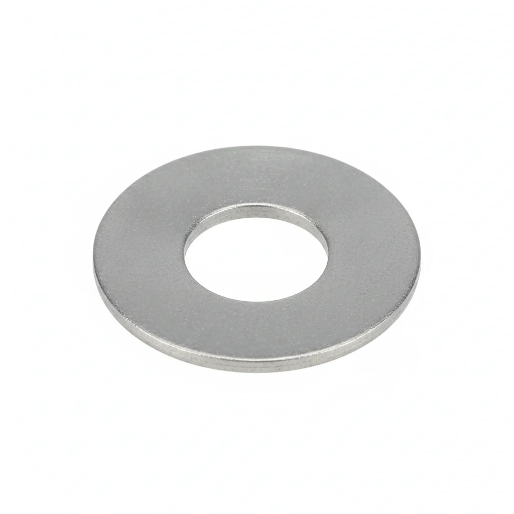
| Membrane Waterproof Breather Valve | Flat Washer | Flat Washer | Flat Washer | Flat Washer | |
|---|---|---|---|---|---|
| SPEC | M12×1.5 | M10-M12 | M10-M12 | M10-M12 | M10-M12 |
| MATERIAL | PTFE Membrane + PA66 | 304 Stainless | 304 Stainless | 304 Stainless | 304 Stainless |
| GRADE | IP68 | A2 | A2 | A2 | A2 |
| FINISH | HDG >=55um per ISO 1461 | Passivated | Passivated | Passivated | Passivated |
| CORROSION | C3 (ISO 12944-2) | C3 (ISO 12944-2) | C3 (ISO 12944-2) | C3 (ISO 12944-2) | C3 (ISO 12944-2) |
| TEMP | -20°C to +80°C | -20°C to +80°C | -20°C to +80°C | -20°C to +80°C | -20°C to +80°C |
| WEIGHT | ~0.5 kg/piece | ~0.005kg | ~0.005kg | ~0.005kg | ~0.005kg |
| MOQ | 100 pcs | 500 pcs | 500 pcs | 500 pcs | 500 pcs |
| PACK | VCI paper + carton | Plastic bag | Plastic bag | Plastic bag | Plastic bag |
| STD | ISO 898-1, GB/T 3098.1 | ISO 7089 | ISO 7089 | ISO 7089 | ISO 7089 |
| USE | Daily Pressure Balance | Load distribution | Load distribution | Load distribution | Load distribution |
PROCEDURE
- Clean the mounting surface on the cabinet and the valve port with isopropyl alcohol; ensure no debris or old sealant remains.
- Position the PTFE membrane breather valve (M12×1.5) on the upper-middle side of the cabinet, with the membrane facing outward and tilted down 5–10° to shed rainwater.
- Insert the valve through the mounting hole and secure it with the supplied PA66 nut; hand-tighten first to align the valve body without cross-threading.
- Tighten the nut with a torque wrench to the value specified in the product datasheet (refer to the M12×1.5 thread specification) — do not overtighten, as this can deform the PTFE membrane.
- Apply a bead of silicone sealant around the valve base within a 50mm range to enhance waterproofing, then allow it to cure per the sealant instructions.
- Perform a 10-minute water spray test on the valve area to confirm no water ingress inside the cabinet before closing the access panel.
COMMON ERRORS
| ✕ WRONG | CONSEQUENCE | ✓ CORRECT |
|---|---|---|
| Mounting the breather valve at the bottom of the cabinet. | Accumulated water or condensation can submerge the PTFE membrane, blocking ventilation and creating a direct water ingress path into the cabinet. | Install on the upper-middle side of the cabinet, at least 400mm from the bottom and about 200mm from the top, with the membrane facing outward. |
| Installing the valve upside down with the membrane facing inward. | Rainwater or drips directly impact the membrane surface; under water pressure above 5kPa, the 0.2μm pores can be breached, leading to water entry and insulation failure. | Orient the valve so the PTFE membrane faces outward and is tilted downward by 5–10° to deflect direct rain impact. |
MAINTENANCE
Inspect the breather valve quarterly for dust or salt buildup on the PTFE membrane; gently blow off surface dust with compressed air from the outside. In coastal or dusty areas, inspect monthly. Replace the valve when its ventilation capacity drops by more than 50% (test with a handheld breather valve tester).
Plan B · Outdoor Harsh + Safety Pressure Relief
C4 Harsh per ISO 12944-2
| Metal Sintered Breather Valve | Safety Pressure Relief Valve | Flat Washer | Flat Washer | Flat Washer | |
|---|---|---|---|---|---|
| SPEC | M20×1.5 | DN50 50-200mbar | M10-M12 | M10-M12 | M10-M12 |
| MATERIAL | 316L Stainless Steel | 316L + EPDM | 304 Stainless | 304 Stainless | 304 Stainless |
| GRADE | IP69K | / | A2 | A2 | A2 |
| FINISH | HDG >=55um per ISO 1461 | HDG >=55um per ISO 1461 | Passivated | Passivated | Passivated |
| CORROSION | C3 (ISO 12944-2) | C3 (ISO 12944-2) | C3 (ISO 12944-2) | C3 (ISO 12944-2) | C3 (ISO 12944-2) |
| TEMP | -20°C to +80°C | -20°C to +80°C | -20°C to +80°C | -20°C to +80°C | -20°C to +80°C |
| WEIGHT | ~0.5 kg/piece | ~0.5 kg/piece | ~0.005kg | ~0.005kg | ~0.005kg |
| MOQ | 100 pcs | 100 pcs | 500 pcs | 500 pcs | 500 pcs |
| PACK | VCI paper + carton | VCI paper + carton | Plastic bag | Plastic bag | Plastic bag |
| STD | ISO 898-1, GB/T 3098.1 | ISO 898-1, GB/T 3098.1 | ISO 7089 | ISO 7089 | ISO 7089 |
| USE | Harsh Outdoor Ventilation | Thermal Runaway Emergency Pressure Relief | Load distribution | Load distribution | Load distribution |
PROCEDURE
- Position the M20×1.5 metal sintered breather valve on the cabinet's upper-middle side, ensuring the sintered element faces outward and tilts down 5–10° to shed rainwater.
- Clean the mounting surface with a solvent to remove salt deposits and grease, then verify the gasket seat is free of burrs.
- Secure the valve with 304 stainless steel washers and bolts, tightening in a cross pattern to the torque specified for the M20 thread.
- For the DN50 safety pressure relief valve, set the opening pressure within the 50–200mbar range and mount it on the top or rear panel, away from personnel pathways.
- After installation, conduct a water spray test for 10 minutes to confirm no seepage, and verify the breather valve's ventilation capacity with a handheld tester if available.
COMMON ERRORS
| ✕ WRONG | CONSEQUENCE | ✓ CORRECT |
|---|---|---|
| Installing the breather valve at the bottom of the cabinet | Accumulated water submerges the sintered element, blocking ventilation and creating a water ingress path, leading to corrosion and insulation failure. | Mount the valve on the upper-middle side (200mm from top, ≥400mm from bottom) with the membrane facing outward. |
| Overtightening the pressure relief valve flange bolts | Can crack the EPDM seal or distort the valve body, causing leakage or failure to open at the set pressure during thermal runaway. | Tighten flange bolts to the manufacturer's specified torque using a calibrated wrench, ensuring even compression. |
MAINTENANCE
Seasonally inspect the metal sintered breather valve for clogging from salt spray or dust; clean the sintered element with compressed air if ventilation capacity drops. Verify the safety pressure relief valve operates freely at its set range (50–200mbar) and replace any corroded 316L or EPDM components. In coastal areas, increase checks to monthly.
Plan C · Extreme Environment / Offshore Configuration
C5-M Extreme per ISO 12944-2
| High Flow Breather Valve | Explosion-Proof Pressure Relief Valve | Heated Anti-Freeze Breather Valve | Breather Valve with Built-in Filter Element | Breather Valve Tester | |
|---|---|---|---|---|---|
| SPEC | M20×1.5 | DN80 | M12×1.5 | M12×1.5 | Handheld |
| MATERIAL | 316L | 316L + Rupture Disc | 316L + Electric Heat Tracing | 316L + Activated Carbon | — |
| GRADE | Ventilation Capacity ≥2000ml/min | Set 50-200mbar | — | — | — |
| FINISH | HDG >=55um per ISO 1461 | HDG >=55um per ISO 1461 | HDG >=55um per ISO 1461 | HDG >=55um per ISO 1461 | HDG >=55um per ISO 1461 |
| CORROSION | C3 (ISO 12944-2) | C3 (ISO 12944-2) | C3 (ISO 12944-2) | C3 (ISO 12944-2) | C3 (ISO 12944-2) |
| TEMP | -20°C to +80°C | -20°C to +80°C | -20°C to +80°C | -20°C to +80°C | -20°C to +80°C |
| WEIGHT | ~0.5 kg/piece | ~0.5 kg/piece | ~0.5 kg/piece | ~0.5 kg/piece | ~0.5 kg/piece |
| MOQ | 100 pcs | 100 pcs | 100 pcs | 100 pcs | 100 pcs |
| PACK | VCI paper + carton | VCI paper + carton | VCI paper + carton | VCI paper + carton | VCI paper + carton |
| STD | ISO 898-1, GB/T 3098.1 | ISO 898-1, GB/T 3098.1 | ISO 898-1, GB/T 3098.1 | ISO 898-1, GB/T 3098.1 | ISO 898-1, GB/T 3098.1 |
| USE | Large Energy Storage Cabinets | Thermal Runaway Emergency Pressure Relief | Anti-Freeze in Cold Regions | Prevent Harmful Gas Ingress | Periodic Ventilation Capacity Testing |
PROCEDURE
- Degrease the mounting surface with MEK solvent and verify surface roughness Ra <1.6um to ensure a proper seal for the M20×1.5 high flow breather valve.
- Apply marine-grade anti-corrosion compound to threads and use PTFE-encapsulated washers to prevent galvanic corrosion in offshore environments.
- Mount the DN80 explosion-proof pressure relief valve with 316L bolts and graphite-reinforced PTFE gaskets, setting the rupture disc to 50–200mbar.
- For cold regions, install the heated anti-freeze breather valve (M12×1.5) ensuring the heat tracing is connected and functional.
- After all valves are fitted, perform a 10-minute water spray test and verify ventilation capacity of the high flow valve (≥2000ml/min) using the tester.
COMMON ERRORS
| ✕ WRONG | CONSEQUENCE | ✓ CORRECT |
|---|---|---|
| Using standard carbon steel bolts for the explosion-proof valve flange | Corrosion in offshore salt-laden air leads to bolt failure, compromising the pressure relief seal and risking cabinet rupture during thermal runaway. | Use 316L stainless steel or duplex bolts with graphite-reinforced PTFE gaskets to resist electrolyte and high-temperature creep. |
| Positioning the breather valve where it faces direct rain impact without a drip edge | Rainwater can breach the membrane under pressure, causing water ingress and insulation resistance drop below 1MΩ. | Install the valve tilted downward 5–10° with a rain cap above to divert water flow. |
MAINTENANCE
At each overhaul window, test the ventilation capacity of the high flow breather valve (≥2000ml/min) and replace the activated carbon filter element if harmful gas ingress is suspected. Verify the rupture disc of the explosion-proof valve is intact and set within 50–200mbar. Inspect all 316L and duplex components for pitting or crevice corrosion, especially in C5-M environments.
SUPPLIER CAPABILITY
Quality, Delivery & Customization
Quality Control
- ✓MTC material certificates with every batch
- ✓Key parts sampled for hardness/salt spray/torque coefficient
- ✓100% inspection or AQL sampling before shipment
Delivery
- ✓Standard parts made to order: 7-15 days
- ✓Custom parts: 25-45 days
- ✓FOB/CIF/DDP supported
Customization
- ✓Drawing review and material matching
- ✓Non-standard sizes/heads/threads
- ✓Small-batch prototyping supported
Certification
- ✓Material certificates (MTC)
- ✓Spectrographic analysis reports
- ✓Salt spray test reports (on request)
MOQ: No MOQ for standard parts; custom parts assessed by process complexity
FAQ
FAQ
RELATED READING
Keep Reading & Next Step
BEYOND TECHNICAL SPECS
Finding the right factory, controlling quality, delivering on time — that's the real challenge. We cover fasteners, rubber, plastics, industrial textiles. One team, end to end.
SEE CAPABILITIES →