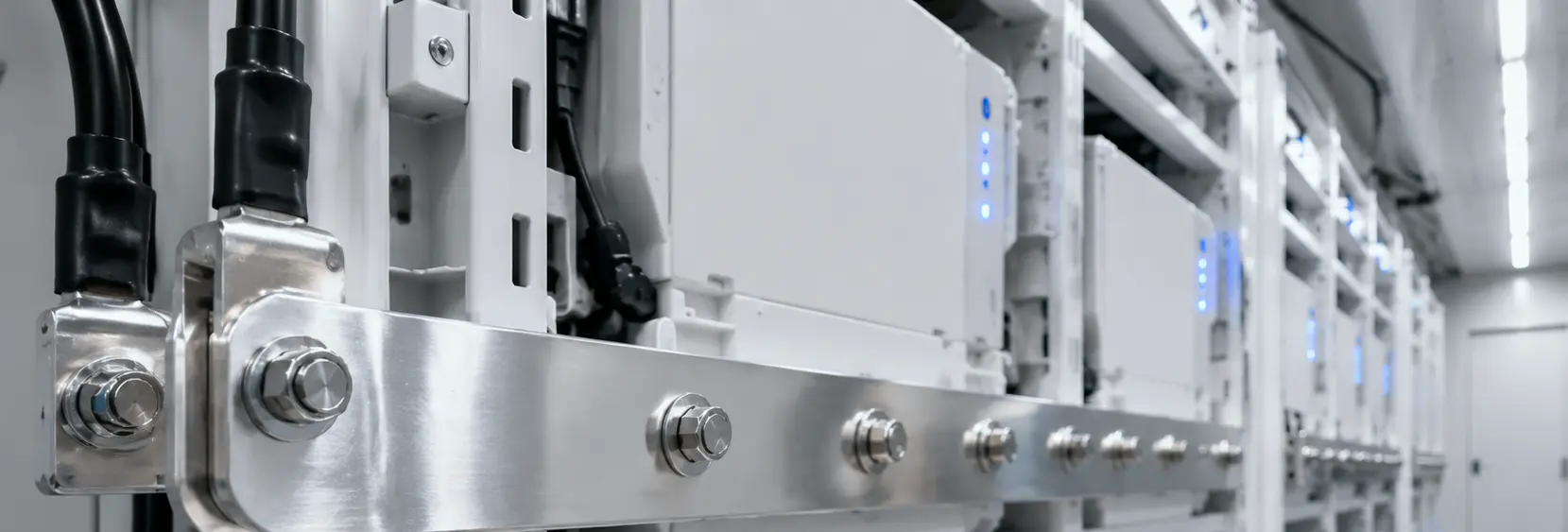
Energy Storage Busbar Connector Selection: Materials, Coatings & Risks
Busbar connections are critical for power transmission in energy storage systems. This page compares three solutions for commercial/industrial indoor (≤800A, DC 1000V) and container outdoor (≤1600A, DC 1500V) applications, covering tin-plated copper busbar, bolt grades, and insulation spacers. Key risks include voltage drop from contact resistance, galvanic corrosion between copper and aluminum, and creepage failure. Selection criteria per IEC 61439 and GB/T 5585
RISK AUDIT // ENGINEERING DIAGNOSIS
Procurement Pitfall Avoidance Guide
"Costly busbar connection failures—voltage drop, galvanic corrosion, and creepage—often trace back to overlooked lap-joint details."
QC-AUDIT // REV.5
SCALE 1:1 · 03 ITEMS
RISK-01
Excessive voltage drop at busbar lap joints causes system efficiency loss
Corrective Measures
RISK-02
Galvanic corrosion from contact between dissimilar metals
Corrective Measures
RISK-03
Insufficient insulation distance leads to creepage
Corrective Measures
FIELD-SPECIFIC INSIGHT
Busbar Connection Risk Checklist for Procurement Engineers
In energy storage busbar connections, the most overlooked engineering difference is the combined effect of contact resistance, galvanic corrosion potential, and creepage distance under DC voltage. While current rating and voltage are primary specs, the actual failure chain often starts at the lap joint interface
WHAT TO CHECK
- 1Contact resistance at busbar lap joints: specify ≤10μΩ per IEC 61439-1; higher values cause voltage drop and heat buildup, accelerating oxidation
- 2Galvanic corrosion risk: when copper busbar contacts aluminum terminals, potential difference is 2. 0V; specify tin plating on copper and use bimetallic transition pieces or insulating washers
- 3Creepage distance for DC 1500V: minimum 25mm per GB/T 14048.1 for pollution degree 3; verify insulation spacer thickness and surface tracking resistance
- 4Bolt preload consistency: use torque-controlled tightening and specify re-torque intervals; tension loss beyond 15% requires fastener replacement
- 5Environmental corrosivity: match coating (tin plating thickness, bolt grade, and coating type) to ISO 12944-2 corrosivity category (C3, C4, C5-M)
| Check | Why it matters | What to specify |
|---|---|---|
| Contact resistance at lap joint | Exceeds 10μΩ → voltage drop → heat → oxidation → resistance increase → thermal runaway risk | Require ≤10μΩ per IEC 61439-1; verify with micro-ohmmeter during FAT |
| Galvanic corrosion protection | Copper-aluminum contact in humid environment accelerates corrosion, increasing resistance | Tin-plate copper busbar; use bimetallic washers or transition pieces; avoid direct contact |
| Creepage distance for DC voltage | Insufficient distance leads to creepage breakdown, especially in dusty/humid conditions | Minimum 25mm for 1500V DC, pollution degree 3 per GB/T 14048.1 |
| Bolt grade and coating | Grade 8.8 vs 10.9 vs 12.9 affects clamping force; coating affects corrosion resistance | Select grade per torque requirements; coating per corrosivity category (e. G. , Dacromet for C5-M) |
| Insulation spacer material and thickness | SMC/DMC must withstand DC voltage and tracking; thickness affects creepage distance | Verify dielectric strength and thickness per system voltage; request test reports |
All values and standards are from public sources. Actual project specifications must be verified with system designer and applicable local codes
Evidence level: standard-backed
INDUSTRY TECH REFERENCE
Busbar Lap Surfaces: Tin or Silver Plating
Bare copper laps oxidize into a high-resistance film, so a coating is mandatory — choose tin or silver by current class.
| Surface treatment | Notes | Where it applies |
|---|---|---|
| Bare copper (unplated) | Surface oxidizes into a high-resistance Cu₂O film | Must be tin- or silver-plated before lap jointing |
| Tin plating | Coating about 5–15 μm (magnitude estimate), oxidation protection | Standard current-carrying lap joints |
| Silver plating | Coating for critical joints | Critical joints above 200 A |
Tin coating 5–15 μm is a magnitude estimate.
INDUSTRY TECH REFERENCE
Three Acceptance Checks for High-Current Laps
Contact resistance, creepage, and Cu-Al joints — each has a verifiable acceptance criterion.
PLAN COMPARISON
Three-Plan Core Parameter Comparison
Compare row by row. Click column headers to jump to plan details.
| A · Plan A · Commercial & Industrial Energy Storage Standard Type | B · Plan B · Container Energy Storage Enhanced Type | C · Plan C · Container Energy Storage Enhanced Type | |
|---|---|---|---|
| 1. TIN-PLATED COPPER BUSBAR | |||
| SPEC | 30×5 ~ 80×10 mm | 30×5 ~ 80×10 mm | 30×5 ~ 80×10 mm |
| MATERIAL | T2 Copper + Tin Plating ≥8μm | T2 Copper + Tin Plating ≥8μm | T2 Copper + Tin Plating ≥8μm |
| FINISH | HDG >=55um per ISO 1461 | HDG >=55um per ISO 1461 | HDG >=55um per ISO 1461 |
| 2. INSULATION SPACER | |||
| SPEC | 3mm/5mm thick | 3mm/5mm thick | 3mm/5mm thick |
| MATERIAL | SMC/DMC | SMC/DMC | SMC/DMC |
| FINISH | HDG >=55um per ISO 1461 | HDG >=55um per ISO 1461 | HDG >=55um per ISO 1461 |
| 3. HEX BOLT KIT | |||
| SPEC | M10×30 ~ M12×40 | M10×30 ~ M12×40 | M10×30 ~ M12×40 |
| MATERIAL | Carbon Steel Grade 8.8 + Galvanized | Carbon Steel Grade 8.8 + Galvanized | Carbon Steel Grade 8.8 + Dacromet + Topcoat |
| GRADE | 8.8 | 10.9 | 12.9 |
| FINISH | HDG >=55um per ISO 1461 | HDG >=55um per ISO 1461 | HDG >=55um per ISO 1461 |
SELECTION GUIDE
Torn between Plan A and Plan B for your energy storage busbar connections?
| Operating condition | Recommended option | Key basis |
|---|---|---|
| DC 1000V and below, indoor | Plan A · Commercial & Industrial Standard | Tin-plated copper busbar (T2 copper tin plating ≥8μm, 30×5~80×10mm) + SMC/DMC insulation spacer + grade 8.8 bolts; C3 per ISO 12944-2; per IEC 61439 and GB/T 5585 |
| DC 1500V, outdoor/container | Plan B · Container Energy Storage Enhanced | Outdoor container rated ≤1600A; thicker tin or silver plating, increased insulation spacer withstand rating; C4 per ISO 12944-2; grade 10.9 bolts |
| Rated current ≤800A | Tin-plated copper busbar | Tin plating ≥8μm protects copper from oxidation for 10-15 years in atmospheric environment |
| Rated current >800A | Silver-plated copper busbar | Silver plating ≥5μm provides best conductivity and oxidation resistance, reduces contact resistance |
Plan A · Commercial & Industrial Energy Storage Standard Type
C3 per ISO 12944-2
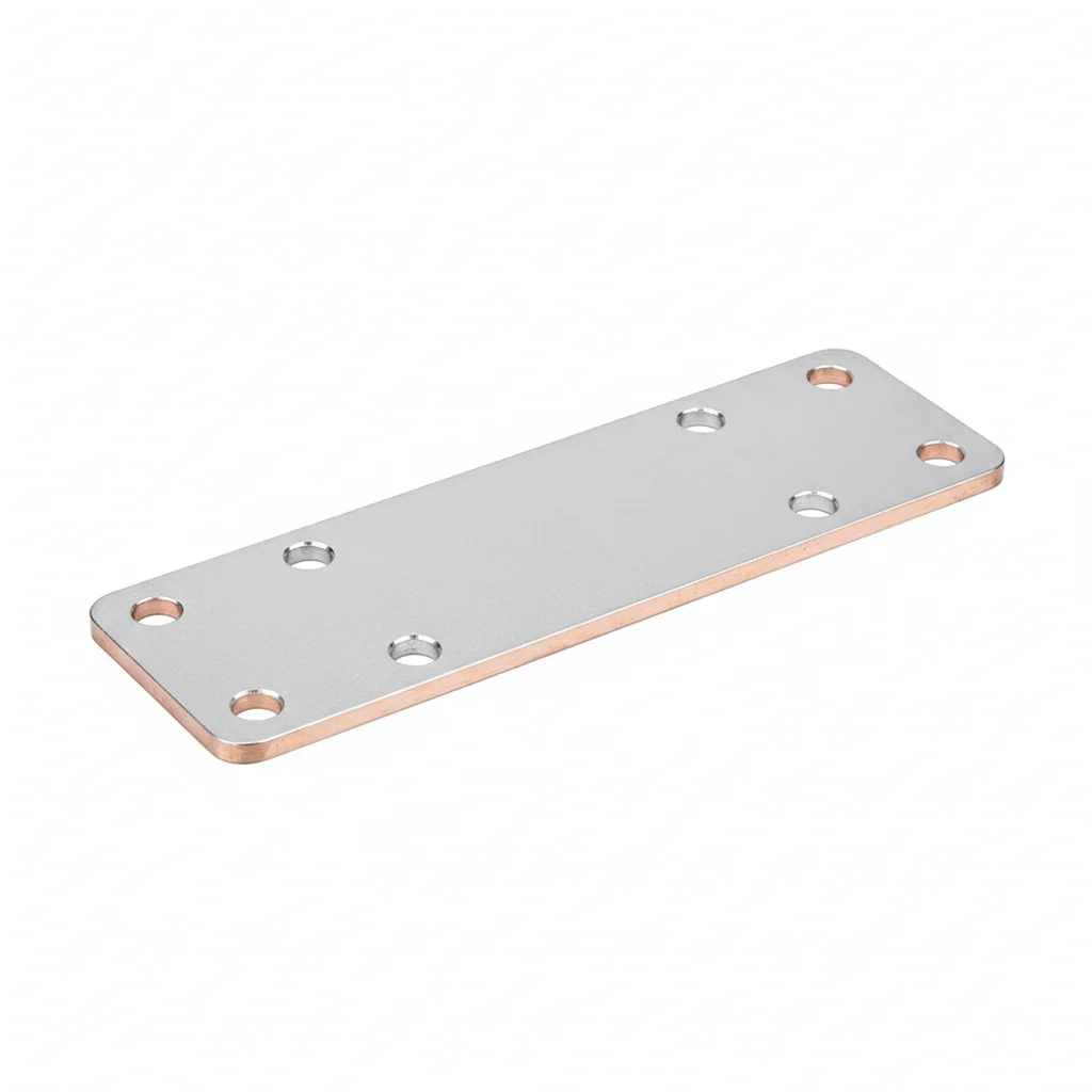
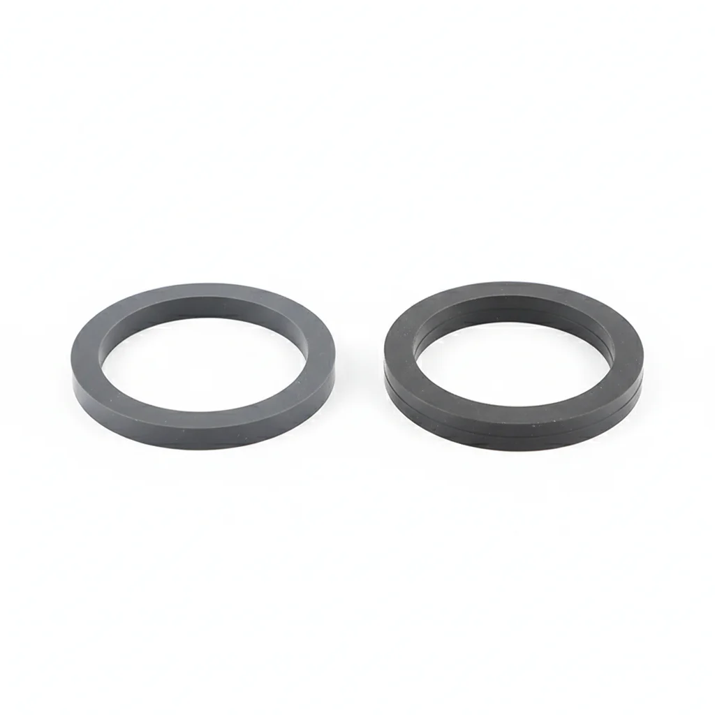
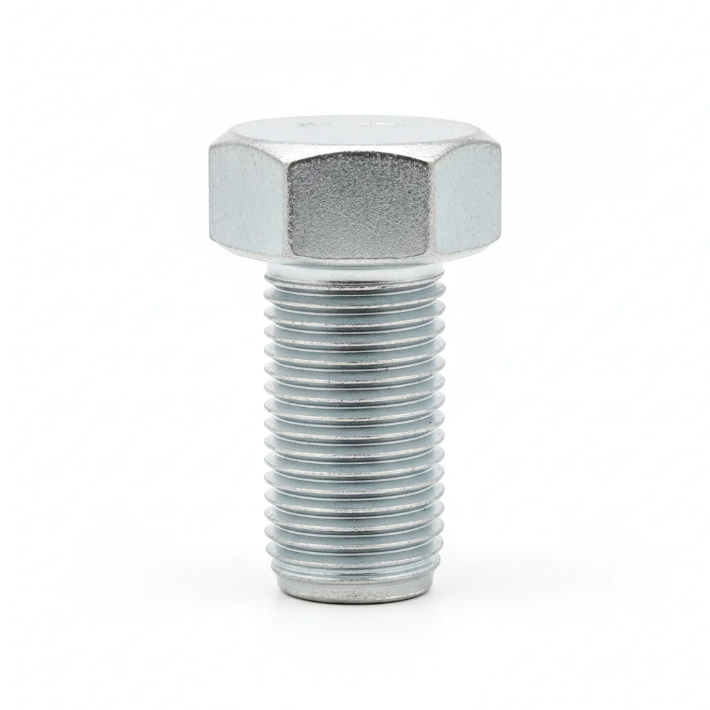
| Tin-Plated Copper Busbar | Insulation Spacer | Hex Bolt Kit | |
|---|---|---|---|
| SPEC | 30×5 ~ 80×10 mm | 3mm/5mm thick | M10×30 ~ M12×40 |
| MATERIAL | T2 Copper + Tin Plating ≥8μm | SMC/DMC | Carbon Steel Grade 8.8 + Galvanized |
| GRADE | — | — | 8.8 |
| FINISH | HDG >=55um per ISO 1461 | HDG >=55um per ISO 1461 | HDG >=55um per ISO 1461 |
| CORROSION | C3 (ISO 12944-2) | C3 (ISO 12944-2) | C3 (ISO 12944-2) |
| TEMP | -20°C to +80°C | -20°C to +80°C | -20°C to +80°C |
| WEIGHT | ~0.5 kg/piece | ~0.5 kg/piece | ~0.5 kg/piece |
| MOQ | 100 pcs | 100 pcs | 100 pcs |
| PACK | VCI paper + carton | VCI paper + carton | VCI paper + carton |
| STD | ISO 898-1, GB/T 3098.1 | ISO 898-1, GB/T 3098.1 | ISO 898-1, GB/T 3098.1 |
| USE | Main circuit conduction | Positive and negative pole isolation | Busbar lap joint fastening |
PROCEDURE
- Degrease the tin-plated busbar lap surface with isopropyl alcohol (99.9%) and confirm flatness within 0.1 mm per 100 mm before assembly.
- Apply a thin, even layer of joint compound to the contact area, then place the M10 or M12 grade 8.8 hex bolt with a Belleville washer under the head and nut.
- Align busbar sections within 0.5 mm, then tighten in a star pattern to the torque specified for the bolt size (e.g., M12 at 35 Nm) using a calibrated wrench; record values in the QA log.
- After torquing, measure contact resistance with a micro-ohmmeter to confirm it stays ≤10 μΩ per IEC 61439-1.
- Seat the SMC/DMC insulation spacer between positive and negative busbars, verify a minimum clearance of 30 mm, then mark bolt positions with torque seal paint and photograph the assembly for documentation.
COMMON ERRORS
| ✕ WRONG | CONSEQUENCE | ✓ CORRECT |
|---|---|---|
| Tightening M12 grade 8.8 bolts beyond the specified 35 Nm to 'make sure it's tight' | Over-torque can yield the bolt or crush the busbar, reducing clamping force over time and increasing contact resistance above the ≤10 μΩ limit. | Use a calibrated torque wrench set to the manufacturer's table value (e.g., M12 at 35 Nm) and verify with a micro-ohmmeter that contact resistance stays within spec. |
| Skipping the tin-plating check on incoming busbars, assuming all T2 copper is plated | Bare copper oxidizes quickly, pushing contact resistance from the design ≤10 μΩ up to 50–100 μΩ, causing voltage drop and localized heating. | Verify tin plating thickness ≥8 μm on the lap surface before installation; reject any material that does not meet this requirement. |
MAINTENANCE
Inspect busbar lap joints seasonally and at each overhaul window—re-torque any bolt that has lost more than 15% of its specified preload (e.g., below 80% of 35 Nm for M12), and replace bolts showing corrosion over 5% of surface area or pitting deeper than 0.3 mm. Every few years, disassemble a representative sample of joints to check for copper creep and re-apply joint compound as needed.
Plan B · Container Energy Storage Enhanced Type
C4 Harsh per ISO 12944-2
| Tin-Plated Copper Busbar | Insulation Spacer | Hex Bolt Kit | |
|---|---|---|---|
| SPEC | 30×5 ~ 80×10 mm | 3mm/5mm thick | M10×30 ~ M12×40 |
| MATERIAL | T2 Copper + Tin Plating ≥8μm | SMC/DMC | Carbon Steel Grade 8.8 + Galvanized |
| GRADE | — | — | 10.9 |
| FINISH | HDG >=55um per ISO 1461 | HDG >=55um per ISO 1461 | HDG >=55um per ISO 1461 |
| CORROSION | C3 (ISO 12944-2) | C3 (ISO 12944-2) | C3 (ISO 12944-2) |
| TEMP | -20°C to +80°C | -20°C to +80°C | -20°C to +80°C |
| WEIGHT | ~0.5 kg/piece | ~0.5 kg/piece | ~0.5 kg/piece |
| MOQ | 100 pcs | 100 pcs | 100 pcs |
| PACK | VCI paper + carton | VCI paper + carton | VCI paper + carton |
| STD | ISO 898-1, GB/T 3098.1 | ISO 898-1, GB/T 3098.1 | ISO 898-1, GB/T 3098.1 |
| USE | Main circuit conduction | Positive and negative pole isolation | Busbar lap joint fastening |
PROCEDURE
- Degrease the tin-plated copper busbar lap area with acetone and verify surface roughness Ra <3.2μm to ensure proper tin-to-tin contact for the 1600A rating.
- Apply a corrosion-inhibiting joint compound rated for -20°C to +150°C on the lap surfaces, then place the M12 grade 10.9 bolt with a PTFE-coated washer under the head and nut.
- Align the busbars within 0.5mm, then tighten in a cross-pattern sequence to the specified torque for grade 10.9 (per ISO 898-1) using a calibrated wrench; log torque values with ambient temperature and humidity.
- Pull-test 5% of installed bolts to 80% of proof load; replace any that slip or fail to meet the acceptance threshold.
- Apply a weatherproof protective coating over the bolt heads and exposed tin surfaces, and install a corrosion monitoring coupon adjacent to the highest-stressed lap joint for future inspection.
COMMON ERRORS
| ✕ WRONG | CONSEQUENCE | ✓ CORRECT |
|---|---|---|
| Using grade 8.8 bolts instead of the specified grade 10.9 for outdoor container service | Clamping force drops below the design value for 1600A, contact resistance exceeds 10μΩ, causing overheating and accelerated corrosion in the C4 environment. | Verify bolt grade markings before installation and use only grade 10.9 fasteners with the specified galvanized coating. |
| Skipping the application of corrosion-inhibiting compound on the tin-plated lap surfaces | Moisture ingress in the outdoor container leads to galvanic corrosion at the joint, increasing contact resistance and voltage drop within the first year. | Apply the specified compound evenly over the full lap area before assembly, ensuring coverage after tightening. |
MAINTENANCE
Inspect all busbar lap joints for torque loss and corrosion at each overhaul window or when the container is opened for service. Re-torque any bolt below 80% of the specified value; replace bolts showing corrosion over 5% of surface area or pitting depth >0.3mm. Perform a full disassembly and inspection of 20% of joints every 3 years, and replace all critical fasteners every 5 years regardless of condition. Document findings in CMMS with date and inspector ID; maximum allowable tension loss is 15%.
Plan C · Container Energy Storage Enhanced Type
C5-M Extreme per ISO 12944-2
| Tin-Plated Copper Busbar | Insulation Spacer | Hex Bolt Kit | Inspection & Maintenance Tool Kit | |
|---|---|---|---|---|
| SPEC | 30×5 ~ 80×10 mm | 3mm/5mm thick | M10×30 ~ M12×40 | Accessory |
| MATERIAL | T2 Copper + Tin Plating ≥8μm | SMC/DMC | Carbon Steel Grade 8.8 + Dacromet + Topcoat | — |
| GRADE | — | — | 12.9 | — |
| FINISH | HDG >=55um per ISO 1461 | HDG >=55um per ISO 1461 | HDG >=55um per ISO 1461 | HDG >=55um per ISO 1461 |
| CORROSION | C3 (ISO 12944-2) | C3 (ISO 12944-2) | C3 (ISO 12944-2) | C3 (ISO 12944-2) |
| TEMP | -20°C to +80°C | -20°C to +80°C | -20°C to +80°C | -20°C to +80°C |
| WEIGHT | ~0.5 kg/piece | ~0.5 kg/piece | ~0.5 kg/piece | ~0.5 kg/piece |
| MOQ | 100 pcs | 100 pcs | 100 pcs | 100 pcs |
| PACK | VCI paper + carton | VCI paper + carton | VCI paper + carton | VCI paper + carton |
| STD | ISO 898-1, GB/T 3098.1 | ISO 898-1, GB/T 3098.1 | ISO 898-1, GB/T 3098.1 | ISO 898-1, GB/T 3098.1 |
| USE | Main circuit conduction | Positive and negative pole isolation | Busbar lap joint fastening | Periodic torque verification |
PROCEDURE
- Degrease the silver-plated busbar lap area with MEK solvent and verify surface roughness Ra <1.6μm to ensure optimal conductivity for the 1600A rating.
- Apply a marine-grade anti-corrosion compound rated for -50°C to +200°C on the lap surfaces, then install the M12 grade 12.9 bolt with PTFE-encapsulated washers under head and nut.
- Align the busbars within 0.3mm, then tighten using a hydraulic tensioner to achieve the precise preload required for grade 12.9 (per ISO 898-1). PMI-verify 10% of bolts to confirm material grade and document for compliance audit.
- Perform dye penetrant NDT on 10% of the installed bolts; replace any showing crack indications before energizing.
- Apply a protective sealant over the entire joint area and install permanent condition monitoring sensors to track bolt tension and joint temperature in real time.
COMMON ERRORS
| ✕ WRONG | CONSEQUENCE | ✓ CORRECT |
|---|---|---|
| Substituting grade 10.9 bolts for the specified grade 12.9 in a C5-M marine environment | Insufficient clamping force leads to vibration-induced loosening during container transport, increasing contact resistance and risking thermal runaway in the energy storage system. | Use only grade 12.9 bolts with Dacromet plus topcoat finish; verify via PMI testing before installation. |
| Omitting the PTFE-encapsulated washers that electrically isolate the bolt from the busbar | Galvanic corrosion between the bolt and the busbar accelerates in the salt-laden C5-M atmosphere, degrading joint integrity within months. | Always install the specified PTFE-encapsulated washers under both head and nut to prevent bimetallic contact. |
MAINTENANCE
Inspect all busbar lap joints for torque loss, corrosion, and sealant integrity at each overhaul window or quarterly in aggressive coastal environments. Re-torque any bolt below 80% of the specified value; replace bolts with corrosion over 5% of surface area or pitting depth >0.3mm. Perform full disassembly and inspection of 20% of joints every 3 years, and replace all critical fasteners every 5 years regardless of condition. Use condition monitoring data to schedule maintenance proactively; maximum allowable tension loss is 15%.
REFERENCED STANDARDS
Technical Basis and Reference Standards
Copper, aluminum and their alloy busbars for electrical purposes
Safety requirements for industrial batteriesLow-voltage switchgear and controlgear assemblies
Low-voltage switchgearLow-voltage switchgear and controlgear
Energy storage safety standardCopper and copper alloy busbars Part 2
Low-voltage switchgear assembliesLow-voltage switchgear and controlgear
SUPPLIER CAPABILITY
Quality, Delivery & Customization
Quality Control
- ✓MTC material certificates with every batch
- ✓Key parts sampled for hardness/salt spray/torque coefficient
- ✓100% inspection or AQL sampling before shipment
Delivery
- ✓Standard parts made to order: 7-15 days
- ✓Custom parts: 25-45 days
- ✓FOB/CIF/DDP supported
Customization
- ✓Drawing review and material matching
- ✓Non-standard sizes/heads/threads
- ✓Small-batch prototyping supported
Certification
- ✓Material certificates (MTC)
- ✓Spectrographic analysis reports
- ✓Salt spray test reports (on request)
MOQ: No MOQ for standard parts; custom parts assessed by process complexity
FAQ
Frequently Asked Questions
RELATED READING
Keep Reading & Next Step
BEYOND TECHNICAL SPECS
Finding the right factory, controlling quality, delivering on time — that's the real challenge. We cover fasteners, rubber, plastics, industrial textiles. One team, end to end.
SEE CAPABILITIES →