
Battery Rack Fasteners: Insulated Bolts vs Disc Spring Washers
ESS rack fastening has two different risks: electrical isolation around battery modules and clamp-load retention under vibration or thermal movement. The bolt, washer and coating package should be specified as one hardware system
RISK AUDIT // ENGINEERING DIAGNOSIS
Purchasing Pitfall Guide
"Field failures in ESS racks often trace back to a single overlooked interface: the bolt that both isolates and clamps."
QC-AUDIT // REV.5
SCALE 1:1 · 03 ITEMS
RISK-01
Battery Rack Insulation Failure Leading to DC Leakage
Corrective Measures
RISK-02
High Sealing Requirements for Thermal Management Systems
Corrective Measures
RISK-03
Busbar Connection Heating Risk
Corrective Measures
FIELD-SPECIFIC INSIGHT
Separate Insulation Risk from Clamp-Load Risk
Lee Spring's Belleville washer guidance describes vibration, thermal expansion, relaxation and bolt creep as reasons to use disc spring washers. In ESS racks, this does not replace insulation checks; it adds a separate fastener requirement
WHAT TO CHECK
- 1Use insulated bolts or sleeves where the joint must control electrical isolation
- 2Use disc spring washers where the joint must maintain clamping force under movement or relaxation
- 3Do not let coating choice hide the insulation requirement; coating and isolation are different checks
- 4Ask for supplier documents that show washer type, bolt grade, coating and installation sequence together
| Check | Why it matters | What to specify |
|---|---|---|
| Electrical isolation | A mechanically tight joint can still be wrong if it creates an unintended conductive path | Insulated bolt, sleeve, washer stack and required test document |
| Clamp-load retention | Thermal movement and relaxation can reduce preload even when the initial torque was correct | Disc spring washer type, preload method and inspection routine |
| Coating compatibility | Coating affects corrosion protection, friction and washer behavior at the same joint | Bolt coating, washer coating and whether torque values are based on that surface condition |
Supplier washer guidance supports the function of disc springs; project insulation and torque values still need project or supplier verification
Evidence level: source-page-only
INDUSTRY TECH REFERENCE
Rack Fixing Points: Scheme, Size, and Inspection Cycle
Rack fixing splits into three schemes by location, each with its own size range and inspection cycle — verify acceptance against this table.
| Fixing point | Scheme | Size | Key parameters | Inspection cycle |
|---|---|---|---|---|
| Module fixing bolts | 304 SS + nylon insulation washers, to prevent accidental contact with busbars | M8–M12 | Allow clearance for LFP cycling expansion (~3–5%); creepage distance per IEC 61439 tiers | Yearly |
| Rack anchor bolts | Epoxy chemical anchors instead of expansion bolts — better seismic and thermal-cycling behavior | M12–M16 | M16 nominal torque ≈160 N·m; preload decays 5–8% per year under thermal cycling | Semi-annual |
| Anti-loosening | Double nuts / nylon lock nuts + wedge locking washers | Match bolt size | Used together with the fixing points above | With fixing point |
"LFP cycling expansion ~3–5%" and "preload decay 5–8%/yr" are magnitude estimates from engineering literature.
INDUSTRY TECH REFERENCE
Thermal Cycling Drains Preload Year by Year — Will It Withstand a Quake?
Example: rack anchor bolts M12–M16 with epoxy chemical anchors in a seismic zone (Japan, California, Chile).
- 1Charge/discharge thermal cycling makes the rack expand and contract within 20–55°C
- 2Expansion and contraction drain anchor preload by about 5–8% per year (magnitude estimate)
- 3Joint stiffness drops and module fixing points start to loosen
- 4In seismic zones, verify per IEEE 693: module fixing bolts need a shear safety factor ≥4 (recommended)
- 5With insufficient preload, shear limits are exceeded and modules shift — use epoxy chemical anchors instead of expansion bolts and retorque every six months
"Preload decay 5–8%/yr" is a magnitude estimate; shear safety factor ≥4 is a recommended value.
INDUSTRY TECH REFERENCE
Anti-Loosening Options: Washers, Lock Nuts, and Anchors
Match three part families to the fixing point instead of relying on initial torque alone.
- Module fixing: 304 SS bolts + nylon insulation washers, with double nuts or nylon lock nuts for loosening resistance
- Anchors: epoxy chemical anchors instead of expansion bolts — better seismic and thermal-cycling performance
- High-temperature or vibration-prone points: wedge locking washers, used with the schemes above
- Discipline: retorque anchors every six months; check module fixing bolts yearly
SELECTION GUIDE
Rack Fastener Decision Guide
| Operating condition | Recommended option | Key basis |
|---|---|---|
| Joint must control electrical isolation (battery module fixation, 500-1500V DC system) | Insulated bolt/sleeve stack with polycarbonate or epoxy washer (withstand voltage ≥2kV) | UL 1973 (insulation resistance ≥100kΩ for a 1000V system) |
| Joint must retain clamp load under vibration and thermal movement | Belleville disc spring washer (51CrV4, compensates 0.2-0.5mm thermal deformation) | IEC 62619 / GB/T 36276 (energy storage battery safety) |
| Liquid cooling pipe fitting with high sealing requirement | 304/316L stainless ferrule fitting with EPDM sealing ring; pressure test at 1.5× working pressure | UL 1973 / IEC 62619 |
| Copper busbar connection point heating risk | Tin-plate busbar surface, install with recommended torque, regular infrared temperature inspection | GB/T 36276 |
| Anti-corrosion and protection environment C3/C4 (ISO 12944-2) | Specify bolt coating and washer coating jointly; coating and insulation are separate acceptance checks | ISO 12944-2 |
① Insulated Bolt
C3 per ISO 12944-2; insulation rated for 1500VDC, flame retardant V0 (UL94)
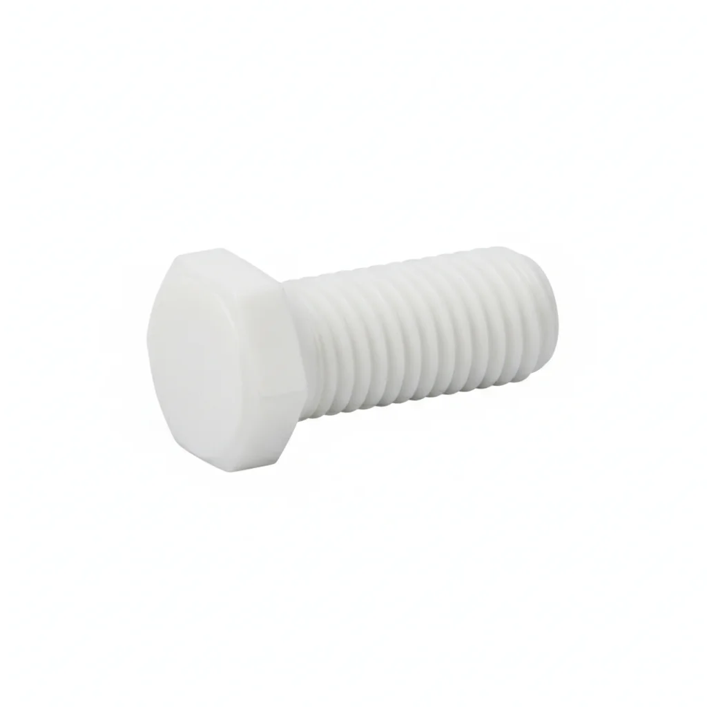
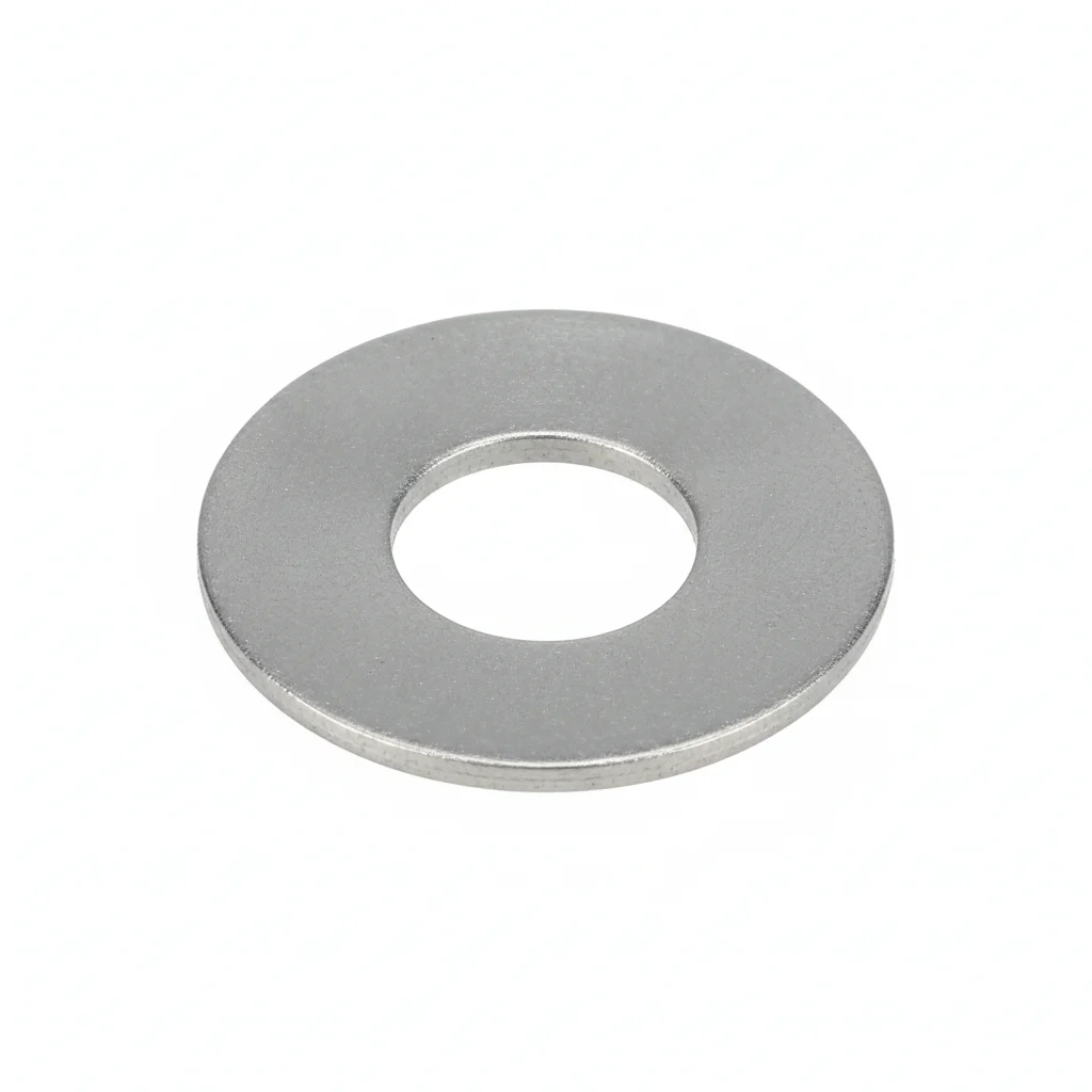
| Insulated Bolt | Insulated Bolt (Large) | Flat Washer | |
|---|---|---|---|
| SPEC | M8×25, Withstand Voltage 1500VDC | M12×40, Withstand Voltage 2000VDC | M10-M12 |
| MATERIAL | PA66+GF30% | PA66+GF30% | 304 Stainless |
| GRADE | V0 | V0 | A2 |
| FINISH | HDG >=55um per ISO 1461 | HDG >=55um per ISO 1461 | Passivated |
| CORROSION | C3 (ISO 12944-2) | C3 (ISO 12944-2) | C3 (ISO 12944-2) |
| TEMP | -20°C to +80°C | -20°C to +80°C | -20°C to +80°C |
| WEIGHT | ~0.5 kg/piece | ~0.5 kg/piece | ~0.005kg |
| MOQ | 100 pcs | 100 pcs | 500 pcs |
| PACK | VCI paper + carton | VCI paper + carton | Plastic bag |
| STD | ISO 898-1, GB/T 3098.1 | ISO 898-1, GB/T 3098.1 | ISO 7089 |
| USE | Battery Pack Fixation | Container Energy Storage Module Fixation | Load distribution |
PROCEDURE
- Degrease the aluminum rack rail and module mounting face with isopropyl alcohol; confirm the PA66+GF30% insulated bolt and flat washer are free of dust or moisture before assembly.
- Position the M8×25 insulated bolt through the module bracket and rack rail, placing the 304 stainless flat washer (ISO 7089) under the head to spread the clamp load over the composite surface.
- Hand-start the nut, then tighten in a star pattern using a calibrated torque wrench to the 2-8 N·m range specified for the M6-M16 insulated bolt series.
- After reaching target torque, verify that no metallic path bridges the module to the rack using a 1500VDC withstand test or insulation resistance check per the project's QA plan.
- Mark each torqued bolt head with a paint stripe and log the torque value and operator ID in the assembly record.
COMMON ERRORS
| ✕ WRONG | CONSEQUENCE | ✓ CORRECT |
|---|---|---|
| Reusing a PA66+GF30% insulated bolt that has been over-torqued beyond its elastic range | Micro-cracks in the glass-filled nylon can reduce dielectric strength, risking DC leakage or creepage failure at the 1500VDC system voltage. | Discard any insulated bolt that was over-torqued or dropped; install a new M8×25 bolt and re-torque within the specified 2-8 N·m window. |
| Tightening the insulated bolt without the 304 stainless flat washer | The PA66+GF30% head can embed into the module bracket, reducing clamp load and allowing vibration loosening that may also chafe the insulation layer. | Always fit the ISO 7089 flat washer under the head (and nut if specified) to distribute load and protect the composite material. |
MAINTENANCE
At each scheduled rack inspection (seasonally or per the ESS maintenance window), check insulated bolts for visible cracks, discoloration, or dust bridging on the PA66+GF30% surface. Verify that no metallic debris or conductive contamination has reduced the creepage distance. Confirm the flame-retardant V0 rating is intact by inspecting for charring or melting near the bolt head. Re-torque any bolt that has loosened beyond the 2-8 N·m range, and replace any bolt with signs of surface degradation or dielectric stress.
② Belleville Disc Spring
C3 (ISO 12944-2) with thermal cycling -20°C to +80°C
| Disc Spring | Flat Washer | Flat Washer | |
|---|---|---|---|
| SPEC | D25mm, Load 2000N | M10-M12 | M10-M12 |
| MATERIAL | 51CrV4 | 304 Stainless | 304 Stainless |
| GRADE | — | A2 | A2 |
| FINISH | HDG >=55um per ISO 1461 | Passivated | Passivated |
| CORROSION | C3 (ISO 12944-2) | C3 (ISO 12944-2) | C3 (ISO 12944-2) |
| TEMP | -20°C to +80°C | -20°C to +80°C | -20°C to +80°C |
| WEIGHT | ~0.5 kg/piece | ~0.005kg | ~0.005kg |
| MOQ | 100 pcs | 500 pcs | 500 pcs |
| PACK | VCI paper + carton | Plastic bag | Plastic bag |
| STD | ISO 898-1, GB/T 3098.1 | ISO 7089 | ISO 7089 |
| USE | Battery Pack Bolt Compensation | Load distribution | Load distribution |
PROCEDURE
- Clean mating surfaces with acetone to remove oil and debris; ensure roughness Ra <3.2μm for proper disc spring seating.
- Place the 51CrV4 disc spring (D25mm, load 2000N) over the bolt, oriented correctly per the load-deflection curve to compensate 0.2-0.5mm thermal expansion.
- Stack flat washers (304 stainless, M10-M12) on both sides of the joint to distribute load and prevent galling on the aluminum rack surface.
- Hand-tighten the nut, then use a calibrated torque wrench to reach the specified preload (within the disc spring's working range) — do not over-compress the spring.
- Verify deflection of the disc spring using a feeler gauge or dial indicator; confirm it stays within the designed 0.2-0.5mm compensation range.
- Mark the final position with torque seal paint and record the assembly data (torque, deflection, ambient temperature) in the QA log.
COMMON ERRORS
| ✕ WRONG | CONSEQUENCE | ✓ CORRECT |
|---|---|---|
| Installing the disc spring upside down or with the wrong orientation | Reduced load capacity and incorrect deflection direction, leading to loss of clamp load under thermal cycling. | Refer to the disc spring drawing to confirm the concave/convex orientation matches the load direction. |
| Using a plain washer instead of the specified 304 stainless flat washer between the disc spring and the aluminum surface | Galvanic corrosion between the 51CrV4 spring and aluminum, causing surface pitting and loss of preload over time. | Always use the 304 stainless flat washer (M10-M12) on both sides of the joint to isolate dissimilar metals. |
| Overtightening the bolt to a torque beyond the disc spring's rated load (e.g., ignoring the 2000N limit) | Flattening the disc spring (over-compression), reducing its ability to compensate for thermal expansion and causing premature relaxation. | Torque to the specified preload that keeps the disc spring within its linear deflection range; use a torque wrench with +/-3% accuracy. |
MAINTENANCE
Inspect disc spring assemblies at each maintenance window (seasonally or after thermal events) for signs of corrosion, cracking, or set. Verify that the spring deflection is still within the 0.2-0.5mm compensation range; if loss of preload is suspected, re-torque to specification. Replace any disc spring showing pitting deeper than 0.3mm or corrosion affecting more than 5% of surface area. At each major overhaul (e.g., every 5 years per ISO 12944-2), replace disc springs and 304 washers regardless of condition to ensure continued thermal compensation.
REFERENCED STANDARDS
Technical Basis and Reference Standards
Energy Storage System Safety Standard
Safety Requirements for Industrial BatteriesIndustrial Lithium Battery Safety Requirements
Seismic Design of SubstationsPlastic Flame Retardancy Grade
Energy Storage System SafetyMechanical Properties of Fasteners - Bolts, Screws and Studs
Energy Storage System SpecificationCorrosion Tests in Artificial Atmospheres - Salt Spray Tests
SUPPLIER CAPABILITY
Quality, Delivery & Customization
Quality Control
- ✓MTC material certificates with every batch
- ✓Key parts sampled for hardness/salt spray/torque coefficient
- ✓100% inspection or AQL sampling before shipment
Delivery
- ✓Standard parts made to order: 7-15 days
- ✓Custom parts: 25-45 days
- ✓FOB/CIF/DDP supported
Customization
- ✓Drawing review and material matching
- ✓Non-standard sizes/heads/threads
- ✓Small-batch prototyping supported
Certification
- ✓Material certificates (MTC)
- ✓Spectrographic analysis reports
- ✓Salt spray test reports (on request)
MOQ: No MOQ for standard parts; custom parts assessed by process complexity
FAQ
Frequently Asked Questions
RELATED READING
Keep Reading & Next Step
BEYOND TECHNICAL SPECS
Finding the right factory, controlling quality, delivering on time — that's the real challenge. We cover fasteners, rubber, plastics, industrial textiles. One team, end to end.
SEE CAPABILITIES →