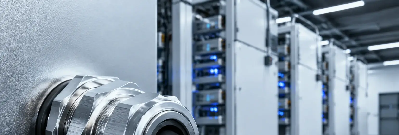
Cable Gland Seal Failure in Energy Storage: Over-Tightening and EMC Risks
Each energy storage cabinet has 10-30 cable entry holes. Gland seal failure from over-tightening or improper EMC grounding can cause water ingress, insulation damage, and BMS communication errors. A single gland costs tens of yuan, but repair of a water-damaged battery module can cost thousands. This page explains the failure chain and key procurement checks
RISK AUDIT // ENGINEERING DIAGNOSIS
Procurement Pitfall Guide
"Two overlooked mistakes—overtightening and poor EMC grounding—are behind most gland failures in storage cabinets."
QC-AUDIT // REV.5
SCALE 1:1 · 03 ITEMS
RISK-01
Cable Insulation Damage Due to Over-Tightening of Gland
Corrective Measures
RISK-02
Standard Glands Do Not Meet EMC Requirements
Corrective Measures
RISK-03
Communication Interference Due to Poor Gland EMC Grounding
Corrective Measures
FIELD-SPECIFIC INSIGHT
Cable Gland Failure Chain: Over-Tightening and EMC Grounding
Cable gland failures in energy storage often stem from two overlooked issues: over-tightening that damages cable insulation, and poor EMC grounding that disrupts BMS communication. Both can be prevented with proper torque control and shielded gland selection
WHAT TO CHECK
- 1Over-tightening beyond recommended torque (e. G. , PG11 at 3-4 Nm) compresses the sealing cone, reducing cable cross-section >5% and causing micro-cracks after thermal cycling
- 2Standard non-EMC glands interrupt cable shielding, creating an 'antenna gap' that couples electromagnetic noise into BMS signal lines
- 3Insufficient gland tightening (<5 Nm) or paint on mounting holes increases contact resistance >10 mΩ, degrading EMC shielding and causing BMS communication bit errors
- 4IEC 62444 requires tightening torque to be stated in the manual; installation without a torque tool is unacceptable
| Check | Why it matters | What to specify |
|---|---|---|
| Tightening torque | Over-torque damages cable insulation; under-torque compromises sealing and EMC grounding | Specify torque value per gland size (e. G. , PG11: 3-4 Nm) and require torque tool use during installation |
| EMC shielding continuity | Non-shielded glands interrupt cable shield, causing BMS communication errors | Use shielded cable glands for signal cables; ensure contact resistance <10 mΩ via proper grounding |
| Gland material and environment | Nylon glands degrade outdoors; 316L resists corrosion in coastal/offshore environments | Select material per ISO 12944-2 corrosivity category (C3 indoor nylon, C4 outdoor 316L, C5-M offshore 316L/duplex) |
Tightening torque values and contact resistance limits should be verified with the gland manufacturer's datasheet
Evidence level: standard-backed
INDUSTRY TECH REFERENCE
What Cable-Entry Sealing Must Withstand
Cable entries are the weakest point of cabinet sealing — the gland and its sealing ring are the only barrier.
"~2-year carbon-steel corrosion" is a magnitude estimate.
INDUSTRY TECH REFERENCE
What to Check During Inspection
Routine inspection of glands, sealing rings, and strip retainers.
- Check glands are tight and sealing rings are not extruded or off-center; before the rainy season, check the door sealing face for condensation
- Retainer nail spacing no more than 150 mm; add nails immediately where bulging appears — bulging is where leaks start
- All exterior hardware in 304 (fewer than 100 pieces per cabinet, limited cost); hinge bolts M8–M10 — replace at the first sign of rust, don't wait for the door to sag
PLAN COMPARISON
Three-Plan Core Parameter Comparison
Compare row by row. Click column headers to jump to plan details.
| A · Plan A · General Purpose Nylon Cable Gland | B · Plan B · 316L Stainless Steel Reinforced | C · Plan C · Extreme Environment / Offshore Configuration | |
|---|---|---|---|
| 1. NYLON CABLE GLAND | |||
| SPEC | PG7-PG21 | M16-M63 | M16-M63 |
| MATERIAL | PA66+EPDM | 316L+EPDM | 316L |
| GRADE | IP68 | IP69K | ATEX/IECEx |
| FINISH | HDG >=55um per ISO 1461 | HDG >=55um per ISO 1461 | HDG >=55um per ISO 1461 |
| 2. FLAT WASHER | |||
| SPEC | M10-M12 | M10-M12 | M16-M50 |
| MATERIAL | 304 Stainless | 304 Stainless | 316L+Spring Fingers |
| GRADE | A2 | A2 | EMC Shielded |
| FINISH | Passivated | Passivated | HDG >=55um per ISO 1461 |
| 3. FLAT WASHER | |||
| SPEC | M10-M12 | M10-M12 | PG7-PG21 |
| MATERIAL | 304 Stainless | 304 Stainless | EPDM Rubber |
| GRADE | A2 | A2 | Chemical Resistant |
| FINISH | Passivated | Passivated | HDG >=55um per ISO 1461 |
| 4. FLAT WASHER | |||
| SPEC | M10-M12 | M10-M12 | M20-M40 |
| MATERIAL | 304 Stainless | 304 Stainless | EPDM Rubber |
| GRADE | A2 | A2 | IP69K |
| FINISH | Passivated | Passivated | HDG >=55um per ISO 1461 |
| 5. FLAT WASHER | |||
| SPEC | M10-M12 | M10-M12 | Compatible PG7-M63 |
| MATERIAL | 304 Stainless | 304 Stainless | — |
| GRADE | A2 | A2 | — |
| FINISH | Passivated | Passivated | HDG >=55um per ISO 1461 |
SELECTION GUIDE
Still not sure which gland plan fits your site?
| Operating condition | Recommended option | Key basis |
|---|---|---|
| Indoor energy storage / general outdoor | Plan A · General Purpose Nylon Cable Gland: PA66+EPDM (PG7-PG21, IP68) | IEC 62444; ISO 12944-2 (C3) |
| Outdoor / coastal | Plan B · 316L Stainless Steel Reinforced: 316L+EPDM (M16-M63, IP69K) | IEC 62444; ISO 12944-2 (C4) |
| Offshore platform / C5-M environment / highest protection requirements | Plan C · Extreme Environment/Offshore Configuration: explosion-proof cable gland (316L, ATEX/IECEx), EMC shielded gland (316L+spring fingers, M16-M50), chemical-resistant sealing gland (EPDM), double seal gland (IP69K) | IEC 60079; GB 3836; ISO 12944-2 (C5-M) |
| BMS signal cables / EMC-sensitive circuits | Use EMC shielded glands (360° spring-finger contact with cable shield); shield contact resistance <10mΩ; grind 10mm bare-metal area around the mounting hole, torque 8-12Nm; route communication cables separately from power cables | IEC 62444 (gland standard) |
| Gland installation (prevent over-tightening damage) | Use a torque wrench at the recommended torque per gland size (e.g., PG11: 3-4Nm); caliper-check the cable diameter at the gland outlet, reduction <3% acceptable | IEC 62444 (tightening torque stated in manual) |
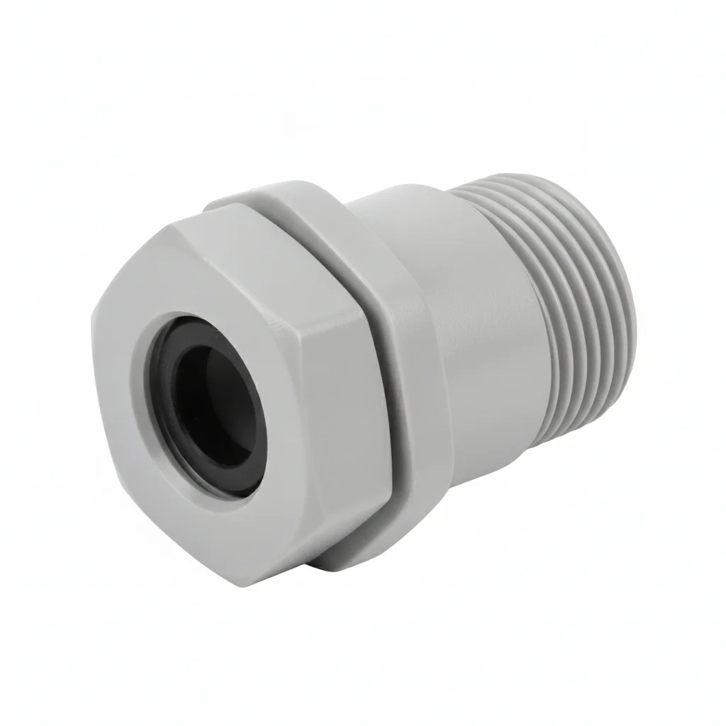
Plan A · General Purpose Nylon Cable Gland
C3 (ISO 12944-2) indoor/general outdoor with IP68 protection
| Nylon Cable Gland | Flat Washer | Flat Washer | Flat Washer | Flat Washer | |
|---|---|---|---|---|---|
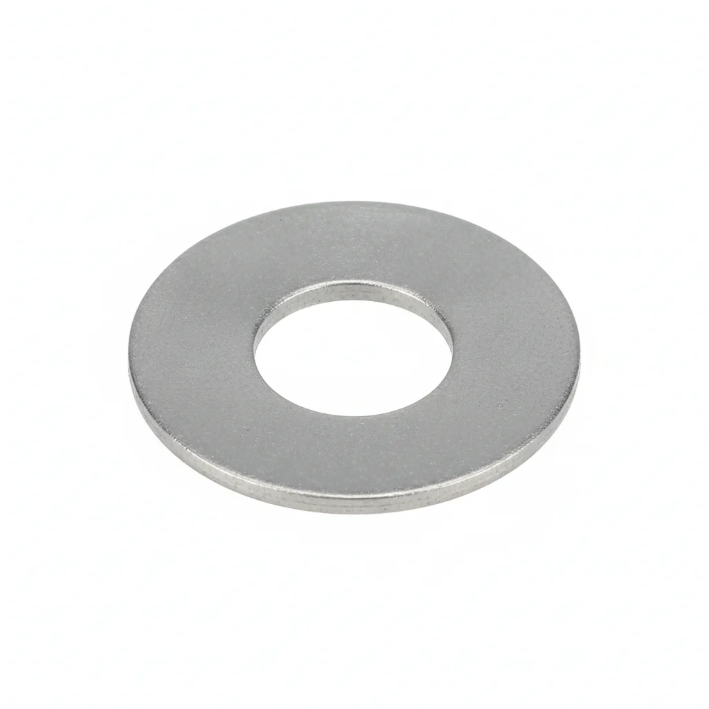
| SPEC | PG7-PG21 | M10-M12 | M10-M12 | M10-M12 | M10-M12 |
| MATERIAL | PA66+EPDM | 304 Stainless | 304 Stainless | 304 Stainless | 304 Stainless |
| GRADE | IP68 | A2 | A2 | A2 | A2 |
| FINISH | HDG >=55um per ISO 1461 | Passivated | Passivated | Passivated | Passivated |
| CORROSION | C3 (ISO 12944-2) | C3 (ISO 12944-2) | C3 (ISO 12944-2) | C3 (ISO 12944-2) | C3 (ISO 12944-2) |
| TEMP | -20°C to +80°C | -20°C to +80°C | -20°C to +80°C | -20°C to +80°C | -20°C to +80°C |
| WEIGHT | ~0.5 kg/piece | ~0.005kg | ~0.005kg | ~0.005kg | ~0.005kg |
| MOQ | 100 pcs | 500 pcs | 500 pcs | 500 pcs | 500 pcs |
| PACK | VCI paper + carton | Plastic bag | Plastic bag | Plastic bag | Plastic bag |
| STD | ISO 898-1, GB/T 3098.1 | ISO 7089 | ISO 7089 | ISO 7089 | ISO 7089 |
| USE | General Cable Entry | Load distribution | Load distribution | Load distribution | Load distribution |
PROCEDURE
- Clean the cable entry area and ensure the cable jacket is free of moisture and debris.
- Slide the gland components onto the cable in the correct order (locknut, body, seal, washer).
- Insert the cable into the gland and hand-tighten the cap until snug.
- Using a torque wrench, tighten the gland cap to the recommended torque per IEC 62444 (e.g., PG11: 3–4 Nm).
- Verify the cable is secure and measure the outer diameter at the gland outlet to ensure reduction <3%.
COMMON ERRORS
| ✕ WRONG | CONSEQUENCE | ✓ CORRECT |
|---|---|---|
| Over-tightening the gland beyond the recommended torque (e.g., 5–6 Nm for PG11) | Sealing cone over-compresses, causing cable insulation 'waist' and cross-section reduction >5%, leading to micro-cracks and insulation failure. | Use a torque wrench set to the gland's specified torque (e.g., PG11: 3–4 Nm) as per IEC 62444. |
| Using a standard (non-EMC) gland for BMS signal cables | Cable shield is interrupted, creating an 'antenna gap' that couples electromagnetic noise into signal lines, causing BMS communication errors. | Select EMC shielded glands with 360° spring fingers for signal cables to maintain shield continuity and contact resistance <10 mΩ. |
MAINTENANCE
Inspect glands at each system maintenance window (e.g., during scheduled battery checks) for signs of cracking or loosening. Re-torque to specified values if loosened. Replace any gland showing UV embrittlement (nylon) or seal deformation. Verify EMC shield contact resistance remains <10 mΩ per IEC 62444.
Plan B · 316L Stainless Steel Reinforced
C4 Harsh per ISO 12944-2
| Cable Gland | Flat Washer | Flat Washer | Flat Washer | Flat Washer | |
|---|---|---|---|---|---|
| SPEC | M16-M63 | M10-M12 | M10-M12 | M10-M12 | M10-M12 |
| MATERIAL | 316L+EPDM | 304 Stainless | 304 Stainless | 304 Stainless | 304 Stainless |
| GRADE | IP69K | A2 | A2 | A2 | A2 |
| FINISH | HDG >=55um per ISO 1461 | Passivated | Passivated | Passivated | Passivated |
| CORROSION | C3 (ISO 12944-2) | C3 (ISO 12944-2) | C3 (ISO 12944-2) | C3 (ISO 12944-2) | C3 (ISO 12944-2) |
| TEMP | -20°C to +80°C | -20°C to +80°C | -20°C to +80°C | -20°C to +80°C | -20°C to +80°C |
| WEIGHT | ~0.5 kg/piece | ~0.005kg | ~0.005kg | ~0.005kg | ~0.005kg |
| MOQ | 100 pcs | 500 pcs | 500 pcs | 500 pcs | 500 pcs |
| PACK | VCI paper + carton | Plastic bag | Plastic bag | Plastic bag | Plastic bag |
| STD | ISO 898-1, GB/T 3098.1 | ISO 7089 | ISO 7089 | ISO 7089 | ISO 7089 |
| USE | Harsh Outdoor Environment | Load distribution | Load distribution | Load distribution | Load distribution |
PROCEDURE
- Clean the cabinet mounting hole with a wire brush to bare metal, ensuring a conductive path for EMC grounding.
- Slide the 316L cable gland over the cable, positioning the EPDM sealing ring correctly.
- Hand-tighten the gland until snug, then use a torque wrench to apply the recommended torque (e.g., PG11: 3-4 Nm). Do not exceed the specified range.
- Verify the cable insulation is not deformed at the gland outlet; measure with a caliper to ensure cross-section reduction is less than 3%.
- For signal cables, use shielded glands with spring fingers; confirm 360° contact and measure contact resistance below 10 mΩ.
- Apply anti-seize compound on threads for coastal environments to prevent galling.
COMMON ERRORS
| ✕ WRONG | CONSEQUENCE | ✓ CORRECT |
|---|---|---|
| Using a wrench to tighten the gland beyond the recommended torque (e.g., 5-6 Nm for PG11) to ensure a 'tight' seal. | Over-compression of the sealing cone creates a 'waist' in the cable insulation, reducing cross-section by >5%, leading to micro-cracks and insulation failure after thermal cycling. | Always use a torque wrench set to the manufacturer's specified torque (e.g., PG11: 3-4 Nm) and verify cable diameter after installation. |
| Leaving paint or corrosion on the mounting hole surface when installing a shielded gland. | Contact resistance rises above 10 mΩ, breaking EMC shield continuity and causing BMS communication errors. | Grind a 10mm area around the hole to bare metal to ensure 360° conductive contact. |
MAINTENANCE
Inspect glands at each overhaul window (e.g., during scheduled maintenance) for signs of corrosion or loosening. Re-torque if loosened. Replace any gland with visible corrosion pitting or damaged seal.
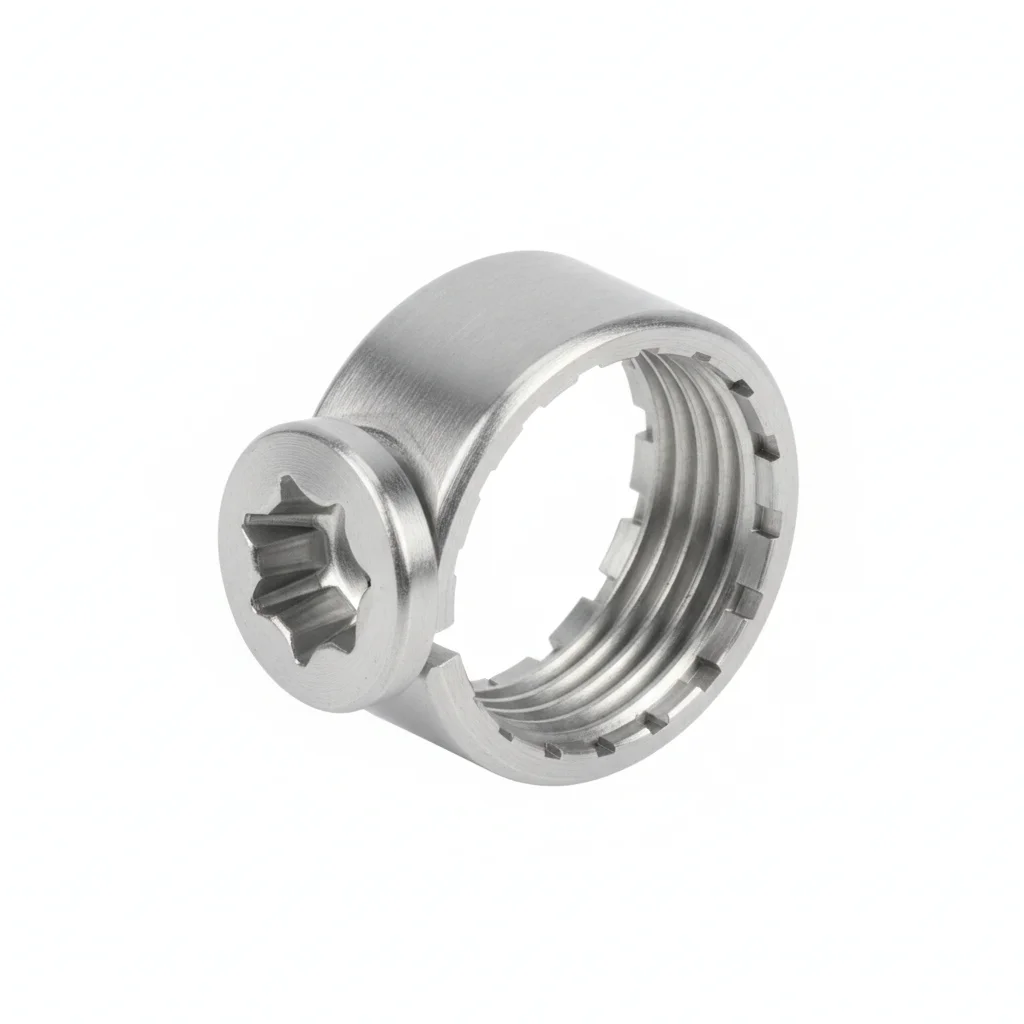
Plan C · Extreme Environment / Offshore Configuration
C5-M Extreme per ISO 12944-2
| Explosion-Proof Cable Gland | Shielded Cable Gland | Sealing Gland | Double Seal Gland | Gland Torque Wrench | |
|---|---|---|---|---|---|
| SPEC | M16-M63 | M16-M50 | PG7-PG21 | M20-M40 | Compatible PG7-M63 |
| MATERIAL | 316L | 316L+Spring Fingers | EPDM Rubber | EPDM Rubber | — |
| GRADE | ATEX/IECEx | EMC Shielded | Chemical Resistant | IP69K | — |
| FINISH | HDG >=55um per ISO 1461 | HDG >=55um per ISO 1461 | HDG >=55um per ISO 1461 | HDG >=55um per ISO 1461 | HDG >=55um per ISO 1461 |
| CORROSION | C3 (ISO 12944-2) | C3 (ISO 12944-2) | Not applicable (polymer) | Not applicable (polymer) | C3 (ISO 12944-2) |
| TEMP | -20°C to +80°C | -20°C to +80°C | -20°C to +80°C | -20°C to +80°C | -20°C to +80°C |
| WEIGHT | ~0.5 kg/piece | ~0.5 kg/piece | ~0.5 kg/piece | ~0.5 kg/piece | ~0.5 kg/piece |
| MOQ | 100 pcs | 100 pcs | 100 pcs | 100 pcs | 100 pcs |
| PACK | VCI paper + carton | VCI paper + carton | VCI paper + carton | VCI paper + carton | VCI paper + carton |
| STD | ISO 898-1, GB/T 3098.1 | ISO 898-1, GB/T 3098.1 | ISO 898-1, GB/T 3098.1 | ISO 898-1, GB/T 3098.1 | ISO 898-1, GB/T 3098.1 |
| USE | Explosion-Proof Energy Storage Cabinet | BMS Signal Cables | Chemical Energy Storage Cabinet | Harsh Outdoor Environment | Ensures Accurate Installation Torque |
PROCEDURE
- Prepare the mounting surface by grinding to bare metal and cleaning with degreaser to ensure proper EMC contact.
- Select the appropriate explosion-proof gland (ATEX/IECEx) for hazardous areas; verify certification matches the zone classification.
- Install the gland with the included torque wrench, tightening to the specified torque for the gland size (e.g., PG11: 3-4 Nm). For EMC glands, ensure spring fingers align with the cable shield.
- Check that the cable insulation is not compressed beyond acceptable limits (cross-section reduction <3%) using a caliper.
- For signal cables, confirm contact resistance is below 10 mΩ with a micro-ohmmeter to ensure shielding effectiveness.
- Apply protective sealant around the gland entry to prevent moisture ingress in offshore environments.
COMMON ERRORS
| ✕ WRONG | CONSEQUENCE | ✓ CORRECT |
|---|---|---|
| Using a standard (non-EMC) gland for BMS signal cables in a high-interference environment. | The cable shield is interrupted, creating an 'antenna gap' that couples electromagnetic noise, causing BMS communication errors or data corruption. | Use shielded glands with internal spring fingers for 360° shield contact and verify contact resistance <10 mΩ. |
| Over-tightening the gland beyond the recommended torque to achieve a 'better' seal, especially on explosion-proof glands. | Over-compression damages the cable insulation, leading to insulation failure and potential short circuits, compromising safety in explosive atmospheres. | Use a torque wrench set to the specified value (e.g., PG11: 3-4 Nm) and follow the manufacturer's instructions. |
MAINTENANCE
Inspect glands during each scheduled maintenance window for corrosion, seal degradation, or loosening. Replace any gland showing signs of cracking or loss of sealing integrity. Verify EMC contact resistance annually.
REFERENCED STANDARDS
References
SUPPLIER CAPABILITY
Quality, Delivery & Customization
Quality Control
- ✓MTC material certificates with every batch
- ✓Key parts sampled for hardness/salt spray/torque coefficient
- ✓100% inspection or AQL sampling before shipment
Delivery
- ✓Standard parts made to order: 7-15 days
- ✓Custom parts: 25-45 days
- ✓FOB/CIF/DDP supported
Customization
- ✓Drawing review and material matching
- ✓Non-standard sizes/heads/threads
- ✓Small-batch prototyping supported
Certification
- ✓Material certificates (MTC)
- ✓Spectrographic analysis reports
- ✓Salt spray test reports (on request)
MOQ: No MOQ for standard parts; custom parts assessed by process complexity
FAQ
FAQ
RELATED READING
Keep Reading & Next Step
BEYOND TECHNICAL SPECS
Finding the right factory, controlling quality, delivering on time — that's the real challenge. We cover fasteners, rubber, plastics, industrial textiles. One team, end to end.
SEE CAPABILITIES →