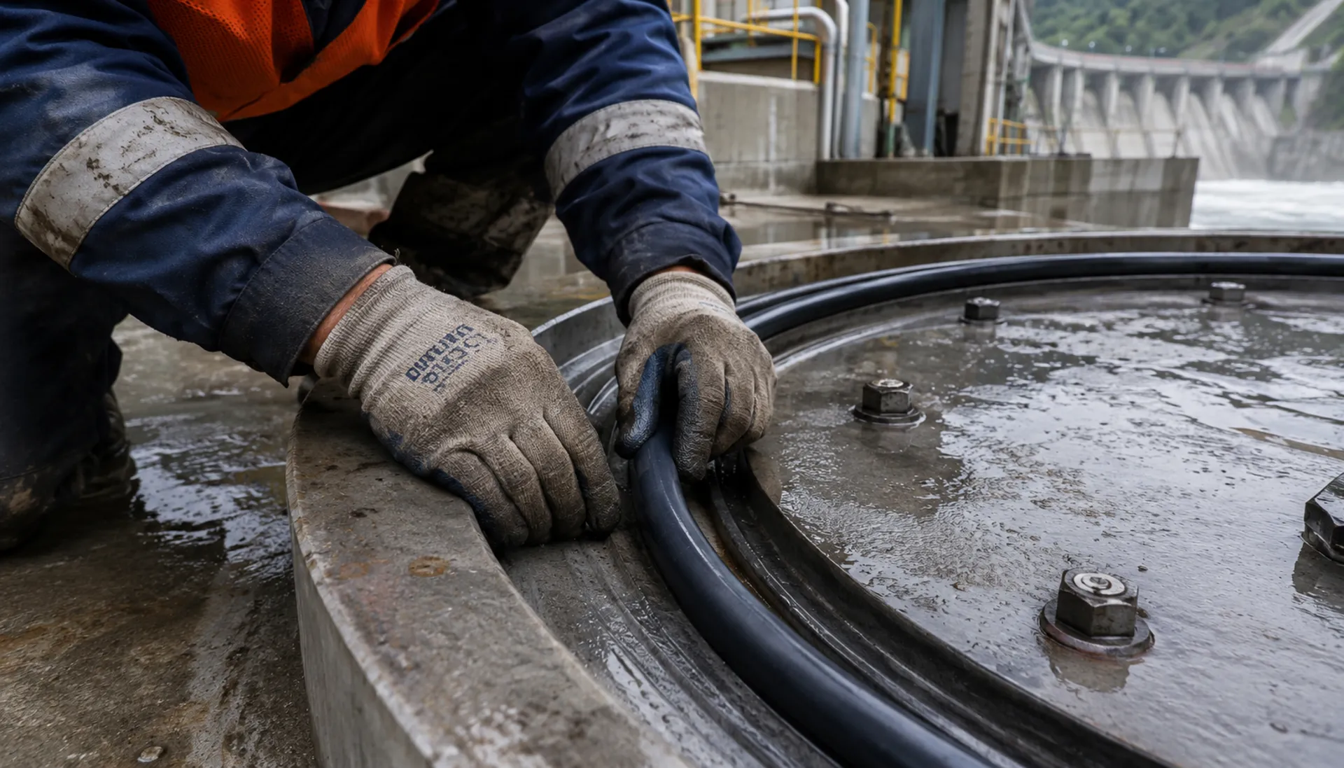
Underwater Bolt Crevice Corrosion: Prevention with 316L Fasteners
Crevice corrosion in thread gaps can reduce bolt cross-section in 5-8 years. 316L stainless steel (PREN≥24) offers improved resistance. This page failure mechanisms and fastener selection criteria for hydropower underwater applications
RISK AUDIT // ENGINEERING DIAGNOSIS
Procurement Pitfall Avoidance Guide
"Common pitfalls when sourcing fasteners for underwater hydropower seals"
QC-AUDIT // REV.5
SCALE 1:1 · 03 ITEMS
RISK-01
Crevice Corrosion of Underwater Bolts Leading to Sudden Fracture
Corrective Measures
RISK-02
Seal Failure of High-Pressure Pipelines
Corrective Measures
RISK-03
Fatigue Fracture of Turbine Runner
Corrective Measures
FIELD-SPECIFIC INSIGHT
Underwater Bolt Crevice Corrosion: Procurement Checkpoints
Crevice corrosion in underwater bolts is often overlooked. The thread gap between bolt and nut creates an oxygen-depleted zone, leading to Cl⁻ concentration and pH drop, causing passive film breakdown. 316L with PREN≥24 reduces this risk compared to 304
WHAT TO CHECK
- 1Specify 316L stainless steel (PREN≥24) for underwater bolts to resist crevice corrosion; avoid 304 (PREN≥18)
- 2Require material certificate confirming PREN value; verify against project corrosion category (C3-C5)
- 3Inspect bolts for pitting depth or corrosion affecting surface area; replace if found
- 4Re-torque fasteners if tension loss exceeds specified torque during periodic inspection
| Check | Why it matters | What to specify |
|---|---|---|
| Material Grade | 304 is susceptible to crevice corrosion in static water; 316L offers higher PREN | 316L stainless steel, PREN≥24, with material certificate |
| Coating/Finish | HDG provides sacrificial protection; thickness must meet ISO 1461 | HDG coating per ISO 1461 |
| Thread Geometry | Thread gaps are crevice sites; coarse threads reduce gap volume | Coarse thread (e. G. , M20) preferred; avoid fine threads |
| Inspection Interval | Crevice corrosion progresses slowly; periodic checks catch early damage | Inspect every 6 months; replace if pitting or corrosion exceeds criteria |
Data based on industry failure analysis; actual corrosion rates depend on water chemistry and temperature. Verify with project-specific corrosion testing
Evidence level: source-page-only
INDUSTRY TECH REFERENCE
Acidic or High-Sulfide Water: Specifying Underwater Bolts & Seals
Water chemistry is the first variable for underwater hardware — settle the water before the grade.
| Water type | Risk to underwater hardware | Specify |
|---|---|---|
| Tropical peat water (pH 4–6) | Corrosion accelerates clearly | 316L or higher; no carbon steel |
| High sulfide / chloride water | High localized-corrosion risk | 316L or higher; skip carbon steel |
INDUSTRY TECH REFERENCE
A Gasket's Trajectory from Tight to Weeping
Example: sealing washers and flange gaskets on pipe flanges.
- 1Gaskets under long-term compression lose their rebound year by year — creep relaxation
- 2When rebound falls short, the gasket absorbs flange preload and a hairline gap opens at the joint
- 3The gap weeps worse under pressure swings, and high-pressure water erodes the sealing face in turn
- 4Response: replace flange gaskets and sealing washers preventively on a 5–8-year cycle — don't wait for a leak
The 5–8-year replacement cycle is a magnitude estimate from research.
INDUSTRY TECH REFERENCE
Underwater Seal Procurement: Verify These Before Ordering
Replacing underwater seals means downtime — settle material and coating in a single order.
- Underground powerhouse air stays at 80–95% RH year-round and metal surfaces keep condensing — bare carbon steel corrodes badly within six months, so specify 304/316L or hot-dip galvanizing + sealing wax for manhole bolts and flange faces
- In the water-level zone (dry-season drawdown, wet-season surge) wet-dry cycling corrodes worse than full immersion — design seal protection for the wet-dry zone
- Write the gasket / O-ring material (EPDM/NBR/PTFE) into the order so nothing gets mixed up on site
SELECTION GUIDE
How to Choose the Right Seal and Fastener
| Operating condition | Recommended option | Key basis |
|---|---|---|
| Confirm project working conditions and technical parameters | Define water type, pressure, temperature, shaft diameter and media | ISO 3601 (O-ring); ASME B16.5 flange rating |
| Select specification grade according to standards | Choose material grade and gasket type per ISO 3506 / ASME B16.20 / ISO 12944-2 | ISO 3506; ASME B16.20 gaskets |
| Determine anti-corrosion and protection scheme | Underwater bolts: 316L (PREN≥24) with anti-seize + thread sealant; HDG per ISO 1461 | 316L PREN≥24 vs 304 PREN≥18; ISO 1461 |
① 316L Mechanical Seal
C3 (ISO 12944-2) with underwater immersion; crevice corrosion risk per ISO 3506
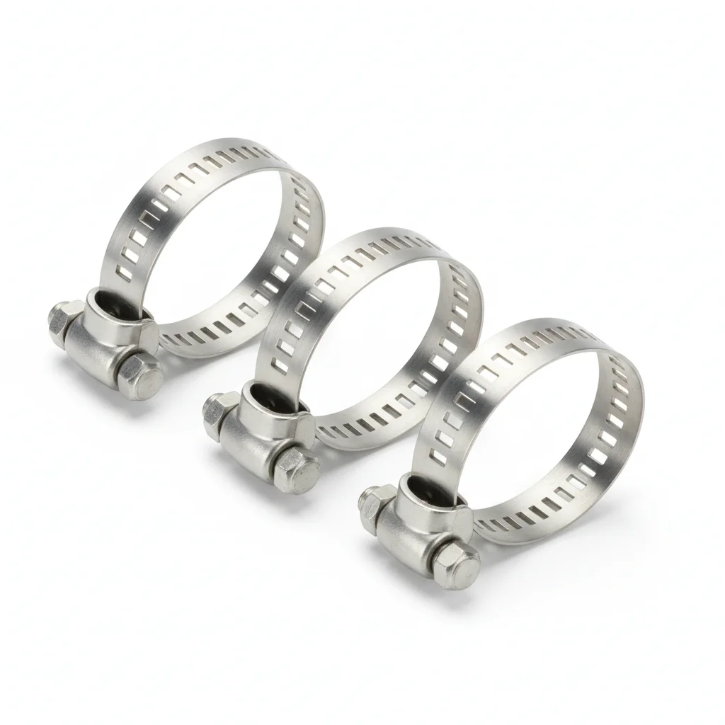
| Manhole Door Bolt | Seal Cord | Clamp | |
|---|---|---|---|
| SPEC | M20-M30 | φ10-30mm | DN50-DN200 |
| MATERIAL | 316L | EPDM Rubber | 316L |
| GRADE | A4-70 | — | — |
| FINISH | HDG >=55um per ISO 1461 | HDG >=55um per ISO 1461 | HDG >=55um per ISO 1461 |
| CORROSION | C3 (ISO 12944-2) | Not applicable (polymer) | C3 (ISO 12944-2) |
| TEMP | -20°C to +80°C | -20°C to +80°C | -20°C to +80°C |
| WEIGHT | ~0.5 kg/piece | ~0.5 kg/piece | ~0.5 kg/piece |
| MOQ | 100 pcs | 100 pcs | 100 pcs |
| PACK | VCI paper + carton | VCI paper + carton | VCI paper + carton |
| STD | ISO 898-1, GB/T 3098.1 | ISO 898-1, GB/T 3098.1 | ISO 898-1, GB/T 3098.1 |
| USE | Underwater Manhole Door | General Sealing | Seal Cord Fixing |
PROCEDURE
- Degrease the manhole door groove and bolt threads with isopropyl alcohol; confirm the EPDM cord (φ10-30mm) is free of cuts and the 316L bolts (M20-M30, A4-70) show no surface pitting.
- Lay the seal cord continuously in the groove without stretching; use 316L clamps (DN50-DN200) at intervals to hold the cord in place and prevent displacement during closure.
- Insert the 316L bolts with anti-seize compound on threads; tighten in a star pattern to the torque specified for A4-70 grade, ensuring the manhole door compresses the cord evenly.
- Verify the door sits flush (no gaps >0.1mm); check that the EPDM cord is not extruded beyond the flange face.
- Apply torque seal paint to the bolt heads and nuts; record the torque values and the batch numbers of the bolts and cord in the QA log for traceability.
COMMON ERRORS
| ✕ WRONG | CONSEQUENCE | ✓ CORRECT |
|---|---|---|
| Using 304 stainless steel bolts (PREN≥18) instead of 316L (PREN≥24) for the manhole door. | Crevice corrosion in the thread gap can reduce the bolt cross-section by up to 30% within 5-8 years, risking sudden fracture. | Specify 316L stainless steel bolts with PREN≥24 and verify the material certificate before installation. |
| Skipping the anti-seize compound on bolt threads before tightening. | Thread galling can occur, and gaps remain filled with stagnant water, accelerating crevice corrosion. | Apply a suitable anti-seize compound to all threads and under the bolt head to fill crevices and prevent seizing. |
| Over-tightening the bolts, causing the EPDM cord to be crushed beyond its elastic limit. | The seal loses its resilience, leading to leakage under water pressure. | Follow the specified torque for the bolt size and grade; use a calibrated torque wrench to ensure consistent compression. |
MAINTENANCE
Inspect the manhole seal and bolts seasonally or during each overhaul window. Check for any signs of leakage or corrosion on the bolt heads and around the flange. Re-torque bolts that have lost tension beyond acceptable limits. Replace any bolt showing pitting depth greater than 0.3mm or corrosion affecting more than 5% of the surface area. For long-term reliability, plan a full disassembly and inspection of a representative sample every few years, replacing critical fasteners as needed.
② Manhole Door Gasket
C4 Harsh per ISO 12944-2
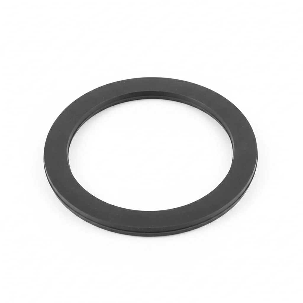
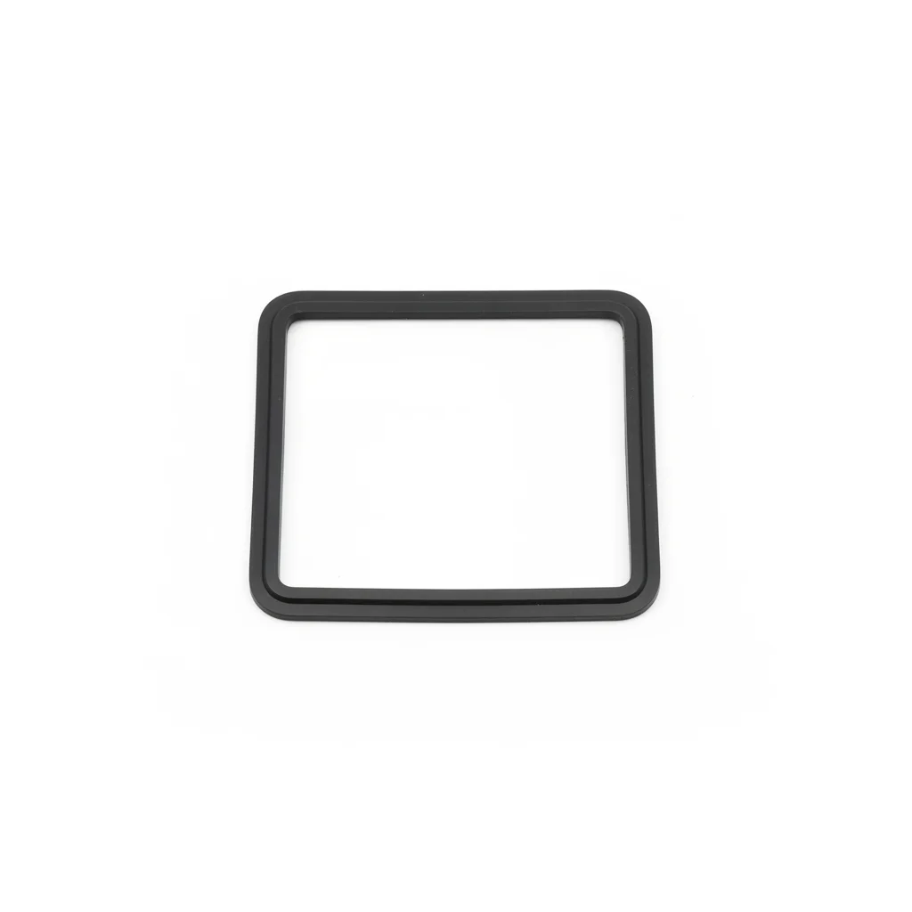
| Gasket | Gasket | Gasket | |
|---|---|---|---|
| SPEC | Φ500×10mm | Φ500×10mm | Φ500×10mm |
| MATERIAL | EPDM Rubber | EPDM Rubber | EPDM Rubber |
| GRADE | — | — | — |
| FINISH | HDG >=55um per ISO 1461 | HDG >=55um per ISO 1461 | HDG >=55um per ISO 1461 |
| CORROSION | Not applicable (polymer) | Not applicable (polymer) | Not applicable (polymer) |
| TEMP | -20°C to +80°C | -20°C to +80°C | -20°C to +80°C |
| WEIGHT | ~0.5 kg/piece | ~0.5 kg/piece | ~0.5 kg/piece |
| MOQ | 100 pcs | 100 pcs | 100 pcs |
| PACK | VCI paper + carton | VCI paper + carton | VCI paper + carton |
| STD | ISO 898-1, GB/T 3098.1 | ISO 898-1, GB/T 3098.1 | ISO 898-1, GB/T 3098.1 |
| USE | Fresh Water Environment Manhole Door | Oily Media Sealing | High Temperature/Chemical Media Sealing |
PROCEDURE
- Clean the manhole door and valve flange faces with a solvent to remove oil and debris, ensuring surface roughness Ra <3.2 μm for proper gasket seating.
- Position the EPDM gasket (Φ500×10mm) centered on the flange, verifying it is free from twists or cuts before bolting.
- Use 316L bolts (A4-70, M20–M30) with PTFE-coated washers; tighten in a star pattern to achieve uniform compression, following ASME B16.20 gasket seating guidelines.
- After initial tightening, perform a second pass to compensate for gasket relaxation, then mark the bolt heads to indicate final torque.
- Conduct a visual inspection of the gasket edge for extrusion and verify no water seepage during the initial pressurization test.
COMMON ERRORS
| ✕ WRONG | CONSEQUENCE | ✓ CORRECT |
|---|---|---|
| Reusing a compressed or damaged EPDM gasket on the manhole door | A gasket that has lost its resilience cannot maintain a seal under the fluctuating pressures of a hydropower penstock, leading to leaks that may wash out the joint and accelerate crevice corrosion on the bolts. | Always install a new EPDM gasket of the specified Φ500×10mm size, checking for Shore A hardness in the 40–70 range and ensuring no surface defects before assembly. |
| Tightening the 316L bolts in a circular sequence instead of a cross-pattern | Uneven compression distorts the gasket, creating a low-stress path for water ingress that promotes crevice corrosion in the thread gaps and can lead to sudden joint failure. | Tighten the bolts in a star or cross-pattern sequence, performing multiple passes at increasing torque to ensure uniform gasket compression across the flange. |
MAINTENANCE
During each dry-season overhaul, inspect the manhole gasket for hardening, cracking, or compression set; replace if the Shore A hardness exceeds 70 or if any surface degradation is visible. Check bolt torque on a representative sample and re-tighten any that have lost more than 15% of the specified preload, as per the page's maximum allowable tension loss criterion.
REFERENCED STANDARDS
Technical Basis and Reference Standards
SUPPLIER CAPABILITY
Quality, Delivery & Customization
Quality Control
- ✓MTC material certificates with every batch
- ✓Key parts sampled for hardness/salt spray/torque coefficient
- ✓100% inspection or AQL sampling before shipment
Delivery
- ✓Standard parts made to order: 7-15 days
- ✓Custom parts: 25-45 days
- ✓FOB/CIF/DDP supported
Customization
- ✓Drawing review and material matching
- ✓Non-standard sizes/heads/threads
- ✓Small-batch prototyping supported
Certification
- ✓Material certificates (MTC)
- ✓Spectrographic analysis reports
- ✓Salt spray test reports (on request)
MOQ: No MOQ for standard parts; custom parts assessed by process complexity
FAQ
Frequently Asked Questions
RELATED READING
Keep Reading & Next Step
BEYOND TECHNICAL SPECS
Finding the right factory, controlling quality, delivering on time — that's the real challenge. We cover fasteners, rubber, plastics, industrial textiles. One team, end to end.
SEE CAPABILITIES →