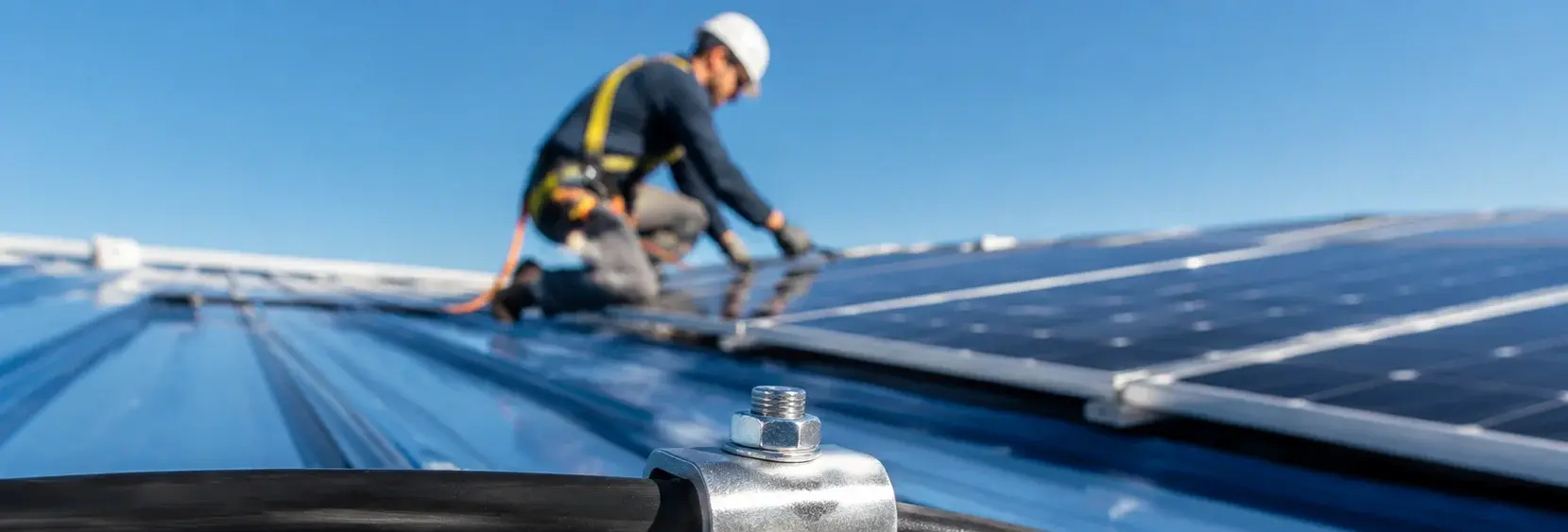
Rooftop Solar Cable Clips: Compare Materials and Fixing Methods
Unfixed cables rub against rail edges under wind vibration, wearing through insulation in 3 years and causing DC arc flash. Choosing the right clip material and fixing method is critical. Compare nylon (UV-stabilized PA66), stainless steel (304 with EPDM liner), and magnetic mounts for holding force, lifespan, and installation constraints
RISK AUDIT // ENGINEERING DIAGNOSIS
Purchasing Pitfall Guide
"On the rooftop, cable clip failures are not a matter of if, but when—here's what to watch for."
QC-AUDIT // REV.5
SCALE 1:1 · 03 ITEMS
RISK-01
Unfixed Cables Cause Insulation Wear from Wind
Corrective Measures
RISK-02
Plastic Cable Clips Become Brittle and Break Under UV Exposure
Corrective Measures
RISK-03
Improper Cable Clip Selection Causes 'Secondary Wear'
Corrective Measures
FIELD-SPECIFIC INSIGHT
3 Material Options: What to Check Before You Specify
Each clip material solves a different failure mode: nylon is for inland C3 environments but UV degrades it; stainless steel resists corrosion in coastal C4-C5 areas but requires EPDM liner to avoid secondary wear; magnetic mounts avoid drilling but have limited lifespan and holding force. The table below highlights the key checks for procurement
WHAT TO CHECK
- 1Inspect for brittleness after 5 years
- 2Stainless steel 304 with EPDM liner: prevents metal-to-cable abrasion; specify A2-70 grade for coastal areas
- 3Magnetic mount: holding force ≥5kg, but rubber housing ages in 5-8 years; not for permanent installations
| Check | Why it matters | What to specify |
|---|---|---|
| UV resistance | Nylon becomes brittle under UV, causing clip failure and cable release | Require UL 746C f1 rating or UV-stabilized PA66 for outdoor use |
| Corrosion resistance | Coastal salt spray corrodes standard clips, leading to rust and failure | For C4-C5 environment, specify 304 stainless steel (A2-70) or equivalent |
| Cable abrasion protection | Metal clips without liner can cut cable insulation under vibration | Stainless steel clips must include EPDM or rubber liner to prevent secondary wear |
| Holding force and fixing method | Magnetic mounts may detach in high wind; adhesive bases may lose grip on dusty surfaces | For magnetic: holding force ≥5kg; for adhesive: use 3M VHB tape and clean surface before application |
Lifespan estimates (8-12, 20-25, 5-8 years) are based on typical conditions; actual life depends on site-specific UV, temperature, and wind loads. Always verify with supplier test data
Evidence level: source-page-only
INDUSTRY TECH REFERENCE
From a Loose Cable Clip to a Roof Fire: The DC Arc Path
Example: DC cables laid along the rail without secure fixing. The clip is the first physical defense on the DC side — this chain shows why it must never loosen.
- 1A clip loosens or is skipped, the cable loses its restraint, and it sags and swings in wind vibration
- 2The sagging cable rubs the roof surface or rail edges, and the insulation gradually wears through
- 3Once the insulation is worn, the bare conductor touches a metal part and a fault path forms in the DC circuit
- 4A 400–1500 V DC arc has no zero crossing, does not self-extinguish, and keeps burning at thousands of degrees
- 5The arc ignites roofing and nearby combustibles — one loose clip escalates into a roof fire
This chain carries no standalone magnitude figures; the 400–1500 V range, the no-zero-crossing behavior, and thousands-of-degrees arc temperature follow the KB's verified basis (KB §6: DC arc has no zero crossing — electrical common knowledge).
INDUSTRY TECH REFERENCE
Five Specs for Cable Clips: Material, Spacing, Double Protection
Scope: clips for rooftop DC cables. Align these five points before ordering — don't let a single clip sink the whole plant.
- Use UV-stabilized PA66 (carbon black ≥2%) — ordinary nylon clips embrittle within 2–3 years under rooftop UV
- Use 304 stainless clips at critical points: cable entries through vents/flue penetrations, long-exposure or wear-prone runs
- Fixing spacing ≤500 mm (suggested) — wider spacing lets the cable swing and rub under wind vibration
- Provide double-layer protection where cables pass through vents or flue openings
- Fits cable diameters φ4–8 mm, roughly a few hundred clips per MW
Spacing ≤500 mm is a suggested value; carbon black ≥2%, 2–3 year UV embrittlement, φ4–8 mm, and hundreds per MW follow the KB; 304 at critical points follows the KB recommendation.
INDUSTRY TECH REFERENCE
Why a DC Arc Cannot Be Put Out
Before picking a clip, understand what it is defending against.
PV DC strings run at 400–1500 V. An AC arc crosses zero every cycle, which is how it can be extinguished; a DC arc has no zero crossing — once established it does not die out on its own and can burn at thousands of degrees. So on the DC side, “cut the power and it goes out” is not a strategy; protection has to be preventive: cables fixed in place, insulation intact, no bare conductor touching metal. Clip spacing and material are, in effect, the first physical line of DC arc-fire defense.
PLAN COMPARISON
Three-Plan Core Parameter Comparison
Compare row by row. Click column headers to jump to plan details.
| A · Plan A · Standard Nylon Cable Clip Configuration | B · Plan B · Stainless Steel Cable Clip Enhanced Configuration | C · Plan C · Magnetic Solution (No Drilling Required) | |
|---|---|---|---|
| 1. NYLON CABLE CLIP (UV STABILIZED) | |||
| SPEC | For 4-10mm² Cables | For 4-10mm² Cables | Holding Force ≥ 5kg |
| MATERIAL | Nylon PA66 + UV Stabilizer | 304 Stainless Steel + EPDM Liner | Neodymium Magnet + Rubber Housing |
| GRADE | UL 746C f1 Black | A2-70 | IP65 Black |
| FINISH | HDG >=55um per ISO 1461 | HDG >=55um per ISO 1461 | HDG >=55um per ISO 1461 |
| 2. SELF-ADHESIVE CABLE CLIP BASE | |||
| SPEC | Fits Cable Clip Bottom | M4×12mm | For 4-10mm² |
| MATERIAL | 3M VHB Double-Sided Tape + Nylon | 304 Stainless Steel | Magnet + PA66 |
| GRADE | Weather-Resistant | A2-70 | UV Stabilized |
| FINISH | HDG >=55um per ISO 1461 | HDG >=55um per ISO 1461 | HDG >=55um per ISO 1461 |
SELECTION GUIDE
Still Unsure About the Right Clip?
| Operating condition | Recommended option | Key basis |
|---|---|---|
| Standard roof (inland, C3 environment) | Plan A · Nylon cable clips (UV-stabilized PA66, UL 746C f1 black) | UL 746C f1; ISO 12944-2 C3 |
| Coastal / high wind / 25-year life (C4-C5) | Plan B · Stainless steel 304 clips (A2-70) + EPDM liner | ISO 12944-2 C4-C5; UL 62275 |
| Color steel tile roof / no drilling / temporary setup | Plan C · Magnetic mounts (holding force ≥5kg), for temporary use only | Magnetic holding force ≥5kg; ISO 12944-2 C5-M |
Plan A · Standard Nylon Cable Clip Configuration
C3 (ISO 12944-2)
| Nylon Cable Clip (UV Stabilized) | Self-Adhesive Cable Clip Base | |
|---|---|---|
| SPEC | For 4-10mm² Cables | Fits Cable Clip Bottom |
| MATERIAL | Nylon PA66 + UV Stabilizer | 3M VHB Double-Sided Tape + Nylon |
| GRADE | UL 746C f1 Black | Weather-Resistant |
| FINISH | HDG >=55um per ISO 1461 | HDG >=55um per ISO 1461 |
| CORROSION | C3 (ISO 12944-2) | C3 (ISO 12944-2) |
| TEMP | -20°C to +80°C | -20°C to +80°C |
| WEIGHT | ~0.5 kg/piece | ~0.5 kg/piece |
| MOQ | 100 pcs | 100 pcs |
| PACK | VCI paper + carton | VCI paper + carton |
| STD | ISO 898-1, GB/T 3098.1 | ISO 898-1, GB/T 3098.1 |
| USE | Cable fixing on rail, spacing 0.5-1m | Temporary fixing on color steel tile surface (auxiliary use) |
PROCEDURE
- Clean the rail surface with isopropyl alcohol, removing any grease or dust that could compromise the UV-stabilized PA66 clip's grip.
- Position the nylon cable clip (UL 746C f1 black) over the DC cable, ensuring the cable sits freely in the rounded chamfer (R ≥ 0.5mm) with 0.5-1mm clearance.
- Snap the clip closed and verify the cable is not pinched or deformed, then secure the clip to the rail using the self-tapping screw provided.
- Space clips at 0.5-1m intervals along the rail, keeping positive and negative cables separated by at least 100mm.
- For temporary positioning on color steel tiles, apply the self-adhesive base (3M VHB) to a clean, dry surface and press firmly for 10 seconds.
COMMON ERRORS
| ✕ WRONG | CONSEQUENCE | ✓ CORRECT |
|---|---|---|
| Selecting a non-UV-stabilized nylon clip | The clip becomes brittle and cracks within 2 years, releasing the cable and leading to insulation wear from wind vibration. | Specify nylon PA66 with UV stabilizer and UL 746C f1 rating; black color preferred for inherent UV protection. |
| Using a clip with sharp edges or an undersized opening | The clip cuts into the cable insulation under vibration, causing secondary wear and potential DC arc flash. | Ensure clip opening has rounded chamfer (R ≥ 0.5mm) and inner diameter matches cable OD with 0.5-1mm clearance. |
MAINTENANCE
Inspect clips seasonally for cracking or brittleness, especially after 5 years of UV exposure. Re-tighten any loose clips to the specified torque and replace any clip showing signs of UV degradation or cable wear.
Plan B · Stainless Steel Cable Clip Enhanced Configuration
C4-C5 coastal / high wind per ISO 12944-2
| Cable Clip | Self-Tapping Screw | |
|---|---|---|
| SPEC | For 4-10mm² Cables | M4×12mm |
| MATERIAL | 304 Stainless Steel + EPDM Liner | 304 Stainless Steel |
| GRADE | A2-70 | A2-70 |
| FINISH | HDG >=55um per ISO 1461 | HDG >=55um per ISO 1461 |
| CORROSION | C3 (ISO 12944-2) | C3 (ISO 12944-2) |
| TEMP | -20°C to +80°C | -20°C to +80°C |
| WEIGHT | ~0.5 kg/piece | ~0.5 kg/piece |
| MOQ | 100 pcs | 100 pcs |
| PACK | VCI paper + carton | VCI paper + carton |
| STD | ISO 898-1, GB/T 3098.1 | ISO 898-1, GB/T 3098.1 |
| USE | Cable fixing in coastal/high wind areas | Fixing cable clip to rail |
PROCEDURE
- Wipe the rail surface clean of salt residue and dust with a dry cloth; ensure the mounting area is dry.
- Position the 304 stainless steel clip (A2-70) over the 4-10mm² cable, ensuring the EPDM liner fully wraps the cable jacket.
- Align the clip base with the pre-drilled rail hole and drive the M4×12mm self-tapping screw with a power drill set to low torque to avoid over-tightening.
- Verify the clip holds the cable snugly with 0.5-1mm clearance between the cable and the clip opening; the cable should not slide when gently pulled.
- Space clips every 0.5-1m along the rail; for cable bends, place one clip on each side of the bend.
- After installation, inspect each clip for any metal-to-cable contact; adjust the EPDM liner if exposed.
COMMON ERRORS
| ✕ WRONG | CONSEQUENCE | ✓ CORRECT |
|---|---|---|
| Using a standard nylon clip in a coastal C4-C5 area without UV stabilization | The clip becomes brittle under UV and salt-laden air, cracking within 2 years and releasing the cable to rub against the rail. | Select the 304 stainless steel clip with EPDM liner rated for coastal environments; verify A2-70 grade on the screw. |
| Overtightening the self-tapping screw so the clip compresses the cable insulation | The cable is flattened at the clip opening, and the metal edge can cut through the XLPE sheath under vibration, leading to DC arc flash. | Drive the screw just until the clip is snug; leave 0.5-1mm clearance between the cable and the clip opening as per the spec. |
MAINTENANCE
Inspect clips semi-annually for signs of rust or EPDM wear; in high wind areas, verify all screws remain tight after storm seasons. Replace any clip with cracked or brittle EPDM liner to prevent metal-on-cable contact.
Plan C · Magnetic Solution (No Drilling Required)
C5-M extreme (salt, humidity, industrial) per ISO 12944-2
| Magnetic Cable Mount | Magnetic Cable Guide Clip | |
|---|---|---|
| SPEC | Holding Force ≥ 5kg | For 4-10mm² |
| MATERIAL | Neodymium Magnet + Rubber Housing | Magnet + PA66 |
| GRADE | IP65 Black | UV Stabilized |
| FINISH | HDG >=55um per ISO 1461 | HDG >=55um per ISO 1461 |
| CORROSION | C3 (ISO 12944-2) | C3 (ISO 12944-2) |
| TEMP | -20°C to +80°C | -20°C to +80°C |
| WEIGHT | ~0.5 kg/piece | ~0.5 kg/piece |
| MOQ | 100 pcs | 100 pcs |
| PACK | VCI paper + carton | VCI paper + carton |
| STD | ISO 898-1, GB/T 3098.1 | ISO 898-1, GB/T 3098.1 |
| USE | Magnetic fixing of cables on color steel tile surface | Magnetic cable routing guide clip |
PROCEDURE
- Clean the color steel tile surface with a dry cloth to remove dust and oil; ensure the surface is dry.
- Select a magnetic mount with holding force ≥5kg and position it on the steel tile where the cable will run.
- Press the mount firmly for 3-5 seconds to ensure full magnetic contact, then route the 4-10mm² cable through the clip guide.
- For long cable runs, space magnetic mounts every 0.5-1m; avoid placing them on seams or raised ribs where the magnet may not seat flat.
- After installation, tug each cable gently to verify the magnet holds; if any mount slides, reposition to a flatter area of the tile.
- For temporary setups, mark each mount with a date sticker to track aging; plan for removal within the 5-8 year lifespan.
COMMON ERRORS
| ✕ WRONG | CONSEQUENCE | ✓ CORRECT |
|---|---|---|
| Installing magnetic mounts on rusty or painted color steel tiles without checking surface condition | The magnetic force is reduced by the gap and surface rust, causing the mount to detach in high wind, releasing the cable. | Choose clean, unpainted, or lightly painted steel tiles; if rust is present, use a mechanical clip instead of relying on the magnet. |
| Using magnetic mounts as the sole fixing method in typhoon-prone coastal areas | After 3 years, the rubber housing ages and holding force drops to 60% of the ≥5kg rating, so the mount can blow off during a typhoon. | Combine magnetic mounts with mechanical clips on critical spans, or use only for short-term installations where you can monitor them regularly. |
MAINTENANCE
Check magnetic mounts for rubber cracking or loss of holding force seasonally, especially before typhoon season. Verify the holding force is still ≥5kg by gently pulling the cable; if the mount slides, replace it. For temporary setups, remove or replace mounts after 5-8 years of outdoor exposure.
REFERENCED STANDARDS
Referenced Standards & Authorities
SUPPLIER CAPABILITY
Quality, Delivery & Customization
Quality Control
- ✓MTC material certificates with every batch
- ✓Key parts sampled for hardness/salt spray/torque coefficient
- ✓100% inspection or AQL sampling before shipment
Delivery
- ✓Standard parts made to order: 7-15 days
- ✓Custom parts: 25-45 days
- ✓FOB/CIF/DDP supported
Customization
- ✓Drawing review and material matching
- ✓Non-standard sizes/heads/threads
- ✓Small-batch prototyping supported
Certification
- ✓Material certificates (MTC)
- ✓Spectrographic analysis reports
- ✓Salt spray test reports (on request)
MOQ: No MOQ for standard parts; custom parts assessed by process complexity
FAQ
FAQ
RELATED READING
Keep Reading & Next Step
BEYOND TECHNICAL SPECS
Finding the right factory, controlling quality, delivering on time — that's the real challenge. We cover fasteners, rubber, plastics, industrial textiles. One team, end to end.
SEE CAPABILITIES →