
PV Cable Connector and Gland Hardware: Stop Water Ingress
Solar-farm cable failures are often blamed on the cable, but the leak or abrasion point can be the connector, gland, cord grip or support clip. The procurement line should cover both the PV cable and the hardware that protects it
RISK AUDIT // ENGINEERING DIAGNOSIS
Procurement Pitfall Guide
"On a solar farm, the cable gets the blame, but the leak often starts at the gland, the connector, or a chafing cable tie."
QC-AUDIT // REV.5
SCALE 1:1 · 03 ITEMS
RISK-01
Incorrect Wire Diameter Selection Leads to Excessive Line Loss
Corrective Measures
RISK-02
Jacket Aging and Cracking Leads to Ground Faults
Corrective Measures
RISK-03
Cable Gland Water Ingress Causes String Ground Alarm
Corrective Measures
FIELD-SPECIFIC INSIGHT
Cable Failure Often Starts at the Hardware Interface
IEC 62930 gives the PV DC cable scope, while Eaton's public PV cord-grip sample shows that glands and cord grips are part of the sealing and support package. The page should therefore check cable, connector and gland together
WHAT TO CHECK
- 1Check whether the cable is specified for the PV DC side before selecting connectors and glands
- 2Treat gland sealing and strain relief as separate requirements; a sealed hole can still leave cable movement unmanaged
- 3Specify cable clips or supports where wind, thermal movement or maintenance traffic can cause abrasion
- 4Do not mix connector families unless the supplier confirms compatibility and test evidence
| Check | Why it matters | What to specify |
|---|---|---|
| Cable scope | A cable may be electrically suitable in one use but not documented for PV DC service | PV cable standard reference, conductor type and supplier test document |
| Gland or cord grip | Water ingress and strain can enter at the enclosure or combiner-box interface | Gland type, seal material, cord grip layout and enclosure interface |
| Support hardware | Loose cable runs can abrade against frames, rails or tray edges | Clip, tie or support spacing method and material compatibility with the cable jacket |
IEC 62930 is used for PV cable scope; Eaton is only a supplier sample for cord-grip hardware. Project ratings and compatibility must come from supplier documents
Evidence level: standard-backed
INDUSTRY TECH REFERENCE
DC Cable Fixing Hardware Compared: Material, Diameter and Spacing
Cable clips are not filler consumables — material, matched diameter and layout spacing decide whether they survive outdoors. The comparison:
| Parameter | Cable fixing clip (304/PA66) | Critical-location practice |
|---|---|---|
| Material | 304 stainless or PA66 nylon | Stainless clips at critical locations (recommended) |
| Matched cable diameter | φ4-8 mm | Match to the actual outer diameter of the cable |
| Volume per project | Thousands per MW (magnitude estimate) | Stock the full array against this volume |
| Spacing | ≤500 mm (recommended) | Recheck section by section during inspection |
"Thousands per MW" is a magnitude estimate; φ4-8 mm and ≤500 mm spacing come from the typical-scenario table; stainless clips at critical locations are recommended.
INDUSTRY TECH REFERENCE
A Loose Base Bolt: How Cable Tugging Ends in a DC Arc
Under-torque the expansion bolts under the inverter and the first casualty is not the base — it is the string connectors. The chain:
- 1Base expansion bolts under-torqued (M12 calls for 50-60 N·m) shake loose over time
- 2The inverter creeps under vibration, yanking the cables back and forth
- 3Strain travels up the run until the plug-in contacts part slightly and resistance rises
- 4Current keeps the degraded joint hot and the contact faces corrode further
- 5Insulation breaks down and the string flashes over — a DC arc that never goes out
50-60 N·m is the stainless expansion-bolt product rating; the chain runs under-torque → vibration shift → cable tugging → joint loosening → arc, and a DC arc has no zero crossing so it does not self-extinguish.
INDUSTRY TECH REFERENCE
Semiannual Checks for DC Cables and Connectors
Inspections track two things only: fixings holding and joints staying cool. The cadence and criteria:
- Inspect twice a year: run IR over the full DC cable run to find local hot spots
- Re-check clip spacing at ≤500 mm and refill any loose or missing clip; use stainless clips at critical locations (recommended)
- After any MC4 disassembly, re-verify the lock — listen for the click and pull to confirm it holds
Twice-yearly inspection is the KB-recommended cadence; ≤500 mm spacing and stainless clips at critical locations are recommended values.
PLAN COMPARISON
Three-Plan Core Parameter Comparison
Compare row by row. Click column headers to jump to plan details.
| A · Plan A · Standard DC Side Configuration | B · Plan B · Long Distance Low Loss Configuration | C · Plan C · Extreme Environment / Stringent Safety Regulation Configuration | |
|---|---|---|---|
| 1. PV1-F SINGLE CORE DC CABLE | |||
| SPEC | 4mm² Black/Red | 6mm²/10mm² Black/Red | 10/16/25mm² |
| MATERIAL | Tinned Copper (IEC 60228 Class 5 Flexible Conductor) + XLPE Cross-linked Polyethylene Jacket | Tinned Copper Class 5 + XLPE + Reinforced Nylon Braided Layer | Aluminum Alloy Conductor (8030 grade) + XLPE + Double Jacket |
| GRADE | DC 1.5kV (AC 1.0kV) | DC 1.5kV | DC 2kV, 50% lighter than copper |
| FINISH | HDG >=55um per ISO 1461 | HDG >=55um per ISO 1461 | HDG >=55um per ISO 1461 |
| 2. PV1-F DOUBLE CORE DC CABLE | |||
| SPEC | 2×4mm² Black/Red | 2×6mm² | 4/6/10mm² |
| MATERIAL | Tinned Copper + XLPE + PVC Outer Sheath | Tinned Copper + XLPE + LSZH Low Smoke Zero Halogen Outer Sheath | Additional nickel plating layer over tinning + XLPE |
| GRADE | DC 1.5kV | DC 1.5kV, compliant with IEC 60332-1 Flame Retardant | Salt spray resistance 2000h (IEC 60068) |
| FINISH | HDG >=55um per ISO 1461 | HDG >=55um per ISO 1461 | HDG >=55um per ISO 1461 |
| 3. PV WEATHER-RESISTANT CABLE TIE | |||
| SPEC | 3.6×200mm Black | 4.6×300mm | 4.6×300mm |
| MATERIAL | Nylon 66 (PA66) + Carbon Black (≥2%) Anti-UV | 304 Stainless Steel (Epoxy Coated Surface) | 316 Stainless Steel (Uncoated) |
| GRADE | Temperature -40°C to 85°C | Temperature -60°C to 150°C | Seawater corrosion resistance 5000h salt spray |
| FINISH | HDG >=55um per ISO 1461 | HDG >=55um per ISO 1461 | HDG >=55um per ISO 1461 |
| 4. NYLON CABLE GLAND | |||
| SPEC | PG9/PG11/PG13.5 | PG11/PG16/PG21 | PG11-PG21 |
| MATERIAL | Nylon PA66 + EPDM Sealing Ring | Brass Nickel Plated + Chloroprene Rubber Seal | 316 Stainless Steel + FFKM Perfluoroelastomer Seal |
| GRADE | IP68 (2m/72h) | IP68/IP69K, Rodent Resistant | IP69K, Acid and Alkali Corrosion Resistant |
| FINISH | HDG >=55um per ISO 1461 | HDG >=55um per ISO 1461 | HDG >=55um per ISO 1461 |
| 5. MC4 CRIMPING TOOL KIT | |||
| SPEC | 2.5/4/6mm² | PA Corrugated Tube φ20-32mm | FRP Fiberglass 100×50mm |
| MATERIAL | Chrome Vanadium Steel Pliers + Positioning Die | Nylon PA6 + Anti-UV | Fiber Reinforced Plastic (FRP) |
| GRADE | — | IP67 | Flame Retardant V0, Salt Spray Resistant 3000h |
| FINISH | HDG >=55um per ISO 1461 | HDG >=55um per ISO 1461 | HDG >=55um per ISO 1461 |
Plan A · Standard DC Side Configuration
C3 inland, standard string spacing, laying distance ≤80m
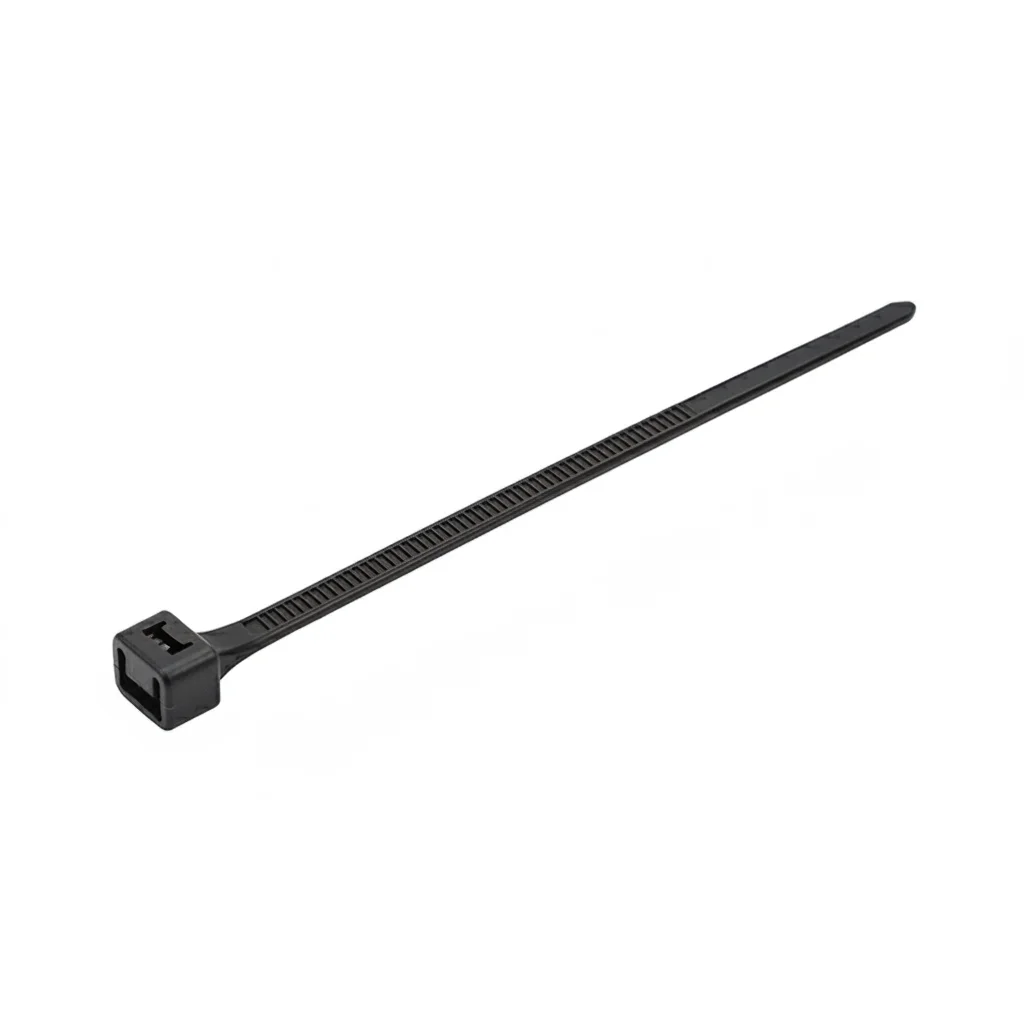
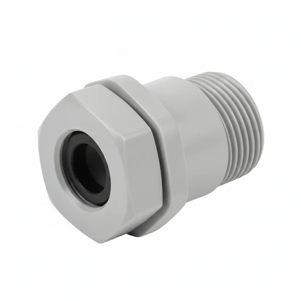
| PV1-F Single Core DC Cable | PV1-F Double Core DC Cable | PV Weather-resistant Cable Tie | Nylon Cable Gland | MC4 Crimping Tool Kit | |
|---|---|---|---|---|---|
| SPEC | 4mm² Black/Red | 2×4mm² Black/Red | 3.6×200mm Black | PG9/PG11/PG13.5 | 2.5/4/6mm² |
| MATERIAL | Tinned Copper (IEC 60228 Class 5 Flexible Conductor) + XLPE Cross-linked Polyethylene Jacket | Tinned Copper + XLPE + PVC Outer Sheath | Nylon 66 (PA66) + Carbon Black (≥2%) Anti-UV | Nylon PA66 + EPDM Sealing Ring | Chrome Vanadium Steel Pliers + Positioning Die |
| GRADE | DC 1.5kV (AC 1.0kV) | DC 1.5kV | Temperature -40°C to 85°C | IP68 (2m/72h) | — |
| FINISH | HDG >=55um per ISO 1461 | HDG >=55um per ISO 1461 | HDG >=55um per ISO 1461 | HDG >=55um per ISO 1461 | HDG >=55um per ISO 1461 |
| CORROSION | C3 (ISO 12944-2) | C3 (ISO 12944-2) | C3 (ISO 12944-2) | C3 (ISO 12944-2) | C3 (ISO 12944-2) |
| TEMP | -20°C to +80°C | -20°C to +80°C | -20°C to +80°C | -20°C to +80°C | -20°C to +80°C |
| WEIGHT | ~0.5 kg/piece | ~0.5 kg/piece | ~0.5 kg/piece | ~0.5 kg/piece | ~0.5 kg/piece |
| MOQ | 100 pcs | 100 pcs | 100 pcs | 100 pcs | 100 pcs |
| PACK | VCI paper + carton | VCI paper + carton | VCI paper + carton | VCI paper + carton | VCI paper + carton |
| STD | ISO 898-1, GB/T 3098.1 | ISO 898-1, GB/T 3098.1 | ISO 898-1, GB/T 3098.1 | ISO 898-1, GB/T 3098.1 | ISO 898-1, GB/T 3098.1 |
| USE | Module to string combiner, string to combiner box | String to combiner box (reduces installation work of two single cores) | Cable fixing along support rails, spacing ≤0.5m | Sealing cable entry holes of combiner box/inverter | On-site crimping of MC4 terminals, ensuring contact resistance <0.5mΩ |
PROCEDURE
- Confirm the PV1-F cable size against string current and run length before pulling, keeping 4mm² for <10A and ≤80m per the page guidance.
- Lay the 4mm² single-core or 2×4mm² double-core cable along the support rail, fixing with the PA66 weather-resistant cable tie at ≤0.5m spacing.
- Terminate the DC cable into the combiner box or inverter using the nylon cable gland (PG9/PG11/PG13.5), ensuring the EPDM sealing ring seats fully around the jacket.
- Crimp MC4 connectors with the 2.5/4/6mm² tool kit so the contact resistance stays below 0.5mΩ as specified for the crimp.
- Form a drip loop (U-bend) on each cable before the MC4 connection to keep water from creeping into the connector.
- Inspect every gland and connector visually for seal gaps and jacket damage before energizing the string.
COMMON ERRORS
| ✕ WRONG | CONSEQUENCE | ✓ CORRECT |
|---|---|---|
| Overtightening the nylon gland until the EPDM ring distorts or the PA66 threads strip. | The seal loses IP68 (2m/72h) integrity, rainwater tracks along the cable into the combiner box, and the string trips on ground-fault alarm during wet weather. | Tighten the gland only until the sealing ring just grips the jacket, then check that the cable cannot be pulled through by hand. |
| Bypassing the drip loop and running the cable straight into the MC4 connector. | Water films along the jacket and enters the connector, causing corrosion and intermittent string faults. | Leave a U-bend in the cable at each connector entry so water drips off before reaching the terminal. |
| Using a standard cable tie in place of the PV weather-resistant PA66 tie with ≥2% carbon black. | The tie degrades under UV within a few seasons, the cable is no longer supported, and it rubs against the rail causing jacket abrasion. | Use the specified PA66 anti-UV cable tie and install it at ≤0.5m intervals along the support rail. |
MAINTENANCE
At each seasonal inspection, check that cable ties remain tight and un-cracked, that nylon glands still show no water ingress, and that MC4 connections are free of corrosion; re-torque or replace any component showing UV embrittlement or seal compression loss.
Plan B · Long Distance Low Loss Configuration
C4 Harsh per ISO 12944-2
| PV1-F Single Core DC Cable (Reinforced) | PV1-F Double Core DC Cable (Reinforced) | Weather-resistant Stainless Steel Cable Tie | Metal Cable Gland (Brass Nickel Plated) | Cable Protection Conduit | |
|---|---|---|---|---|---|
| SPEC | 6mm²/10mm² Black/Red | 2×6mm² | 4.6×300mm | PG11/PG16/PG21 | PA Corrugated Tube φ20-32mm |
| MATERIAL | Tinned Copper Class 5 + XLPE + Reinforced Nylon Braided Layer | Tinned Copper + XLPE + LSZH Low Smoke Zero Halogen Outer Sheath | 304 Stainless Steel (Epoxy Coated Surface) | Brass Nickel Plated + Chloroprene Rubber Seal | Nylon PA6 + Anti-UV |
| GRADE | DC 1.5kV | DC 1.5kV, compliant with IEC 60332-1 Flame Retardant | Temperature -60°C to 150°C | IP68/IP69K, Rodent Resistant | IP67 |
| FINISH | HDG >=55um per ISO 1461 | HDG >=55um per ISO 1461 | HDG >=55um per ISO 1461 | HDG >=55um per ISO 1461 | HDG >=55um per ISO 1461 |
| CORROSION | C3 (ISO 12944-2) | C3 (ISO 12944-2) | C3 (ISO 12944-2) | C3 (ISO 12944-2) | C3 (ISO 12944-2) |
| TEMP | -20°C to +80°C | -20°C to +80°C | -20°C to +80°C | -20°C to +80°C | -20°C to +80°C |
| WEIGHT | ~0.5 kg/piece | ~0.5 kg/piece | ~0.5 kg/piece | ~0.5 kg/piece | ~0.5 kg/piece |
| MOQ | 100 pcs | 100 pcs | 100 pcs | 100 pcs | 100 pcs |
| PACK | VCI paper + carton | VCI paper + carton | VCI paper + carton | VCI paper + carton | VCI paper + carton |
| STD | ISO 898-1, GB/T 3098.1 | ISO 898-1, GB/T 3098.1 | ISO 898-1, GB/T 3098.1 | ISO 898-1, GB/T 3098.1 | ISO 898-1, GB/T 3098.1 |
| USE | Long distance string to combiner box (>100m) | Rooftop commercial/industrial PV stations (flame retardant + low smoke requirement) | Cable fixing in extreme sandstorm/high temperature areas | Combiner box/inverter cable entry, rodent proof | Additional protection for ground cable laying, cut and crush resistant |
PROCEDURE
- Degrease cable entry threads and enclosure surfaces with acetone. Verify surface roughness Ra <3.2um.
- Apply anti-corrosion joint compound rated for -20°C to 150°C to threads. Use PTFE-coated washers under gland nuts.
- Tighten gland nut to compress chloroprene rubber seal, ensuring IP68/IP69K rating. Verify alignment to enclosure hole.
- Route cable through metal gland and secure with stainless steel ties at 4.6×300mm. Maintain drip loop before connector.
- Use PA corrugated conduit for exposed ground sections, sealing ends with IP67 rated fittings.
- Pull-test 5% of gland installations to 80% of rated cable strain. Replace any that slip.
COMMON ERRORS
| ✕ WRONG | CONSEQUENCE | ✓ CORRECT |
|---|---|---|
| Using nylon gland in high rodent activity area | Rodents gnaw through nylon gland, causing water ingress and ground fault. | Select brass nickel-plated metal gland with IP68/IP69K rating for rodent resistance. |
| Overtightening gland nut without torque control | Crushes cable insulation, leading to short circuit or ground fault. | Tighten gland nut just enough to compress seal, verify cable can still move slightly, and check IP rating. |
| Skipping drip loop on cable entering gland | Water creeps along cable into connector, causing insulation failure. | Form a U-bend (drip loop) before cable enters gland to prevent water ingress. |
MAINTENANCE
Inspect glands and cable supports at each maintenance window. Re-torque loose glands. Replace any gland showing corrosion or seal degradation. Replace stainless steel ties if damaged. Check conduit for cracks or crushing. Document all findings.
Plan C · Extreme Environment / Stringent Safety Regulation Configuration
C5-M Extreme per ISO 12944-2
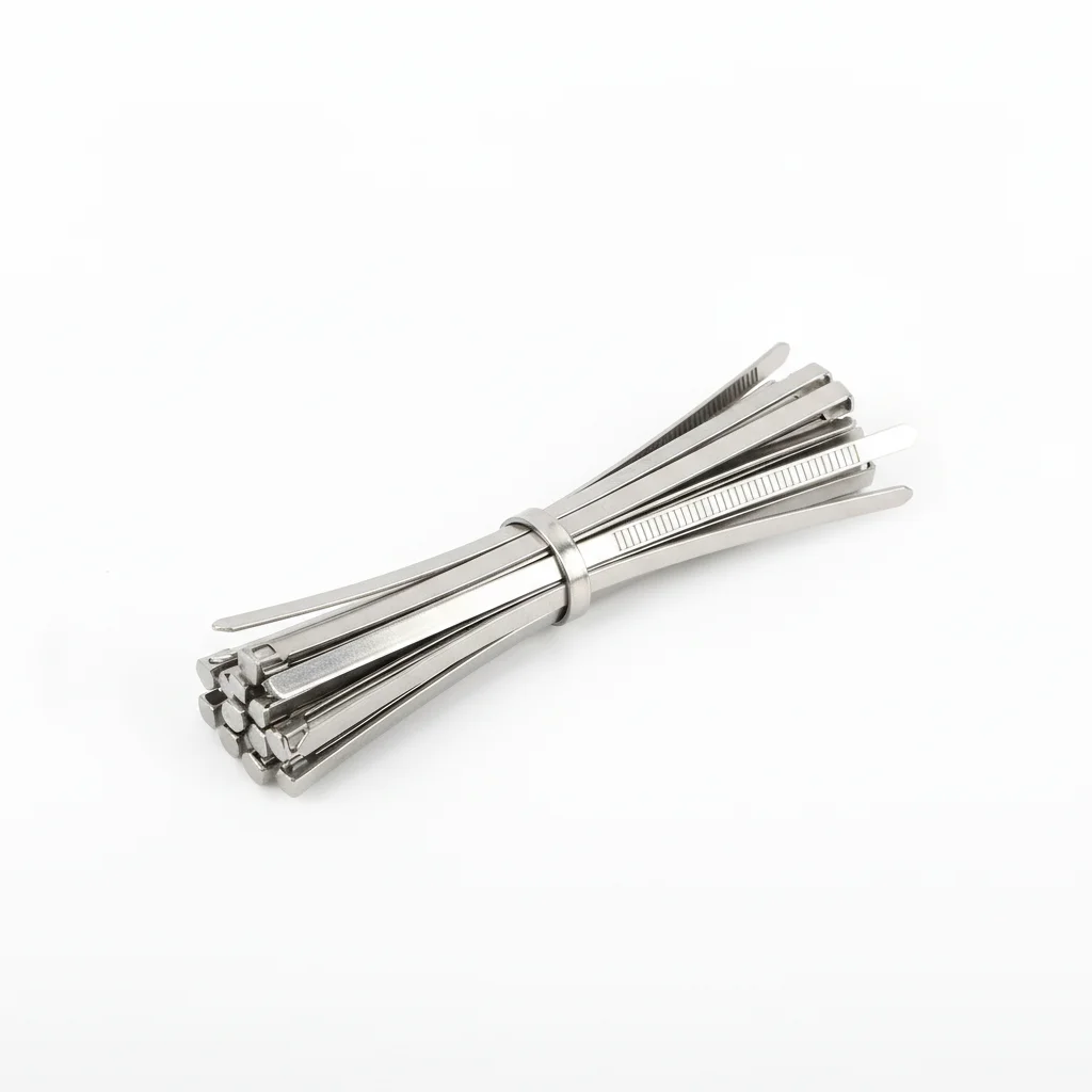
| PV Aluminum Alloy DC Cable | Nickel Plated Copper DC Cable | Cable Tie | Cable Gland | PV Specific Cable Trough/Cable Tray | |
|---|---|---|---|---|---|
| SPEC | 10/16/25mm² | 4/6/10mm² | 4.6×300mm | PG11-PG21 | FRP Fiberglass 100×50mm |
| MATERIAL | Aluminum Alloy Conductor (8030 grade) + XLPE + Double Jacket | Additional nickel plating layer over tinning + XLPE | 316 Stainless Steel (Uncoated) | 316 Stainless Steel + FFKM Perfluoroelastomer Seal | Fiber Reinforced Plastic (FRP) |
| GRADE | DC 2kV, 50% lighter than copper | Salt spray resistance 2000h (IEC 60068) | Seawater corrosion resistance 5000h salt spray | IP69K, Acid and Alkali Corrosion Resistant | Flame Retardant V0, Salt Spray Resistant 3000h |
| FINISH | HDG >=55um per ISO 1461 | HDG >=55um per ISO 1461 | HDG >=55um per ISO 1461 | HDG >=55um per ISO 1461 | HDG >=55um per ISO 1461 |
| CORROSION | C3 (ISO 12944-2) | C3 (ISO 12944-2) | C3 (ISO 12944-2) | C3 (ISO 12944-2) | C3 (ISO 12944-2) |
| TEMP | -20°C to +80°C | -20°C to +80°C | -20°C to +80°C | -20°C to +80°C | -20°C to +80°C |
| WEIGHT | ~0.5 kg/piece | ~0.5 kg/piece | ~0.5 kg/piece | ~0.5 kg/piece | ~0.5 kg/piece |
| MOQ | 100 pcs | 100 pcs | 100 pcs | 100 pcs | 100 pcs |
| PACK | VCI paper + carton | VCI paper + carton | VCI paper + carton | VCI paper + carton | VCI paper + carton |
| STD | ISO 898-1, GB/T 3098.1 | ISO 898-1, GB/T 3098.1 | ISO 898-1, GB/T 3098.1 | ISO 898-1, GB/T 3098.1 | ISO 898-1, GB/T 3098.1 |
| USE | Long distance string combining in coastal large power stations (weight reduction + salt spray resistance) | Offshore PV or C5 environment within 500m from shore | Cable fixing for offshore PV/chemical plants | Offshore platforms, chemical plants, C5-M environment | Centralized cable laying protection in coastal/chemical plants |
PROCEDURE
- Degrease cable entry and enclosure surfaces with MEK solvent. Verify surface roughness Ra <1.6um.
- Apply marine-grade anti-corrosion compound rated -50°C to 200°C. Use PTFE-encapsulated washers under 316 stainless steel gland.
- Install 316 stainless steel gland with FFKM seal, tighten to IP69K rating. Verify alignment to enclosure hole.
- Secure cable with 316 stainless steel ties at 4.6×300mm. Maintain drip loop before connector.
- Route cable through FRP trough, ensuring flame retardant V0 rating. Seal joints with approved sealant.
- PMI verify 10% of gland material for 316 stainless steel. Document for compliance audit.
COMMON ERRORS
| ✕ WRONG | CONSEQUENCE | ✓ CORRECT |
|---|---|---|
| Using brass gland in salt spray environment | Rapid corrosion of brass, leading to seal failure and water ingress. | Use 316 stainless steel gland with FFKM seal for salt spray resistance. |
| Tightening gland without proper torque | Over-compression damages FFKM seal, causing leakage. | Follow manufacturer's torque specification for IP69K rating. |
| Not using drip loop in coastal environment | Saltwater creeps along cable, corroding connector and causing ground fault. | Always form drip loop before gland entry to prevent water ingress. |
MAINTENANCE
Inspect glands and cable supports at each maintenance window. Replace any gland showing corrosion or seal degradation. Verify FFKM seal integrity. Check FRP trough for cracks. Document all findings.
SELECTION GUIDE
Still deciding between cable, gland, and tie configurations?
| Operating condition | Recommended option | Key basis |
|---|---|---|
| Inland, standard string spacing, laying distance ≤80m, string current <10A | Plan A: standard DC-side configuration — PV1-F single-core 4mm² (tinned copper + XLPE, DC 1.5kV) + double-core 2×4mm² + PA66 anti-UV cable tie (3.6×200mm, spacing ≤0.5m) + nylon gland (IP68) | C3 inland; 4mm² meets string-to-combiner-box runs ≤80m; nylon gland lowest cost |
| Large power station, distance >100m, or string >15A / high irradiance | Plan B: long-distance low-loss — reinforced 6/10mm² single-core + 2×6mm² LSZH double-core (IEC 60332-1) + 304 stainless-steel/epoxy tie + brass nickel-plated metal gland (IP68/IP69K, rodent-resistant) | C4 (ISO 12944-2); larger cross-section controls line loss; metal gland resists rodent damage |
| Coastal salt spray C5, desert high temperature, chemical plant, or UL export | Plan C: extreme environment — aluminum-alloy (8030) 10/16/25mm² double-jacket cable (DC 2kV, 50% lighter) + nickel-plated copper cable (salt spray 2000h, IEC 60068) + 316 SS uncoated tie (5000h) + 316 SS/FFKM gland (IP69K) | C5-M (ISO 12944-2); meets UL 4703 for North America; nickel/316 resists salt spray |
| Wire-diameter / voltage-drop sizing by laying distance and string current | <10A & <80m → 4mm²; 10-15A or 80-150m → 6mm²; >15A or >150m → 10mm² or larger | 4mm² over 100m exceeds the ≤1% voltage-drop standard of GB 50797 (can exceed 1.5%); line loss drops from ~3% to ~1.5% upgrading to 6mm² |
| Jacket aging / UV / temperature cycling and gland water ingress | Use PV-specific XLPE cross-linked jacket cable (compliant with EN 50618, -40°C to +120°C, UV aging test ≥720h); glands must be IP68 (2m/72h) with MC4 drip loop at connector end | Ordinary PVC jacket cracks within 3 years under UV; IEC 62930 statistics show ~11% of PV fires originate from DC cable faults; rain-water ingress triggers string ground alarm and shutdown |
REFERENCED STANDARDS
Referenced Standards and Authoritative References
European standard for PV DC cables, specifying performance requirements and test methods for conductors, insulation, and jackets.
Connectors for photovoltaic systems – Safety requirements and testsInternational standard for MC4 connectors, also a core reference standard for cable termination quality.
DC cables for photovoltaic systems – Halogen-free cross-linked polyolefin insulationLatest standard for PV DC cables, covering requirements for cross-linked polyolefin cables with XLPE insulation.
Photovoltaic Wire Standard (US Market)UL certification standard for PV cables in the North American market.
Polyvinyl chloride insulated cables of rated voltages up to and including 450/750V (China) and PV cablesCommon cable standard reference for domestic PV projects in China.
PV CablesSUPPLIER CAPABILITY
Quality, Delivery & Customization
Quality Control
- ✓MTC material certificates with every batch
- ✓Key parts sampled for hardness/salt spray/torque coefficient
- ✓100% inspection or AQL sampling before shipment
Delivery
- ✓Standard parts made to order: 7-15 days
- ✓Custom parts: 25-45 days
- ✓FOB/CIF/DDP supported
Customization
- ✓Drawing review and material matching
- ✓Non-standard sizes/heads/threads
- ✓Small-batch prototyping supported
Certification
- ✓Material certificates (MTC)
- ✓Spectrographic analysis reports
- ✓Salt spray test reports (on request)
MOQ: No MOQ for standard parts; custom parts assessed by process complexity
FAQ
Frequently Asked Questions
RELATED READING
Keep Reading & Next Step
NEXT: SELECTION & RFQ
PV Electrical ConnectorsFollow this page's selection path to the same-scenario RFQ page.
RELATED TOPIC
PV Electrical Connectors (MC4, etc.)RELATED TOPIC
Combiner Box HardwareBEYOND TECHNICAL SPECS
Finding the right factory, controlling quality, delivering on time — that's the real challenge. We cover fasteners, rubber, plastics, industrial textiles. One team, end to end.
SEE CAPABILITIES →