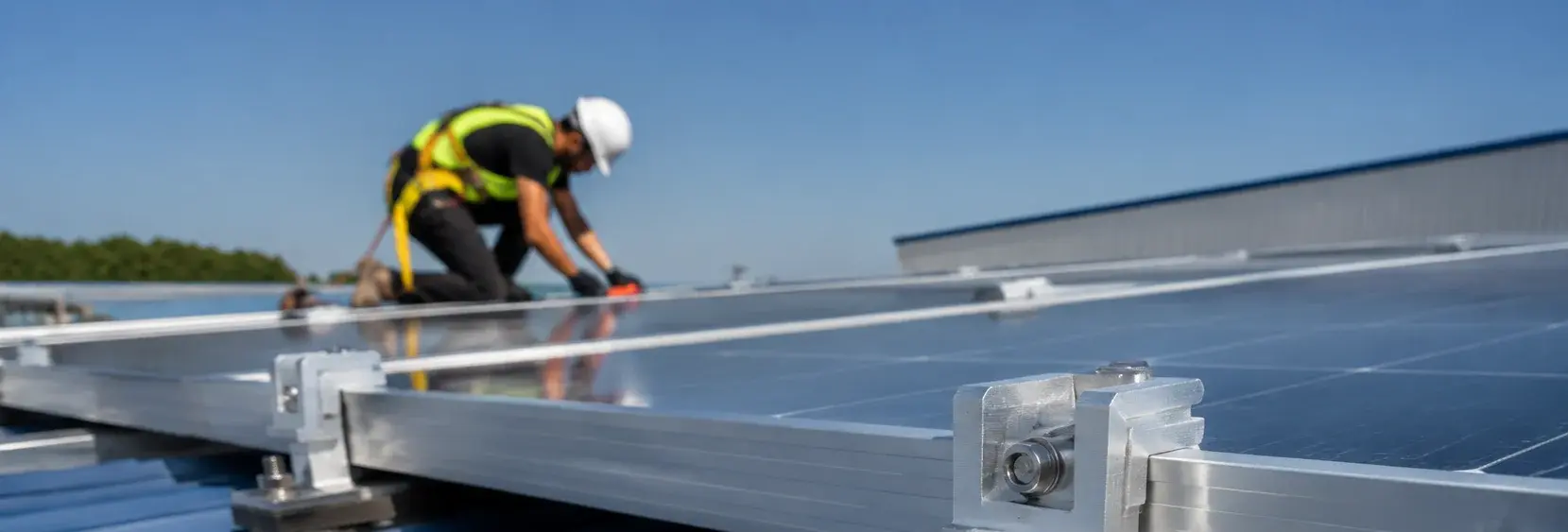
PV End and Mid Clamp Hardware: Aluminum vs Stainless Steel
PV clamps are the small hardware parts that hold module frames to rails. Material, grounding path and bolt stack matter because clamp failure can become a module retention problem under wind and maintenance loads
RISK AUDIT // ENGINEERING DIAGNOSIS
Procurement Pitfall Guide
"Three failure modes that send rooftop modules flying"
QC-AUDIT // REV.5
SCALE 1:1 · 03 ITEMS
RISK-01
Aluminum Clamp Deformation in High Wind Areas Causes Module Loosening
Corrective Measures
RISK-02
Fretting Wear Between Clamp and Module Frame Damages Frame
Corrective Measures
RISK-03
Mixing End and Mid Clamps Causes Edge Modules to Be Blown Off
Corrective Measures
FIELD-SPECIFIC INSIGHT
Clamp Procurement Is About Retention and Grounding Together
UL 2703's public scope connects PV mounting, clamping or retention devices and grounding or bonding devices. That means a clamp quote should not be checked as a simple metal clip; the retention path and bonding path need to be specified together
WHAT TO CHECK
- 1Separate end clamps from mid clamps because their module position and retention role are different
- 2Ask whether the clamp family also handles bonding or requires a separate grounding part
- 3Match aluminum or stainless hardware to roof exposure, rail material and washer stack
- 4Require drawings that show clamp height, bolt, washer and module-frame contact surface
| Check | Why it matters | What to specify |
|---|---|---|
| Retention role | End and mid clamps do not carry the same module-edge condition | End clamp, mid clamp, module frame height and rail profile |
| Grounding path | Some clamp systems combine retention with bonding; others require separate grounding hardware | Bonding method, grounding lug if needed and compatible washer or serrated feature |
| Material pairing | Clamp, bolt, rail and washer materials interact under corrosion and vibration | Clamp material, bolt material, washer type and surface finish |
Use UL 2703 as the scope reference for PV mounting, clamping, retention and grounding devices; project load values must come from the racking supplier
Evidence level: standard-backed
INDUSTRY TECH REFERENCE
End vs Mid Clamps: Position, Load, and Spec Differentials
The array edge takes the heaviest wind loads — end clamps need 20–30% more clamping capacity than mid clamps. Substituting mid clamps on the outermost row is a common reason edge modules get blown off.
| Type | Secures | Clamping requirement | Spec response |
|---|---|---|---|
| Mid clamp | The shared edge of two adjacent modules (T-bolt slides into the aluminum rail slot) | Baseline | Standard size (M8) |
| End clamp | The outer edge of a single edge-row module | 20–30% higher than mid clamp (empirical) | One size grade up from mid clamp (M8→M10) |
The 20–30% figure is empirical; sizing one grade up (M8→M10) follows the KB recommendation.
INDUSTRY TECH REFERENCE
Four Acceptance Checks for Clamps in High-Wind Zones
Applies to: clamp assemblies of aluminum clamps with 304 bolts; coastal and high-wind sites follow the reinforced specification.
- EPDM insulating shim ≥1 mm — breaks the galvanic couple between aluminum clamps and steel bolts, and cushions wind-vibration wear
- End clamps one size grade up from mid clamps (M8→M10); never substitute mid clamps on the outer row
- Quarterly hand-push check on the panel edge: re-torque if it moves more than 3 mm (suggested value)
- Coastal projects mandate 304 + EPDM insulation; a multi-MW array uses thousands of clamps per MW — order and inspect end and mid clamps separately, and rely on single-batch supply for consistent quality
The 3 mm movement threshold is a suggested value (quarterly check).
INDUSTRY TECH REFERENCE
The Forgotten Grounding Part: The Anodized Layer Is an Insulator
The anodized layer on a PV module's aluminum frame is an insulating Al₂O₃ ceramic — tightening a bolt against it does not ground the frame by default.
The <0.1Ω contact-resistance threshold and 2-year re-test follow the KB acceptance criteria.
PLAN COMPARISON
Three-Plan Core Parameter Comparison
Compare row by row. Click column headers to jump to plan details.
| A · Plan A · Standard Aluminum Clamp Configuration | B · Plan B · Reinforced Stainless Steel Clamp Configuration | C · Plan C · Lightweight Plastic Clamp (Non-Load Bearing) | |
|---|---|---|---|
| 1. ALUMINUM MID CLAMP | |||
| SPEC | 30-50mm Module Thickness | 30-50mm Module Thickness | 30-50mm |
| MATERIAL | 6063-T5 Aluminum, Anodized ≥15μm | 304 Stainless Steel | 316L |
| GRADE | Anodized | A2-70 | Electropolished |
| FINISH | HDG >=55um per ISO 1461 | HDG >=55um per ISO 1461 | HDG >=55um per ISO 1461 |
| 2. ALUMINUM END CLAMP | |||
| SPEC | 30-50mm Module Thickness | 30-50mm Module Thickness | 30-50mm |
| MATERIAL | 6063-T5 Aluminum, Anodized ≥15μm | 304 Stainless Steel | Ti6Al4V |
| GRADE | Anodized | A2-70 | — |
| FINISH | HDG >=55um per ISO 1461 | HDG >=55um per ISO 1461 | HDG >=55um per ISO 1461 |
| 3. BUFFER SHIM | |||
| SPEC | 0.8mm Thick | 1.0mm Thick | 1.0mm Thick |
| MATERIAL | EPDM | EPDM | EPDM+316L |
| GRADE | Black | Black | C5-M |
| FINISH | HDG >=55um per ISO 1461 | HDG >=55um per ISO 1461 | HDG >=55um per ISO 1461 |
SELECTION GUIDE
Still unsure which clamp plan fits your site?
| Operating condition | Recommended option | Key basis |
|---|---|---|
| Coastal (C4-C5) / high wind area, basic wind pressure ≥0.5 kN/m2 | Plan B · Reinforced Stainless Steel Clamp (304 A2-70) + Wedge Lock Washer | Stainless steel gives 2x strength and salt spray resistance; Dacromet wedge lock washer prevents loosening under wind vibration; verify loads per GB 50009 |
| Inland general roof, wind speed <30 m/s (C3) | Plan A · Standard Aluminum Clamp (6063-T5, anodized ≥15 μm) | Lightweight + non-corrosive + low cost; C3 per ISO 12944-2; aluminum clamps require grounding treatment because the anodized layer is insulating |
| Temporary / light structure (small roofs, carports, awning) | Plan C · Lightweight Plastic Clamp (Non-Load Bearing) | Lightweight and low cost for temporary structures; non-load-bearing and must meet module retention strength for the application |
Plan A · Standard Aluminum Clamp Configuration
C3 (ISO 12944-2) for inland low-wind sites
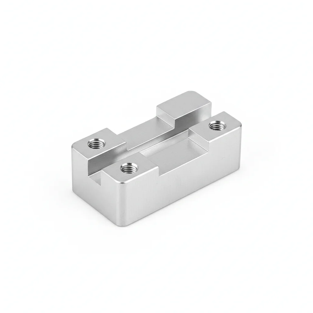
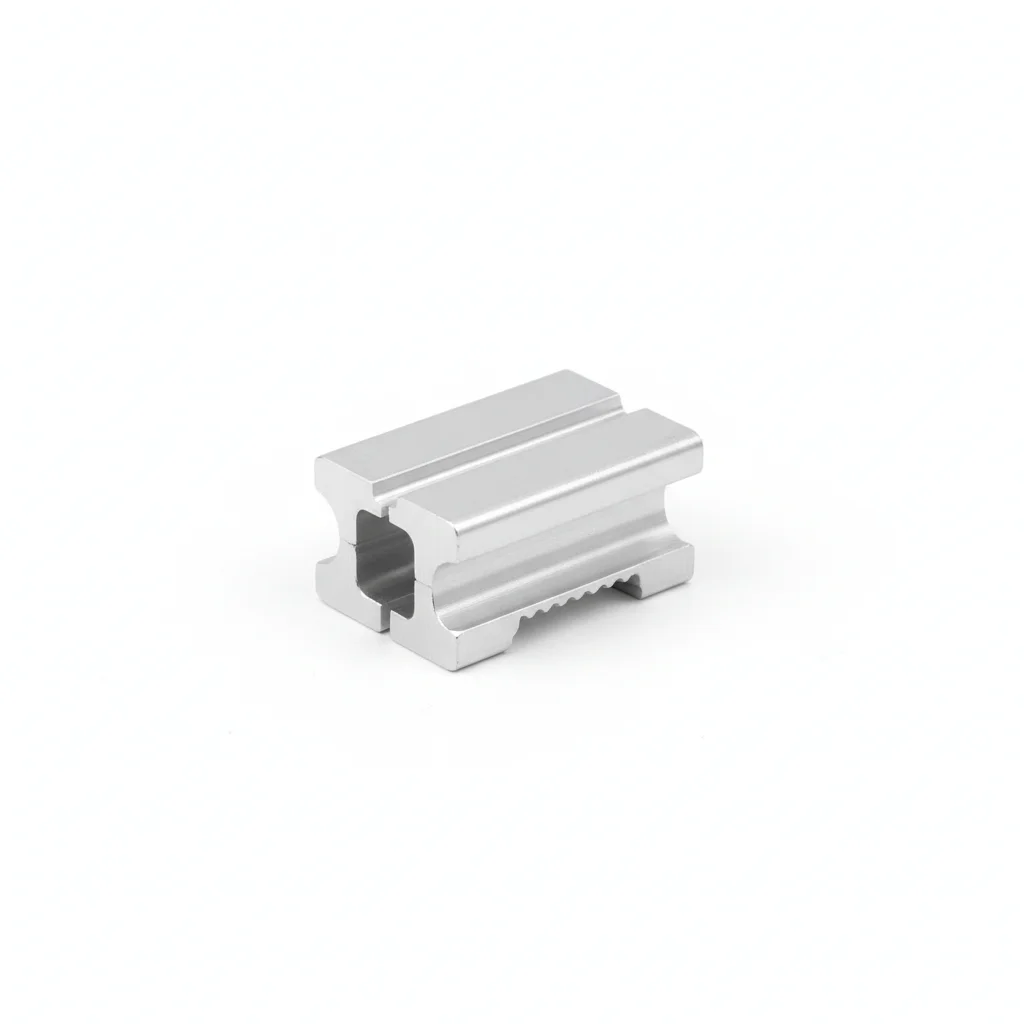
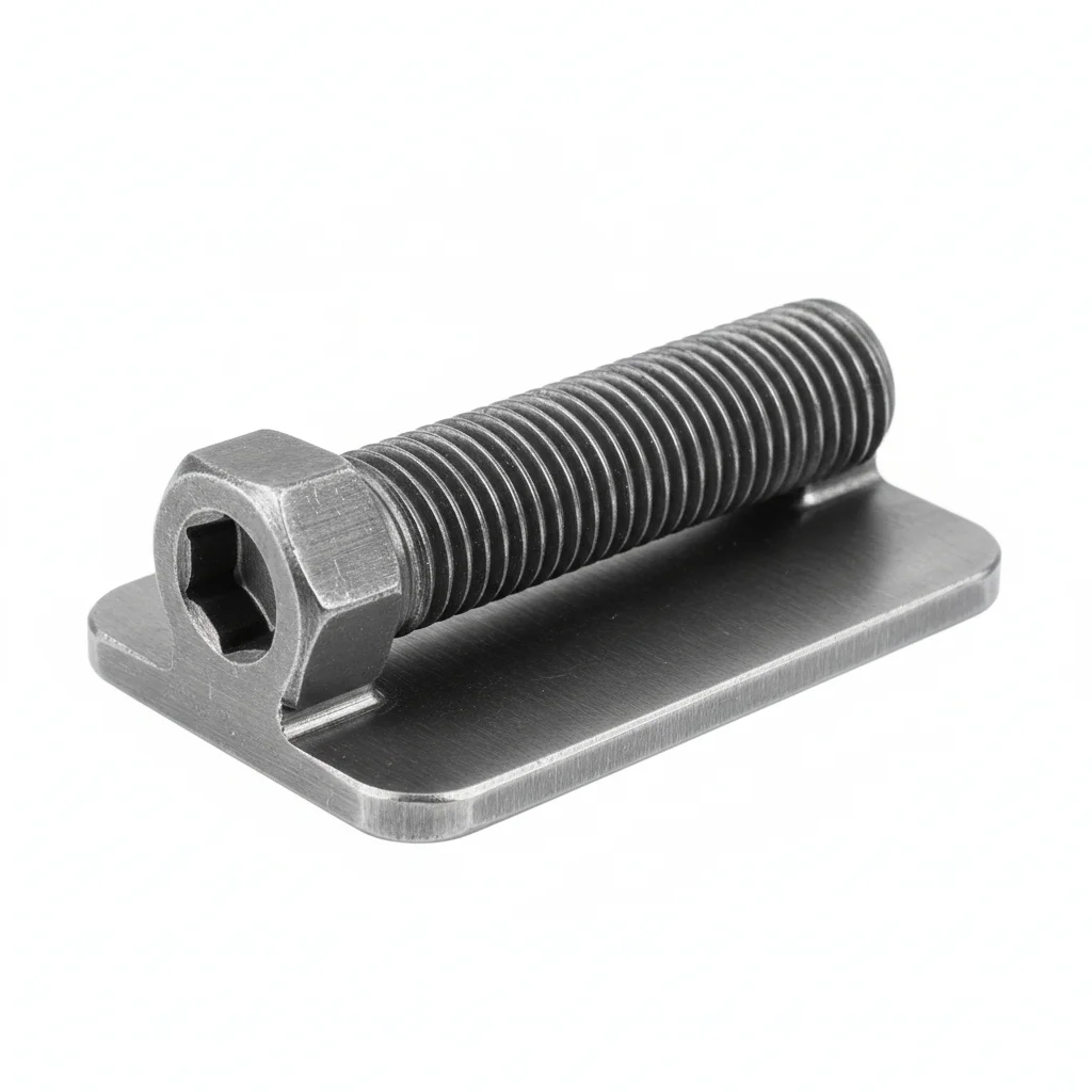
| Aluminum Mid Clamp | Aluminum End Clamp | Buffer Shim | M8 Stainless Steel Clamp Bolt | |
|---|---|---|---|---|
| SPEC | 30-50mm Module Thickness | 30-50mm Module Thickness | 0.8mm Thick | M8×25mm |
| MATERIAL | 6063-T5 Aluminum, Anodized ≥15μm | 6063-T5 Aluminum, Anodized ≥15μm | EPDM | 304 Stainless Steel |
| GRADE | Anodized | Anodized | Black | A2-70 |
| FINISH | HDG >=55um per ISO 1461 | HDG >=55um per ISO 1461 | HDG >=55um per ISO 1461 | HDG >=55um per ISO 1461 |
| CORROSION | C3 (ISO 12944-2) | C3 (ISO 12944-2) | C3 (ISO 12944-2) | C3 (ISO 12944-2) |
| TEMP | -20°C to +80°C | -20°C to +80°C | -20°C to +80°C | -20°C to +80°C |
| WEIGHT | ~0.5 kg/piece | ~0.5 kg/piece | ~0.5 kg/piece | ~0.5 kg/piece |
| MOQ | 100 pcs | 100 pcs | 100 pcs | 100 pcs |
| PACK | VCI paper + carton | VCI paper + carton | VCI paper + carton | VCI paper + carton |
| STD | ISO 898-1, GB/T 3098.1 | ISO 898-1, GB/T 3098.1 | ISO 898-1, GB/T 3098.1 | ISO 898-1, GB/T 3098.1 |
| USE | Secures two adjacent modules | Secures the outermost module | Cushion and anti-wear between clamp and frame | Connects clamp to rail |
PROCEDURE
- Inspect module frame thickness against the 30-50mm spec and confirm the clamp profile matches the rail groove before assembly.
- Slide the mid or end clamp over the module frame, insert the M8×25mm stainless bolt, and hand-tighten to hold position.
- Using a calibrated torque wrench, tighten aluminum clamps to 15-18Nm and stainless clamps to 22-25Nm; never exceed these values to avoid crushing the frame.
- Verify the clamp bite depth is at least 8mm on the module frame (over one-third of frame thickness) for edge rows.
- For the outermost row, confirm dedicated end clamps are used and double-bolt fixing is applied at ridge and eaves positions.
COMMON ERRORS
| ✕ WRONG | CONSEQUENCE | ✓ CORRECT |
|---|---|---|
| Using a mid clamp on the outermost row instead of an end clamp | Single-side clamping force drops to 50-60% of an end clamp, risking module blow-off under high winds (basic wind pressure ≥0.7kN/m²). | Always use dedicated end clamps for the array edge; ensure single-side clamping force is at least 300N. |
| Overtightening the M8 bolt beyond the recommended torque | Aluminum frame contact stress can exceed 250MPa, crushing the module frame and causing permanent damage. | Torque to 15-18Nm for aluminum clamps and 22-25Nm for stainless steel clamps using a calibrated torque wrench. |
| Skipping the EPDM buffer pad between clamp and module frame | Fretting wear removes the anodized layer, leading to frame corrosion and potential perforation over time. | Install a 0.5-1mm EPDM buffer pad to prevent metal-to-metal contact and provide vibration damping. |
MAINTENANCE
Inspect buffer pads at each overhaul window (typically every 5 years) and replace if hardened or cracked; check clamp torque seasonally, especially after high-wind events.
Plan B · Reinforced Stainless Steel Clamp Configuration
C4 Harsh per ISO 12944-2
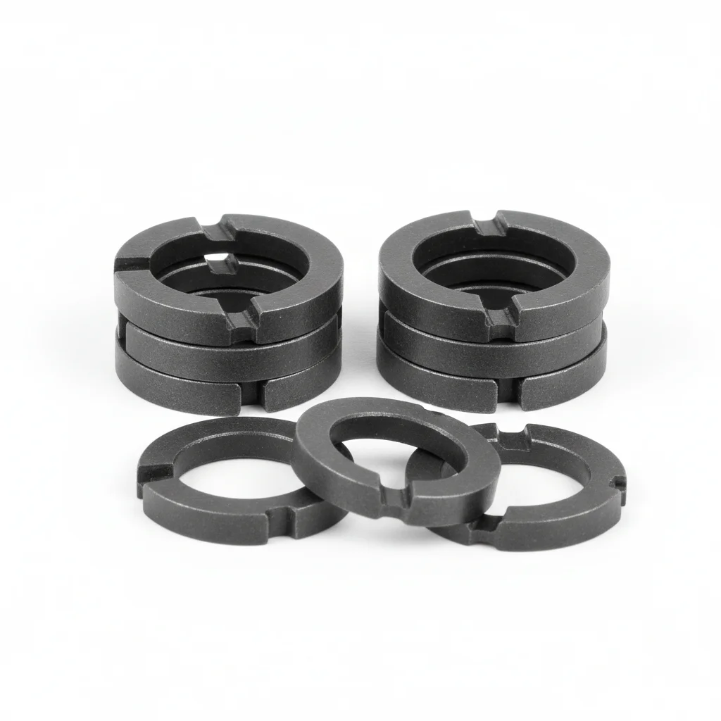
| Mid Clamp | End Clamp | Buffer Shim (Thickened) | Wedge Lock Washer / Anti-Loosening Washer | |
|---|---|---|---|---|
| SPEC | 30-50mm Module Thickness | 30-50mm Module Thickness | 1.0mm Thick | NL8 |
| MATERIAL | 304 Stainless Steel | 304 Stainless Steel | EPDM | Carbon Steel Quenched + Dacromet |
| GRADE | A2-70 | A2-70 | Black | Dacromet |
| FINISH | HDG >=55um per ISO 1461 | HDG >=55um per ISO 1461 | HDG >=55um per ISO 1461 | HDG >=55um per ISO 1461 |
| CORROSION | C3 (ISO 12944-2) | C3 (ISO 12944-2) | C3 (ISO 12944-2) | C3 (ISO 12944-2) |
| TEMP | -20°C to +80°C | -20°C to +80°C | -20°C to +80°C | -20°C to +80°C |
| WEIGHT | ~0.5 kg/piece | ~0.5 kg/piece | ~0.5 kg/piece | ~0.5 kg/piece |
| MOQ | 100 pcs | 100 pcs | 100 pcs | 100 pcs |
| PACK | VCI paper + carton | VCI paper + carton | VCI paper + carton | VCI paper + carton |
| STD | ISO 898-1, GB/T 3098.1 | ISO 898-1, GB/T 3098.1 | ISO 898-1, GB/T 3098.1 | ISO 898-1, GB/T 3098.1 |
| USE | Module fixing in high wind areas | Outer module fixing in high wind areas | Enhanced cushioning for high wind areas | Prevents clamp loosening under wind vibration |
PROCEDURE
- Degrease the clamp contact area and module frame with acetone; verify surface roughness Ra <3.2μm.
- Fit the 1.0mm EPDM buffer shim between clamp and frame; position the wedge lock washer under the nut.
- Hand-tighten the M8 A2-70 bolts, then torque to 22-25 Nm in a cross pattern using a calibrated wrench.
- Verify bite depth ≥8mm on end clamps; for mid clamps, ensure equal pressure on both module frames.
- Perform a slip test on 5% of installed clamps by applying 500N lateral force; the module must not shift.
- Mark the bolt heads with torque seal paint and log the installation date and torque values for each row.
COMMON ERRORS
| ✕ WRONG | CONSEQUENCE | ✓ CORRECT |
|---|---|---|
| Using an aluminum mid clamp on the outermost row instead of a dedicated end clamp | Single-side clamping force drops to 50-60% of an end clamp, so edge modules can lift off under wind uplift ≥0.5kN/m². | Always use the 304 stainless steel end clamp on the outer row; verify the bite depth is ≥8mm. |
| Overtightening the M8 stainless bolt beyond 25 Nm | The module frame can crush (contact stress exceeds ~200MPa), weakening retention and voiding the warranty. | Torque to the specified 22-25 Nm with a calibrated wrench; never exceed the upper limit. |
| Skipping the wedge lock washer on the bolt | Wind vibration can back off the nut, reducing clamp force and causing module rattling or loosening over time. | Install the NL8 wedge lock washer (Dacromet-coated) under the nut to maintain preload under vibration. |
MAINTENANCE
Seasonally inspect clamps for loosening and corrosion, especially after storms. Re-torque any bolt below 80% of the 22-25 Nm spec. Replace the EPDM shim if hardened or cracked. Every 5 years, replace the wedge lock washers and buffer shims as part of routine upkeep.
Plan C · Lightweight Plastic Clamp (Non-Load Bearing)
C5-M Extreme per ISO 12944-2
| Mid Clamp | Titanium Alloy End Clamp | Buffer Shim | |
|---|---|---|---|
| SPEC | 30-50mm | 30-50mm | 1.0mm Thick |
| MATERIAL | 316L | Ti6Al4V | EPDM+316L |
| GRADE | Electropolished | — | C5-M |
| FINISH | HDG >=55um per ISO 1461 | HDG >=55um per ISO 1461 | HDG >=55um per ISO 1461 |
| CORROSION | C3 (ISO 12944-2) | C3 (ISO 12944-2) | C3 (ISO 12944-2) |
| TEMP | -20°C to +80°C | -20°C to +80°C | -20°C to +80°C |
| WEIGHT | ~0.5 kg/piece | ~0.5 kg/piece | ~0.5 kg/piece |
| MOQ | 100 pcs | 100 pcs | 100 pcs |
| PACK | VCI paper + carton | VCI paper + carton | VCI paper + carton |
| STD | ISO 898-1, GB/T 3098.1 | ISO 898-1, GB/T 3098.1 | ISO 898-1, GB/T 3098.1 |
| USE | Offshore platform clamp | Highest corrosion protection level | Cushioning for offshore environments |
PROCEDURE
- Degrease the clamp and frame surfaces with MEK solvent; verify surface roughness Ra <1.6μm.
- Place the 1.0mm EPDM+316L buffer shim between clamp and module frame to isolate dissimilar metals.
- Position the titanium end clamp or 316L mid clamp, aligning within 0.3mm; use PTFE-encapsulated washers under the bolt head and nut.
- Tighten bolts gradually in a star pattern to the recommended torque for 316L (22-25 Nm, as per plan B) using a calibrated wrench.
- Perform a pull test on 5% of clamps to 80% of proof load; replace any that slip or deform.
- Apply a marine-grade sealant over the bolt heads and record installation data for the compliance audit.
COMMON ERRORS
| ✕ WRONG | CONSEQUENCE | ✓ CORRECT |
|---|---|---|
| Using standard 304 stainless bolts in a C5-M coastal environment | 304 has a chloride pitting threshold of only 100ppm, so sea salt spray causes pitting and crevice corrosion within months. | Use 316L stainless steel bolts or titanium alloy hardware for the clamp assembly to resist chloride attack. |
| Mixing aluminum clamps with stainless steel bolts without an isolating shim | Galvanic corrosion eats away the aluminum clamp contact surface by 0.2-0.5mm over 3-5 years, causing clamp loosening. | Use the EPDM+316L buffer shim to separate dissimilar metals and prevent galvanic corrosion. |
| Overtightening the clamp bolt beyond the recommended torque | The module frame can crack or deform under excessive clamping pressure, especially with thin frames. | Torque to the specified range (22-25 Nm for stainless) using a calibrated wrench; never exceed the limit. |
MAINTENANCE
Inspect clamps at each overhaul window for signs of pitting, crevice corrosion, or shim degradation. Re-torque any bolt that has lost more than 15% of its specified tension. Replace buffer shims if they show hardening or cracking. Every 5 years, replace all critical fasteners and shims to maintain integrity.
REFERENCED STANDARDS
Referenced Standards & Authoritative References
SUPPLIER CAPABILITY
Quality, Delivery & Customization
Quality Control
- ✓MTC material certificates with every batch
- ✓Key parts sampled for hardness/salt spray/torque coefficient
- ✓100% inspection or AQL sampling before shipment
Delivery
- ✓Standard parts made to order: 7-15 days
- ✓Custom parts: 25-45 days
- ✓FOB/CIF/DDP supported
Customization
- ✓Drawing review and material matching
- ✓Non-standard sizes/heads/threads
- ✓Small-batch prototyping supported
Certification
- ✓Material certificates (MTC)
- ✓Spectrographic analysis reports
- ✓Salt spray test reports (on request)
MOQ: No MOQ for standard parts; custom parts assessed by process complexity
FAQ
Frequently Asked Questions
RELATED READING
Keep Reading & Next Step
BEYOND TECHNICAL SPECS
Finding the right factory, controlling quality, delivering on time — that's the real challenge. We cover fasteners, rubber, plastics, industrial textiles. One team, end to end.
SEE CAPABILITIES →