Rail Splice Failure in Rooftop PV: Connector Selection to Prevent Misalignment and Corrosion
Rail connectors are the critical joint between rail sections. A loose connector leads to rail misalignment, uneven clamp force, and module micro-cracks. In a 5MW rooftop plant, over 2000 connectors are used; batch selection risk is amplified. This page failure mechanisms and procurement checks for aluminum vs stainless steel connectors, bolt loosening under wind vibration, and galvanic corrosion prevention
RISK AUDIT // ENGINEERING DIAGNOSIS
Procurement Pitfall Guide
"Connector gaps, galvanic couples, and loose bolts—these are the failure points that silently compromise rooftop PV structures."
QC-AUDIT // REV.5
SCALE 1:1 · 03 ITEMS
RISK-01
Poor Rail Connection Leads to Accumulated Module Installation Deviation
Corrective Measures
RISK-02
Mixing Aluminum and Stainless Steel Rail Connectors Causes Galvanic Corrosion
Corrective Measures
RISK-03
Connector Bolts Loosen Under Wind Vibration, Causing Rail System Instability
Corrective Measures
FIELD-SPECIFIC INSIGHT
Rail Connector Procurement Checklist: 4 Failure Points to Verify
Rail connectors are often treated as simple splice parts, but they bear structural continuity and straightness of the entire rail system. The most overlooked engineering difference is the galvanic corrosion risk when mixing aluminum rails with stainless steel connectors, and the cascading failure from a single loose bolt under wind vibration
WHAT TO CHECK
- 1Connector gap >1mm or loose → rail straightness deviation accumulates → clamp misalignment → module micro-cracks. Specify max gap and torque verification
- 2Aluminum rail + stainless steel connector without insulation → galvanic corrosion in rain/condensation → white powdery Al₂O₃ on rail surface within 2-3 years. Require insulating shim and bolt sleeve
- 3Wind vibration causes connector bolt preload loss → cascading failure of adjacent connectors. Use wedge lock washers or disc springs in typhoon zones
- 4Mixing aluminum and stainless steel connectors in same system accelerates galvanic corrosion. Specify same-metal connectors or add isolation for dissimilar metals
| Check | Why it matters | What to specify |
|---|---|---|
| Connector gap and straightness | Gap >1mm or loose connector causes rail deviation, leading to clamp misalignment and module micro-cracks | Torque bolts to manufacturer spec; verify rail straightness after installation |
| Galvanic corrosion prevention | Aluminum rail + stainless steel connector forms galvanic cell; corrosion appears within 2-3 years in wet environments | Use insulating shim (≥0.5mm PVC) between rail and connector; nylon bolt sleeve for bolt holes |
| Bolt anti-loosening under vibration | Wind loads cause bolt preload loss; one loose bolt doubles load on adjacent connectors, risking cascading failure | Use wedge lock washers or disc spring washers; specify re-torque after first wind event |
| Material compatibility | Mixing aluminum and stainless steel connectors in same system increases galvanic corrosion risk | Torque bolts to manufacturer spec using a torque wrench; perform periodic rechecks and verify rail straightness after installation |
Data based on page content: connector gap >1mm, galvanic corrosion timeline 2-3 years, wind vibration loosening. Verify specific torque values and corrosion rates with supplier test reports
Evidence level: source-page-only
INDUSTRY TECH REFERENCE
Fixed vs Sliding Splices: How They Are Laid Out
Rails ship in sections (3–6 m per piece) and are spliced on site. A 6 m section moves about 6.9 mm over a 50°C swing (aluminum α = 23×10⁻⁶/°C) — the sliding splice is the outlet for that movement.
| Splice | Job | Placement rule |
|---|---|---|
| Fixed splice | Load-carrying joint, locks the rail axially | Used at most positions |
| Sliding splice (slotted hole) | Lets the rail move axially and absorbs thermal expansion | One every 3–4 sections; fixed:sliding ≈3:1 |
| All fixed (no sliding splice) | Rail has nowhere to grow and flexes under the 50°C swing | Clamps loosen → cascading failure |
Fixed:sliding ≈3:1 with one sliding splice every 3–4 sections follows the KB recommendation; 6.9 mm is the re-verified calculation (23×10⁻⁶/°C × 6 m × 50°C).
INDUSTRY TECH REFERENCE
One Loose Splice, Whole Row Down: The Domino Path
A loose rail splice rarely stops at one joint — it propagates along the rail. Example: one row of rooftop PV rails.
- 1A splice bolt loosens (under-torqued or preload decay), and the connector starts moving against the rail
- 2A step appears at the joint — the clamping load on neighboring clamps goes uneven
- 3Unevenly loaded clamps lose grip and loosen in turn
- 4The loosening cascades along the rail in both directions as clamping force fades across the row
- 5In strong wind the whole row of modules and rails detaches — not one failed point, one failed line
The cascade follows KB §2.3 (one loose connector → rail step → uneven clamp load → chain loosening → whole-row detach in wind); this chain carries no standalone magnitude figures.
INDUSTRY TECH REFERENCE
Splice Layout Acceptance: Count Fixed and Sliding First
Run these four checks at acceptance, before torque discussions — a wrong layout defeats any torque accuracy.
- Count the ratio: fixed:sliding ≈3:1, at least one sliding splice (slotted hole) every 3–4 sections — check the layout drawing before the crew starts
- Prove the sliding splice slides: after torquing, the slotted hole must still allow axial movement — a locked sliding splice is just another fixed one
- Verify against the expansion budget: a 6 m section moves ≈6.9 mm over a 50°C swing; the sliding travel must exceed that movement
- Found one loose splice? Don't just replace it — check whether neighboring clamps are already unevenly loaded and assess the whole run for cascade risk
6.9 mm is the re-verified calculation; ≈3:1 and one sliding splice per 3–4 sections follow the KB recommendation.
INDUSTRY TECH REFERENCE
Why Aluminum Rails Must Not Touch Stainless Steel
Before two metals touch, confirm whether the site is coastal.
Aluminum rails in direct contact with stainless steel bolts or connectors make aluminum the anode and stainless the cathode — in humid coastal air (Cl⁻ deposition from ISO 9223 S2 upward) this galvanic couple corrodes aluminum faster, and pits around bolted joints can reach 2 mm+ within 3 years (magnitude estimate). Same-metal pairs (aluminum–aluminum) avoid this entirely — the simplest inland choice. When stainless parts are unavoidable, isolate the interface with an EPDM insulating shim (≥1 mm) and insulate bolt holes to break the galvanic path.
The 3-year/2 mm+ figure is a magnitude estimate (marked as such in the KB); the ≥1 mm EPDM shim follows the clamp-pad spec (§2.2), applied here to splices under the same galvanic mechanism.
PLAN COMPARISON
Three-Plan Core Parameter Comparison
Compare row by row. Click column headers to jump to plan details.
| A · Plan A · Aluminum Rail + Aluminum Connector Standard Plan | B · Plan B · Stainless Steel Connector + Insulation Isolation | C · Plan C · Harsh Environment / Wedge Lock Washer Anti-Loosening | |
|---|---|---|---|
| 1. ALUMINUM ALLOY RAIL CONNECTOR | |||
| SPEC | Compatible with C-channel rail, Length 100-150mm | Compatible with C-channel rail | Extended type 200mm |
| MATERIAL | 6063-T5 Aluminum Alloy | 304/316 Stainless Steel | 316L Stainless Steel |
| GRADE | Anodized ≥15μm | Natural Finish | Electropolished |
| FINISH | HDG >=55um per ISO 1461 | HDG >=55um per ISO 1461 | HDG >=55um per ISO 1461 |
| 2. ALUMINUM CONNECTOR MATCHING BOLT | |||
| SPEC | M8×20mm | Thickness ≥0.5mm | NL8 |
| MATERIAL | 304 Stainless Steel | PVC | 316L |
| GRADE | A2-70 | Insulating | Dacromet |
| FINISH | HDG >=55um per ISO 1461 | HDG >=55um per ISO 1461 | HDG >=55um per ISO 1461 |
| 3. LOCK NUT | |||
| SPEC | M8 | Compatible with M8 bolt | M8 Disc Spring |
| MATERIAL | 304 Stainless Steel | Nylon PA66 | 65Mn |
| GRADE | Nylon Insert | Insulating | Dacromet |
| FINISH | HDG >=55um per ISO 1461 | HDG >=55um per ISO 1461 | HDG >=55um per ISO 1461 |
SELECTION GUIDE
Which Rail Connector Plan Fits Your Site?
| Operating condition | Recommended option | Key basis |
|---|---|---|
| Aluminum rail system, inland C3 environment | Plan A · Aluminum Rail + Aluminum Connector (6063-T5, anodized ≥15 μm) | Same-metal connection avoids galvanic corrosion; aluminum connectors are ~40% cheaper than stainless steel; C3 per ISO 12944-2 |
| Coastal C4-C5 zone / rail systems already using stainless steel connectors | Plan B · Stainless Steel Connector + Insulation Isolation | Add PVC insulating shim (≥0.5 mm) plus nylon bolt sleeve to break the galvanic circuit; C4 harsh per ISO 12944-2 |
| Frequent typhoon area / extreme temperature difference zone | Plan C · Wedge Lock Washer Anti-Loosening + Compensation Shim | Use wedge lock washers or disc springs to prevent preload loss; M8 recommended 15-20 Nm; C5-M extreme per ISO 12944-2 |
Plan A · Aluminum Rail + Aluminum Connector Standard Plan
C3 Standard per ISO 12944-2
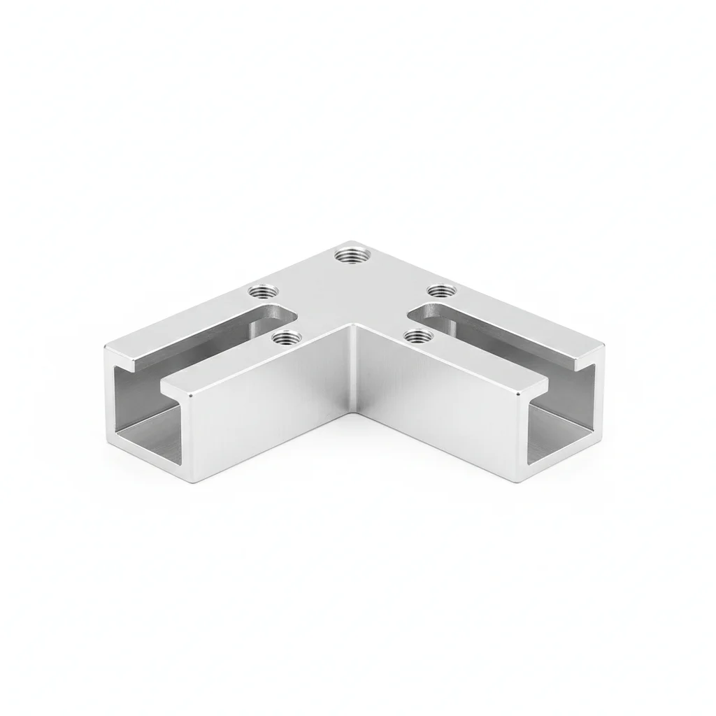
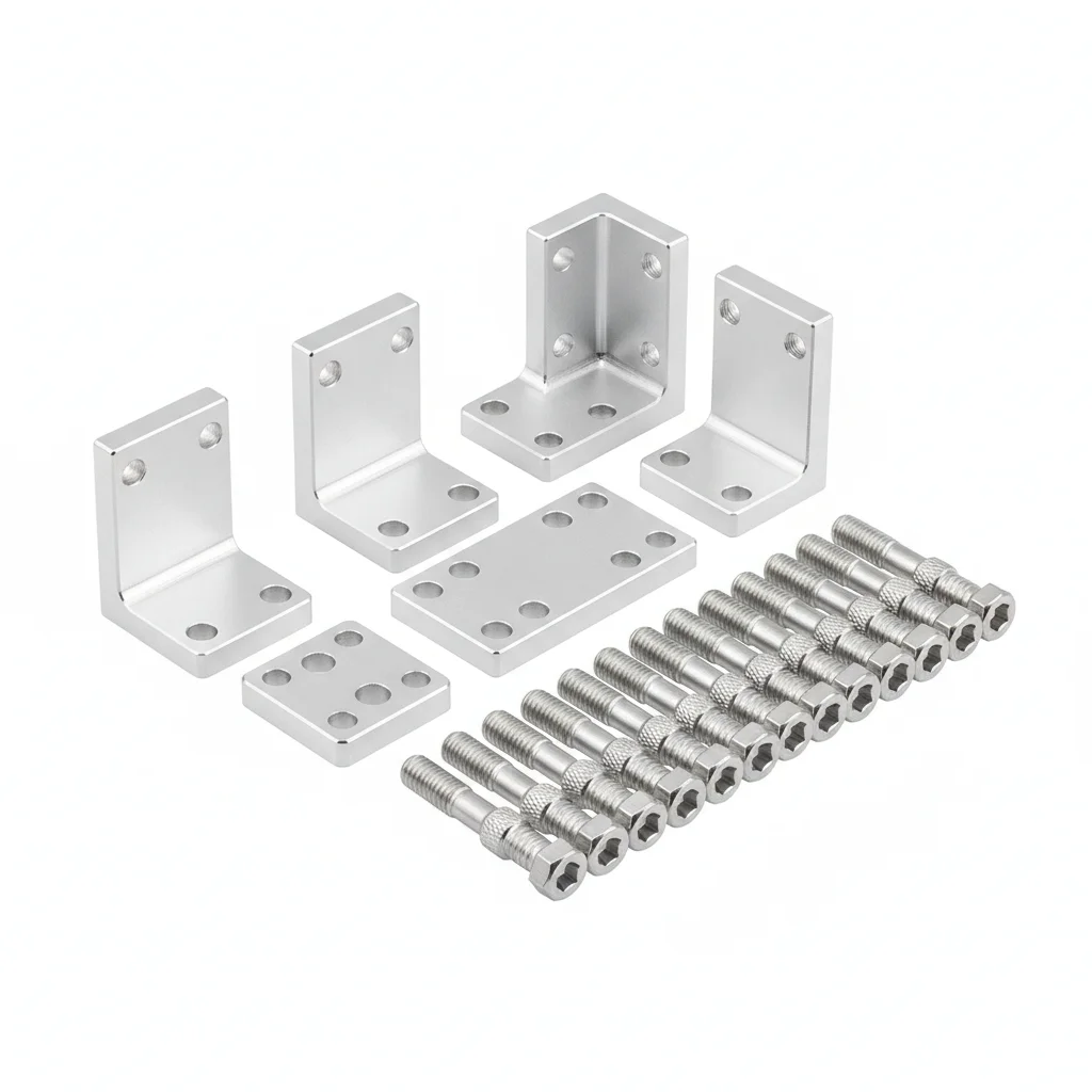
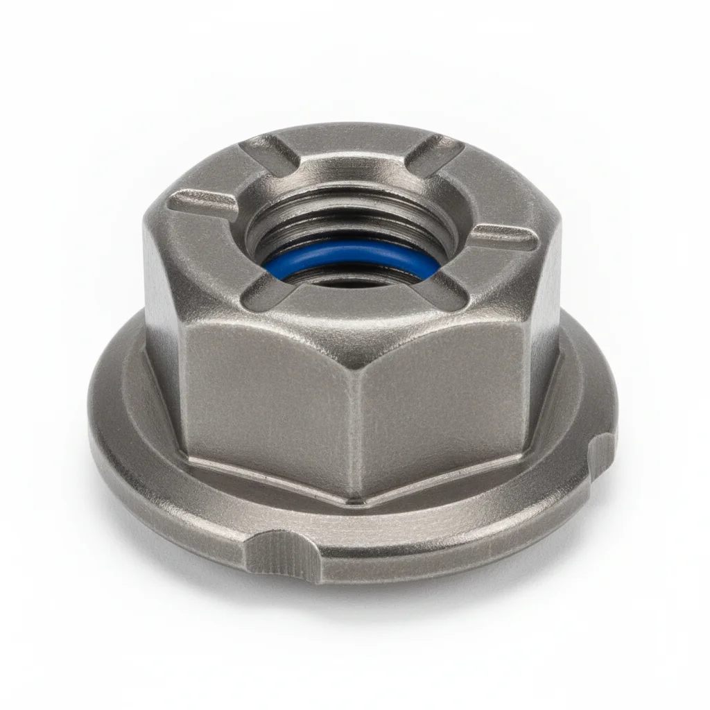
| Aluminum Alloy Rail Connector | Aluminum Connector Matching Bolt | Lock Nut | |
|---|---|---|---|
| SPEC | Compatible with C-channel rail, Length 100-150mm | M8×20mm | M8 |
| MATERIAL | 6063-T5 Aluminum Alloy | 304 Stainless Steel | 304 Stainless Steel |
| GRADE | Anodized ≥15μm | A2-70 | Nylon Insert |
| FINISH | HDG >=55um per ISO 1461 | HDG >=55um per ISO 1461 | HDG >=55um per ISO 1461 |
| CORROSION | C3 (ISO 12944-2) | C3 (ISO 12944-2) | C3 (ISO 12944-2) |
| TEMP | -20°C to +80°C | -20°C to +80°C | -20°C to +80°C |
| WEIGHT | ~0.5 kg/piece | ~0.5 kg/piece | ~0.5 kg/piece |
| MOQ | 100 pcs | 100 pcs | 100 pcs |
| PACK | VCI paper + carton | VCI paper + carton | VCI paper + carton |
| STD | ISO 898-1, GB/T 3098.1 | ISO 898-1, GB/T 3098.1 | ISO 898-1, GB/T 3098.1 |
| USE | Aluminum rail splicing connection | Connector fixing | Matching connecting bolt |
PROCEDURE
- Clean rail splice surfaces with a lint-free cloth and isopropyl alcohol to remove any residue that could compromise the anodized layer.
- Slide the 6063-T5 aluminum connector into the C-channel rail, ensuring each rail end inserts at least 50mm and the 3-5mm thermal expansion gap is maintained.
- Pre-tighten the M8×20 A2-70 bolts to position the connector, then verify rail straightness with a level before final locking.
- Torque the M8 bolts to 15-18Nm using a calibrated wrench, alternating between bolts to seat the connector evenly against the rail.
- Fit the M8 nylon insert lock nuts and re-check torque after the first wind event or thermal cycle to account for initial seating.
COMMON ERRORS
| ✕ WRONG | CONSEQUENCE | ✓ CORRECT |
|---|---|---|
| Using a stainless steel connector directly on an aluminum rail without isolation | Galvanic corrosion forms at the contact surfaces, producing white Al₂O₃ powder on the aluminum rail within 2-3 years in wet conditions. | Stick with the same-metal aluminum connector of Plan A, or if stainless is unavoidable, add PVC insulating shims ≥0.5mm and nylon bolt sleeves to break the galvanic circuit. |
| Overtightening the M8 bolts beyond the recommended 15-18Nm | Threads strip or the aluminum connector distorts, causing uneven clamp force and rail misalignment that leads to module micro-cracks. | Use a calibrated torque wrench set to 15-18Nm and verify with a torque audit on a 5% sample after installation. |
| Forgetting to leave the 3-5mm thermal expansion gap at the rail joint | Thermal expansion of the aluminum rail (23×10⁻⁶/°C) over a 50°C swing can bend the rail, creating an uneven mounting surface and risking module breakage. | Position the connector so one rail end is fixed by the bolt and the other slides, maintaining the 3-5mm gap as specified. |
MAINTENANCE
Inspect the connector bolts and rail joints annually before typhoon season, checking for any loosening or corrosion on the anodized surface. Re-torque any M8 bolts that have dropped below 80% of the 15-18Nm specification. Replace connectors showing pitting or corrosion affecting more than 5% of the surface area.
Plan B · Stainless Steel Connector + Insulation Isolation
C4 Harsh per ISO 12944-2
| Rail Connector | Insulating Shim | Nylon Insulation Bolt Sleeve | |
|---|---|---|---|
| SPEC | Compatible with C-channel rail | Thickness ≥0.5mm | Compatible with M8 bolt |
| MATERIAL | 304/316 Stainless Steel | PVC | Nylon PA66 |
| GRADE | Natural Finish | Insulating | Insulating |
| FINISH | HDG >=55um per ISO 1461 | HDG >=55um per ISO 1461 | HDG >=55um per ISO 1461 |
| CORROSION | C3 (ISO 12944-2) | C3 (ISO 12944-2) | C3 (ISO 12944-2) |
| TEMP | -20°C to +80°C | -20°C to +80°C | -20°C to +80°C |
| WEIGHT | ~0.5 kg/piece | ~0.5 kg/piece | ~0.5 kg/piece |
| MOQ | 100 pcs | 100 pcs | 100 pcs |
| PACK | VCI paper + carton | VCI paper + carton | VCI paper + carton |
| STD | ISO 898-1, GB/T 3098.1 | ISO 898-1, GB/T 3098.1 | ISO 898-1, GB/T 3098.1 |
| USE | Coastal rail connection | Isolation between aluminum rail and stainless steel connector | Isolation between bolt and aluminum rail |
PROCEDURE
- Degrease the aluminum rail contact area and stainless steel connector with acetone; verify surface roughness Ra <3.2μm.
- Place a PVC insulating shim (≥0.5mm thick) between the rail and connector, and insert a nylon PA66 sleeve over each M8 bolt.
- Align the connector within the rail channel, ensuring a 3–5mm expansion gap at the joint; pre-tighten bolts for positioning.
- Tighten the M8 stainless steel bolts in a cross pattern to the recommended torque (20–22Nm for stainless steel connectors), using a calibrated wrench.
- Verify that the insulating shim fully covers the mating surfaces and that no bare metal contact exists between aluminum and stainless steel.
- Record torque values and installation date; inspect for any gaps or misalignment exceeding 0.5mm.
COMMON ERRORS
| ✕ WRONG | CONSEQUENCE | ✓ CORRECT |
|---|---|---|
| Omitting the insulating shim or bolt sleeve when joining aluminum rails with stainless steel connectors | Galvanic corrosion initiates within 2-3 years, producing white powdery Al₂O₃ on the aluminum rail and weakening the joint. | Always install a PVC shim (≥0.5mm) and nylon sleeve to electrically isolate the dissimilar metals. |
| Forgetting to leave a thermal expansion gap at the connector joint | Thermal cycling (aluminum coefficient 23×10⁻⁶/°C) causes rail buckling or bolt loosening, leading to misalignment. | Leave a 3-5mm gap between rail ends inside the connector to accommodate expansion. |
| Using ordinary bolts instead of stainless steel with nylon lock nuts | Corrosion and vibration cause preload loss, resulting in loose connectors and rail instability under wind loads. | Use 304 stainless steel bolts (A2-70) with nylon insert lock nuts (GB/T 889.1) and stainless steel flat washers. |
MAINTENANCE
Before each typhoon season, recheck torque on all connector bolts (M8 stainless steel recommended 20-22Nm) and inspect for any signs of galvanic corrosion. Replace any insulating shims that show wear or degradation. If white powdery corrosion appears, disassemble, clean, and re-install with new isolation components.
Plan C · Harsh Environment / Wedge Lock Washer Anti-Loosening
C5-M Extreme per ISO 12944-2
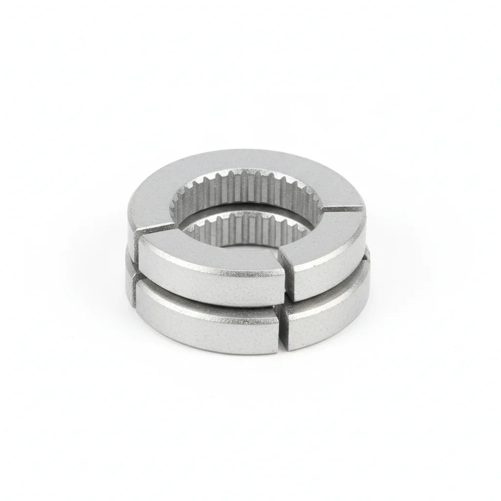
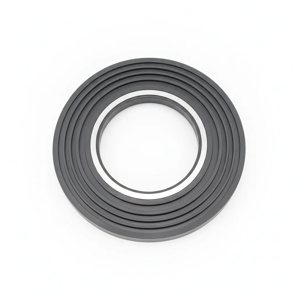
| Rail Connector | Wedge Lock Washer Anti-Loosening Washer | Elastic Compensation Shim | |
|---|---|---|---|
| SPEC | Extended type 200mm | NL8 | M8 Disc Spring |
| MATERIAL | 316L Stainless Steel | 316L | 65Mn |
| GRADE | Electropolished | Dacromet | Dacromet |
| FINISH | HDG >=55um per ISO 1461 | HDG >=55um per ISO 1461 | HDG >=55um per ISO 1461 |
| CORROSION | C3 (ISO 12944-2) | C3 (ISO 12944-2) | C3 (ISO 12944-2) |
| TEMP | -20°C to +80°C | -20°C to +80°C | -20°C to +80°C |
| WEIGHT | ~0.5 kg/piece | ~0.5 kg/piece | ~0.5 kg/piece |
| MOQ | 100 pcs | 100 pcs | 100 pcs |
| PACK | VCI paper + carton | VCI paper + carton | VCI paper + carton |
| STD | ISO 898-1, GB/T 3098.1 | ISO 898-1, GB/T 3098.1 | ISO 898-1, GB/T 3098.1 |
| USE | Typhoon and C5-M environment | Replaces standard spring washer | Compensates for thermal expansion/contraction displacement |
PROCEDURE
- Clean the rail and connector surfaces with MEK solvent; verify surface roughness Ra <1.6μm for optimal wedge lock engagement.
- Apply a marine-grade anti-corrosion compound rated for -50°C to 200°C to all threads and mating surfaces.
- Position the 316L connector (extended 200mm type) with a 3-5mm expansion gap; insert M8 bolts with wedge lock washers (NL8) and disc spring shims.
- Pre-tighten bolts in a cross pattern to seat the washers, then torque to the recommended value for stainless steel (20-22Nm) using a calibrated wrench.
- Verify that the wedge lock washers are fully engaged (teeth embedded on both sides) and that the disc spring provides elastic compensation.
- Mark each bolt with torque seal paint and record installation data for traceability.
COMMON ERRORS
| ✕ WRONG | CONSEQUENCE | ✓ CORRECT |
|---|---|---|
| Replacing wedge lock washers with standard spring washers in typhoon-prone areas | Wind vibration causes progressive preload loss; a single loose bolt can double load on adjacent connectors, risking cascading failure. | Use NL8 wedge lock washers (316L, Dacromet) which lock by tension rather than friction. |
| Ignoring thermal expansion compensation in extreme temperature zones | Large temperature swings (e.g., 50°C) cause rail length changes of ~11.5mm per 10m, leading to bolt loosening or rail buckling. | Incorporate M8 disc spring shims (65Mn, Dacromet) to maintain preload despite expansion/contraction. |
| Using 304 stainless steel instead of 316L in coastal or industrial environments | 304 is more susceptible to pitting and crevice corrosion in chloride-rich atmospheres, reducing connector life below 25 years. | Specify 316L stainless steel for the connector and fasteners in C5-M environments. |
MAINTENANCE
Annually before typhoon season, inspect all connectors for bolt loosening and corrosion. Re-torque any bolt showing relaxation (below 80% of specified torque). Replace wedge lock washers if they show signs of over-compression or wear. In extreme temperature zones, verify disc spring shims still provide elastic compensation; replace if cracked or permanently deformed.
REFERENCED STANDARDS
Referenced Standards & Authoritative References
Standard basis for 6063-T5 aluminum alloy anodized ≥15μm.
Mechanical properties of corrosion-resistant stainless steel fastenersMaterial standard for 304/316 connecting bolts.
Load code for the design of building structuresBasis for wind load and snow load calculation.
Wrought aluminium and aluminium alloys extruded profiles for general engineeringEurocode 9: Design of aluminium structuresSUPPLIER CAPABILITY
Quality, Delivery & Customization
Quality Control
- ✓MTC material certificates with every batch
- ✓Key parts sampled for hardness/salt spray/torque coefficient
- ✓100% inspection or AQL sampling before shipment
Delivery
- ✓Standard parts made to order: 7-15 days
- ✓Custom parts: 25-45 days
- ✓FOB/CIF/DDP supported
Customization
- ✓Drawing review and material matching
- ✓Non-standard sizes/heads/threads
- ✓Small-batch prototyping supported
Certification
- ✓Material certificates (MTC)
- ✓Spectrographic analysis reports
- ✓Salt spray test reports (on request)
MOQ: No MOQ for standard parts; custom parts assessed by process complexity
FAQ
FAQ
RELATED READING
Keep Reading & Next Step
BEYOND TECHNICAL SPECS
Finding the right factory, controlling quality, delivering on time — that's the real challenge. We cover fasteners, rubber, plastics, industrial textiles. One team, end to end.
SEE CAPABILITIES →