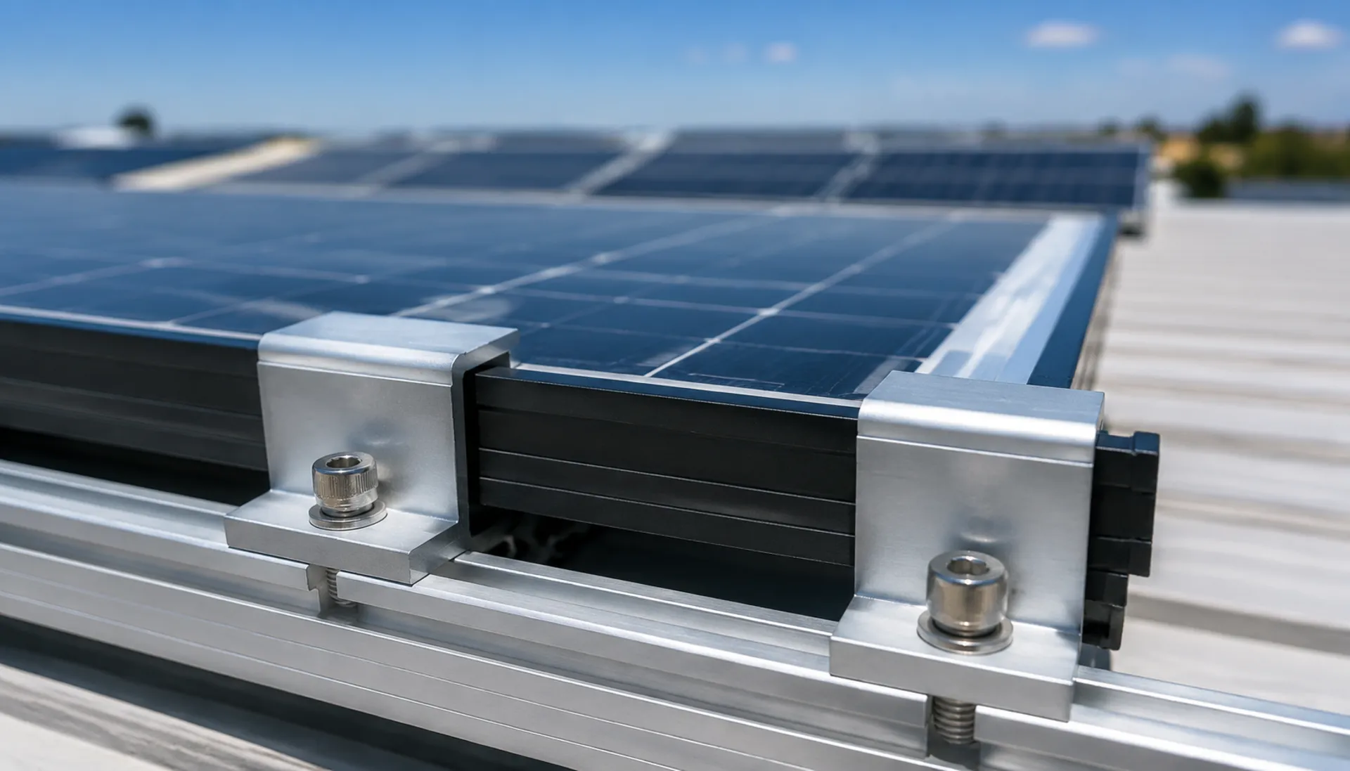
Roooftop Solar Clamps: Aluminum vs Stainless Steel
Selecting the right clamp material and type is critical for long-term reliability. Aluminum clamps offer lightweight design but degrade in coastal environments; stainless steel resists corrosion but adds roof load. Compare mid clamps and end clamps for module fixing, and understand risks like strength degradation, thermal deformation, and hidden cracks
RISK AUDIT // ENGINEERING DIAGNOSIS
Procurement Pitfall Avoidance Guide
"Field failures often trace back to material and installation oversights."
QC-AUDIT // REV.5
SCALE 1:1 · 03 ITEMS
RISK-01
Strength Degradation of Aluminum Clamps in Salt Spray Environments
Corrective Measures
RISK-02
Deformation Failure of Thin-Walled Clamps Under Module Thermal Expansion and Contraction
Corrective Measures
RISK-03
Lack of Cushion Pad Between Clamp and Module Frame Contact Surface Leads to Hidden Cracks
Corrective Measures
FIELD-SPECIFIC INSIGHT
Clamp Material & Design: Key Differences for Procurement
The choice between aluminum and stainless steel clamps affects not only corrosion resistance but also roof load, thermal expansion behavior, and long-term clamping force. Aluminum clamps (6063-T5) are lightweight but prone to pitting in C4-C5 environments; stainless steel (304/316) eliminates corrosion degradation but weighs 2. 8x more. Additionally, thin-walled clamps may deform under thermal cycling, and missing cushion pads can cause glass cracks
WHAT TO CHECK
- 1Aluminum 6063-T5 clamps: tensile strength ≥175MPa, anodized layer ≥15μm, suitable for C3 environments
- 2Stainless steel 304/316 clamps: tensile strength ≥500MPa, no corrosion degradation, required for C5 environments; weight ~2. 8x aluminum, must verify roof load capacity
- 3Thin-type clamps (40mm length) for 28-35mm frames: risk of plastic deformation after 10,000 thermal cycles (80°C range), reducing clamping force by >30%
- 4Cushion pads between clamp and module frame prevent point contact stress >50MPa and hidden glass cracks; specify in procurement
- 5Mid clamps fix module middles; end clamps fix array edges. Both must be used together to prevent module slippage
| Check | Why it matters | What to specify |
|---|---|---|
| Material & Corrosion Class | Aluminum anodized layer degrades in C4-C5; stainless steel resists but adds weight | Specify 6063-T5 + anodizing ≥15μm for C3; 304/316 stainless for C4-C5. Include ISO 12944-2 corrosion class |
| Clamp Length & Frame Compatibility | Wrong length causes poor fit or deformation under thermal cycling | Standard type: 50mm for 30-40mm frame; thin type: 40mm for 28-35mm frame. Verify frame thickness |
| Cushion Pad Requirement | Metal-to-metal contact leads to glass micro-cracks and power loss | Require EPDM or silicone cushion pad between clamp and frame. Specify pad hardness and thickness |
| Torque & Maintenance Schedule | Loose clamps reduce clamping force; over-torque damages frame | Specify torque value (e. G |
All performance data from page content. For specific torque values and load calculations, refer to project structural engineering
Evidence level: source-page-only
INDUSTRY TECH REFERENCE
How Galvanic Corrosion Eats an Aluminum Clamp Thin
Example: the common pairing of anodized aluminum clamps with 304 T-bolts. It is not the bolt that fails first — it is the aluminum.
- 1An aluminum clamp and a 304 stainless T-bolt share the same hole: aluminum is the anode, steel the cathode — a galvanic couple
- 2In humid coastal air (Cl⁻ deposition from ISO 9223 S2 upward demands galvanic protection), the aluminum dissolves faster
- 3The clamp's effective thickness at the loaded section keeps thinning, and clamping force drops with it
- 4With insufficient clamping force, the module starts to slide along the rail under wind vibration
- 5After enough slip, the module escapes the clamp's grip — the aluminum clamp fails before the module does
This chain carries no magnitude-estimate figures; the effective-thickness thinning → clamping-force loss follows the KB mechanism (§2.2 L30); S2 is the ISO 9223 Cl⁻ deposition boundary (KB §1 L18).
INDUSTRY TECH REFERENCE
Clamp Material by Environment: Anodized Aluminum vs Stainless Steel
Judge the environment before the material — coastal or not is the first line in clamp material selection.
| Environment | Clamp material | Matching spec |
|---|---|---|
| Inland, general environment (Cl⁻ deposition below ISO 9223 S2) | Anodized aluminum clamp (M8–M10) | Aluminum clamp with 304 bolt is the standard pairing; regular corrosion protection suffices |
| Coastal, humid environment (Cl⁻ deposition from ISO 9223 S2 upward) | 304 stainless clamp + EPDM insulating shim (≥1 mm) | Coastal hard requirement: 304 + EPDM insulation to break the galvanic couple |
S2 is the ISO 9223 Cl⁻ deposition boundary (KB §1 L18); coastal 304+EPDM is the KB procurement hard requirement (§4 L68); EPDM ≥1 mm follows the KB recommendation (§2.2 L32); M8–M10 sizes come from KB §5 L76.
PLAN COMPARISON
Three-Plan Core Parameter Comparison
Compare row by row. Click column headers to jump to plan details.
| A · ① Aluminum Mid Clamp | B · ② Aluminum End Clamp | C · ③ Stainless Steel Clamp (High Corrosion Environment) | |
|---|---|---|---|
| 1. ALUMINUM MID CLAMP (STANDARD TYPE) | |||
| SPEC | Length 50mm, suitable for 30-40mm frame | Length 50mm, suitable for 30-40mm frame | Length 50mm, suitable for 30-40mm frame |
| MATERIAL | 6063-T5 + Anodizing ≥15μm | 6063-T5 + Anodizing ≥15μm | 304 Stainless Steel (A2-70) |
| GRADE | AA15 | AA15 | A2-70 |
| FINISH | HDG >=55um per ISO 1461 | HDG >=55um per ISO 1461 | HDG >=55um per ISO 1461 |
| 2. ALUMINUM MID CLAMP (THIN TYPE) | |||
| SPEC | Length 40mm, suitable for 28-35mm frame | Length 40mm, suitable for 28-35mm frame | Length 50mm, suitable for 30-40mm frame |
| MATERIAL | 6063-T5 + Anodizing | 6063-T5 + Anodizing | 316 Stainless Steel (A4-80) |
| GRADE | AA10 | AA10 | A4-80 |
| FINISH | HDG >=55um per ISO 1461 | HDG >=55um per ISO 1461 | HDG >=55um per ISO 1461 |
| 3. MID CLAMP | |||
| SPEC | Length 50mm | Length 50mm | Length 50mm |
| MATERIAL | 304 Stainless Steel | 304 Stainless Steel | 304/316 Stainless Steel |
| GRADE | A2-70 | A2-70 | A2-70/A4-80 |
| FINISH | HDG >=55um per ISO 1461 | HDG >=55um per ISO 1461 | HDG >=55um per ISO 1461 |
SELECTION GUIDE
Selecting the Right Clamp for Your Rooftop Solar
| Operating condition | Recommended option | Key basis |
|---|---|---|
| Fixing the middle part of modules, suitable for all rooftop solar (C3) | Aluminum Mid Clamp (6063-T5, anodizing ≥15 μm / AA15) | C3 per ISO 12944-2 with anodizing ≥15 μm per AA15; standard type 50 mm for 30-40 mm frame, thin type 40 mm for 28-35 mm frame; lightweight with good corrosion resistance |
| Fixing modules at array edges | Aluminum End Clamp (6063-T5, anodizing ≥15 μm / AA15) | Must be used together with mid clamps to ensure modules do not slip; C4 harsh per ISO 12944-2; standard type 50 mm for 30-40 mm frame |
| Within 3 km of coast, around chemical plants, C4-C5 corrosion environments | Stainless Steel Clamp (304 A2-70 / 316 A4-80) | 304 recommended for C4 environments; 316 (A4-80) for C5/offshore; weighs ~2.8x aluminum so verify roof load; 50 mm length for 30-40 mm frame |
① Aluminum Mid Clamp
C3 (ISO 12944-2) with anodizing ≥15μm per AA15
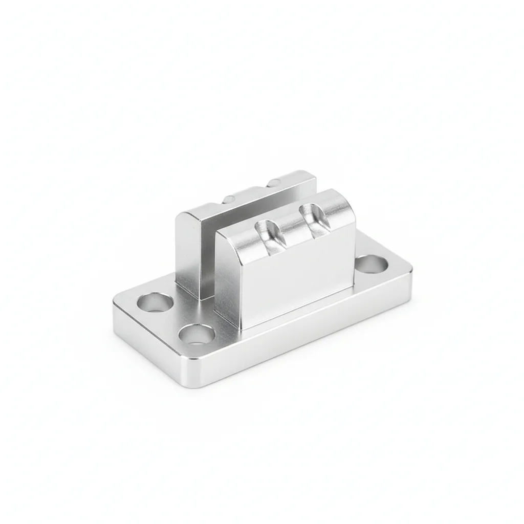
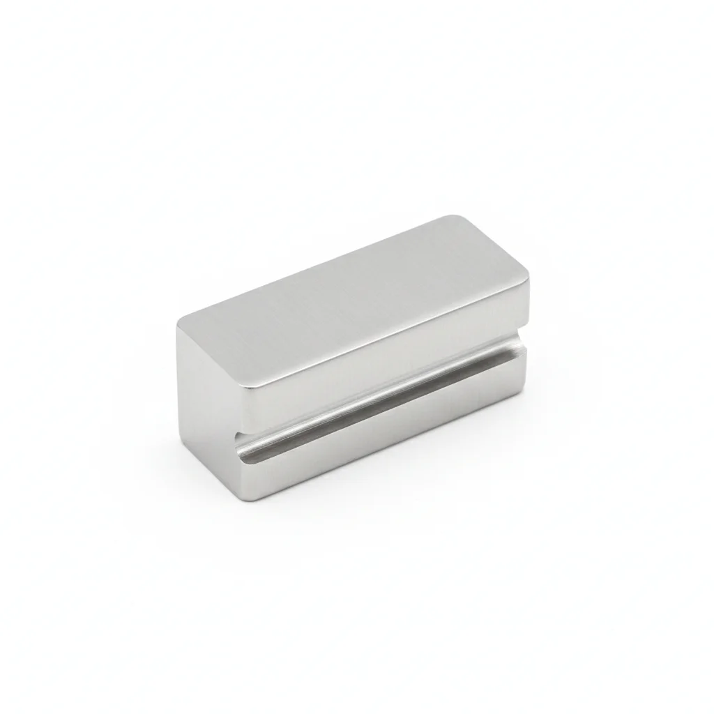
| Aluminum Mid Clamp (Standard Type) | Aluminum Mid Clamp (Thin Type) | Mid Clamp | |
|---|---|---|---|
| SPEC | Length 50mm, suitable for 30-40mm frame | Length 40mm, suitable for 28-35mm frame | Length 50mm |
| MATERIAL | 6063-T5 + Anodizing ≥15μm | 6063-T5 + Anodizing | 304 Stainless Steel |
| GRADE | AA15 | AA10 | A2-70 |
| FINISH | HDG >=55um per ISO 1461 | HDG >=55um per ISO 1461 | HDG >=55um per ISO 1461 |
| CORROSION | C3 (ISO 12944-2) | C3 (ISO 12944-2) | C3 (ISO 12944-2) |
| TEMP | -20°C to +80°C | -20°C to +80°C | -20°C to +80°C |
| WEIGHT | ~0.5 kg/piece | ~0.5 kg/piece | ~0.5 kg/piece |
| MOQ | 100 pcs | 100 pcs | 100 pcs |
| PACK | VCI paper + carton | VCI paper + carton | VCI paper + carton |
| STD | ISO 898-1, GB/T 3098.1 | ISO 898-1, GB/T 3098.1 | ISO 898-1, GB/T 3098.1 |
| USE | Standard module middle fixing | Dedicated for thin frame modules | Module fixing in coastal/high corrosion areas |
PROCEDURE
- Align the 50mm mid clamp over the 30-40mm frame joint, ensuring the EPDM cushion strip (2mm) sits flush between the clamp and frame to avoid metal-to-metal contact.
- Insert the M8 bolt through the clamp and rail, hand-tighten the nut, then torque to 12-15 N·m using a calibrated wrench to prevent glass stress and hidden cracks.
- Verify the clamp is centered on the frame and the gap between modules is uniform; adjust if needed to maintain alignment within the rail slot.
- For thin-type clamps (40mm, 28-35mm frames), confirm the frame sits fully in the clamp groove before final tightening.
- After torquing, inspect the EPDM pad for compression and ensure no bare aluminum touches the frame; record torque values in the QA log.
COMMON ERRORS
| ✕ WRONG | CONSEQUENCE | ✓ CORRECT |
|---|---|---|
| Overtightening the clamp bolt beyond the specified 12-15 N·m | Excessive stress on the glass edge creates micro-cracks, leading to a 3-8% power drop and potential module failure. | Use a calibrated torque wrench set to 12-15 N·m and verify with a torque audit on a sample. |
| Installing the clamp without the EPDM cushion pad | Metal-to-metal point contact stress exceeds 50MPa, causing glass micro-cracks and moisture ingress that degrades the seal. | Always use the integrated EPDM pad or add a 2mm EPDM strip before clamping. |
MAINTENANCE
Inspect clamps seasonally and after severe storms; check for EPDM pad wear, anodizing pitting (depth >0.3mm), and torque loss. Re-torque to 12-15 N·m if loose, and replace any clamp with visible corrosion or deformation.
② Aluminum End Clamp
C4 harsh per ISO 12944-2
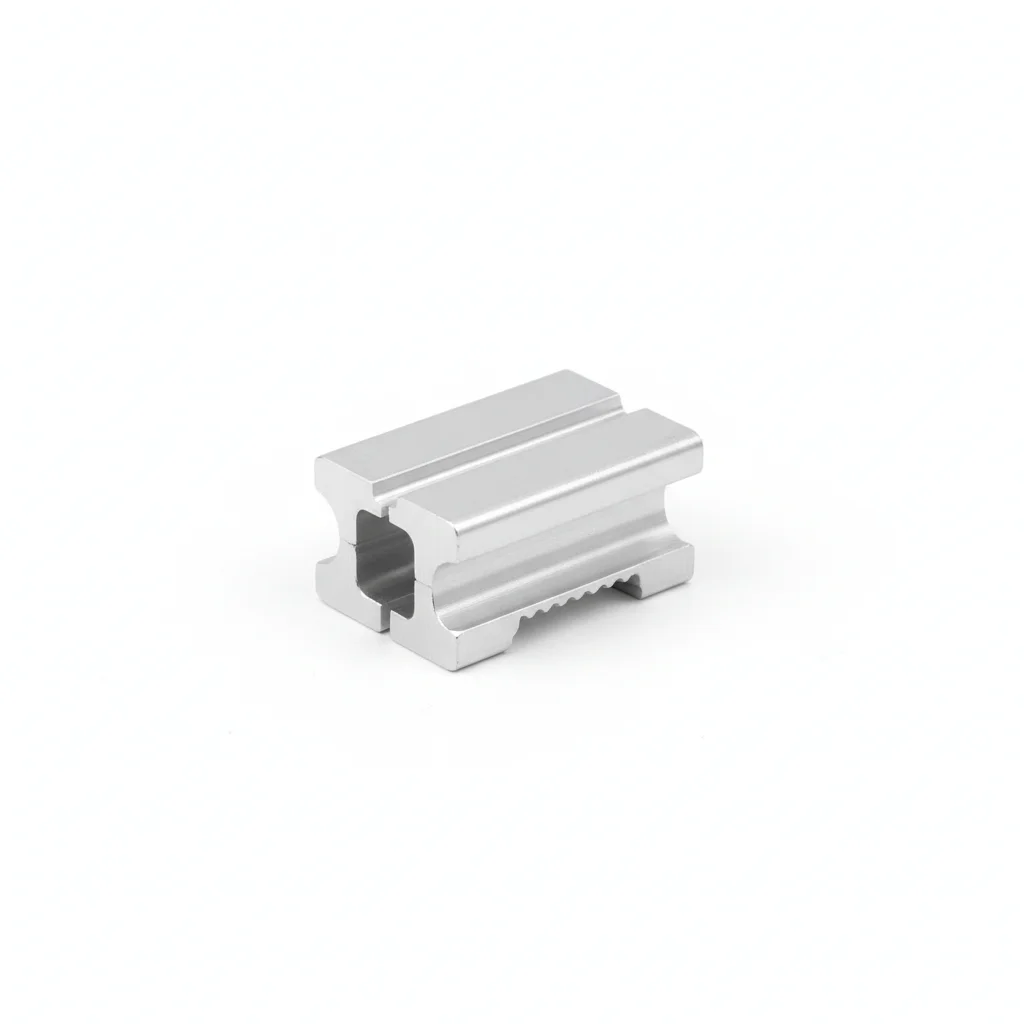
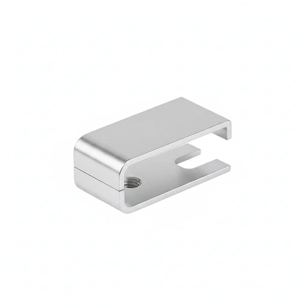
| Aluminum End Clamp | Aluminum End Clamp (Thin Type) | End Clamp | |
|---|---|---|---|
| SPEC | Length 50mm, suitable for 30-40mm frame | Length 40mm, suitable for 28-35mm frame | Length 50mm |
| MATERIAL | 6063-T5 + Anodizing ≥15μm | 6063-T5 + Anodizing | 304 Stainless Steel |
| GRADE | AA15 | AA10 | A2-70 |
| FINISH | HDG >=55um per ISO 1461 | HDG >=55um per ISO 1461 | HDG >=55um per ISO 1461 |
| CORROSION | C3 (ISO 12944-2) | C3 (ISO 12944-2) | C3 (ISO 12944-2) |
| TEMP | -20°C to +80°C | -20°C to +80°C | -20°C to +80°C |
| WEIGHT | ~0.5 kg/piece | ~0.5 kg/piece | ~0.5 kg/piece |
| MOQ | 100 pcs | 100 pcs | 100 pcs |
| PACK | VCI paper + carton | VCI paper + carton | VCI paper + carton |
| STD | ISO 898-1, GB/T 3098.1 | ISO 898-1, GB/T 3098.1 | ISO 898-1, GB/T 3098.1 |
| USE | Array edge module fixing | Thin frame module edge fixing | Edge fixing in coastal/high corrosion areas |
PROCEDURE
- Degrease the aluminum end clamp contact faces with acetone to remove any residual anodizing dust or handling oils.
- Fit the EPDM cushion strip (2mm) onto the clamp's module-facing surface to prevent metal-to-glass contact and accommodate frame thermal movement.
- Position the end clamp over the module edge and rail, aligning the 50mm length with the 30-40mm frame; hand-thread the M8 bolt to seat the clamp.
- Tighten in a cross-pattern sequence to the recommended torque for 6063-T5 aluminum (refer to project spec; avoid over-torque beyond 15 N·m to prevent frame deformation).
- Verify the clamp sits flush against the frame and that the module is held without vertical play; check that the anodized surface shows no scratches from installation tools.
- Apply a torque sealant mark on the bolt head and record the installation date and torque value in the QA log for future inspections.
COMMON ERRORS
| ✕ WRONG | CONSEQUENCE | ✓ CORRECT |
|---|---|---|
| Using an end clamp without the EPDM cushion on the glass edge of a thin-frame module. | Metal-to-glass contact creates point stress exceeding 50 MPa, leading to micro-cracks in the glass and a 3-8% power drop over thermal cycling. | Ensure the clamp is equipped with a 2mm EPDM cushion strip and verify it is positioned between the clamp and the module frame before final tightening. |
| Overtightening the M8 bolt on an aluminum end clamp beyond the specified torque range. | The 6063-T5 aluminum (≥175 MPa tensile) can yield at the thread or deform the clamp opening by 0.5-1mm, reducing clamping force by >30% after thermal cycles. | Use a calibrated torque wrench set to the recommended value (e.g., 12-15 N·m as per project spec) and avoid exceeding it; re-check torque after the first thermal cycle. |
MAINTENANCE
Inspect end clamps at each seasonal maintenance window (or per project schedule) for anodizing pitting or chalking, especially if within 3km of coast. Verify cushion pads are intact and not compressed beyond 50% of original thickness. Re-torque any clamp that has loosened below the specified value, but do not exceed the maximum torque to avoid frame damage. Replace any clamp showing visible corrosion or cracking, and document findings per ISO 12944-2 C4 guidelines.
③ Stainless Steel Clamp (High Corrosion Environment)
C5-M extreme per ISO 12944-2
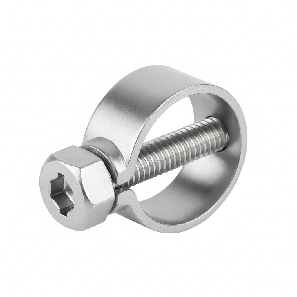
| Mid Clamp | Mid Clamp | End Clamp | |
|---|---|---|---|
| SPEC | Length 50mm, suitable for 30-40mm frame | Length 50mm, suitable for 30-40mm frame | Length 50mm |
| MATERIAL | 304 Stainless Steel (A2-70) | 316 Stainless Steel (A4-80) | 304/316 Stainless Steel |
| GRADE | A2-70 | A4-80 | A2-70/A4-80 |
| FINISH | HDG >=55um per ISO 1461 | HDG >=55um per ISO 1461 | HDG >=55um per ISO 1461 |
| CORROSION | C3 (ISO 12944-2) | C3 (ISO 12944-2) | C3 (ISO 12944-2) |
| TEMP | -20°C to +80°C | -20°C to +80°C | -20°C to +80°C |
| WEIGHT | ~0.5 kg/piece | ~0.5 kg/piece | ~0.5 kg/piece |
| MOQ | 100 pcs | 100 pcs | 100 pcs |
| PACK | VCI paper + carton | VCI paper + carton | VCI paper + carton |
| STD | ISO 898-1, GB/T 3098.1 | ISO 898-1, GB/T 3098.1 | ISO 898-1, GB/T 3098.1 |
| USE | Module middle fixing in C4 environment | Module fixing in C5/Offshore environment | Array edge fixing in high corrosion areas |
PROCEDURE
- Clean the stainless steel clamp and module frame contact areas with a solvent suitable for 304/316 surfaces to remove any salt deposits or contaminants.
- Install the 2mm EPDM cushion pad on the clamp's module-facing side to prevent galvanic corrosion between the stainless clamp and aluminum frame, and to damp vibration.
- Place the clamp over the module edge and rail, ensuring proper alignment; hand-thread the M8 bolt to secure the clamp without cross-threading.
- Tighten the bolt to the specified torque for stainless steel clamps (e.g., 15-20 N·m, but verify against project calculations; use anti-seize on threads to prevent galling).
- After installation, apply a protective sealant around the bolt head and clamp edges to block moisture ingress, as recommended for C5 environments.
- Verify the clamp is firmly seated and the module is held without movement; document the installation with photos for quality records.
COMMON ERRORS
| ✕ WRONG | CONSEQUENCE | ✓ CORRECT |
|---|---|---|
| Using an aluminum clamp in a C5 coastal environment without upgrading to stainless steel. | The anodized layer (≥15μm) pits within 3-5 years, reducing the effective cross-section by 10-20% and dropping strength from ≥175 MPa to ~140 MPa, risking clamp failure under wind load. | Select 304 (A2-70) or 316 (A4-80) stainless steel clamps for C5 areas; verify material grade via PMI testing if required. |
| Tightening a stainless steel bolt without a lubricant, causing galling and seizure. | Galling can strip threads or cause the bolt to break before achieving proper clamping force, leading to loose joints and module slippage. | Apply a suitable anti-seize compound (e.g., nickel-based) to the threads before installation, and use a calibrated torque wrench to achieve the specified torque without over-stressing the bolt. |
MAINTENANCE
Inspect stainless steel clamps at least seasonally for signs of pitting or rust staining, especially in marine environments. Check that the EPDM cushion pads remain intact and replace if cracked or compressed. Re-torque any loose clamps to the specified value, but do not exceed it. Apply a fresh coat of protective sealant if the original has degraded. Replace any clamp showing corrosion or cracking, and record all findings in the maintenance log.
REFERENCED STANDARDS
Technical Basis and Reference Standards
Design Standard for Photovoltaic Power Station
Photovoltaic System Testing ProceduresAluminum Alloy Building Profiles — Anodic Oxidation Coatings
Aluminum Alloy Building ProfilesDesign Specification for solar mounting structure
Photovoltaic Module Safety QualificationSUPPLIER CAPABILITY
Quality, Delivery & Customization
Quality Control
- ✓MTC material certificates with every batch
- ✓Key parts sampled for hardness/salt spray/torque coefficient
- ✓100% inspection or AQL sampling before shipment
Delivery
- ✓Standard parts made to order: 7-15 days
- ✓Custom parts: 25-45 days
- ✓FOB/CIF/DDP supported
Customization
- ✓Drawing review and material matching
- ✓Non-standard sizes/heads/threads
- ✓Small-batch prototyping supported
Certification
- ✓Material certificates (MTC)
- ✓Spectrographic analysis reports
- ✓Salt spray test reports (on request)
MOQ: No MOQ for standard parts; custom parts assessed by process complexity
FAQ
Frequently Asked Questions
RELATED READING
Keep Reading & Next Step
BEYOND TECHNICAL SPECS
Finding the right factory, controlling quality, delivering on time — that's the real challenge. We cover fasteners, rubber, plastics, industrial textiles. One team, end to end.
SEE CAPABILITIES →