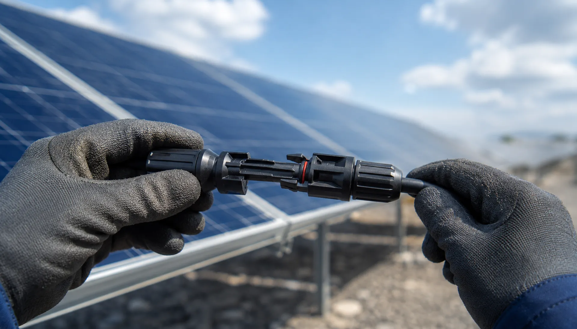
MC4 Connector Hot Spot Risk: Contact Resistance & Seal Aging in Solar DC Systems
MC4 connector contact resistance exceeding 0.5mΩ and seal aging after 5-8 years are the primary failure chain leading to hot spots and DC arc faults. This page explains the mechanism and provides procurement checkpoints for connectors, cables, and combiner box accessories
RISK AUDIT // ENGINEERING DIAGNOSIS
Procurement Pitfall Guide
"On the solar farm, the same connector failures repeat — here's what to inspect before you buy."
QC-AUDIT // REV.5
SCALE 1:1 · 03 ITEMS
RISK-01
MC4 Connector Contact Resistance Exceeding Limit Causes Hot Spots
Corrective Measures
RISK-02
MC4 Connector Seal Aging Leads to Increased Contact Resistance
Corrective Measures
RISK-03
Non-Uniform Combiner Box Terminal Specifications Increase On-Site Wiring Time
Corrective Measures
FIELD-SPECIFIC INSIGHT
MC4 Connector Failure Chain: What to Check Before Procurement
MC4 connector failures account for a significant share of PV system fires. The root cause is often poor crimping or seal aging, not the connector itself. Use this checklist to specify and verify critical parameters
WHAT TO CHECK
- 1Specify contact resistance <0.5mΩ per IEC 62852; verify with manufacturer test report
- 2Require UV-resistant housing material (PC/PA) and IP68 rating for seal longevity
- 3For enhanced type, confirm silver-plated contact and 40-70A rating for high-current strings
- 4For long-distance runs (>100m), select 6mm² cable to reduce voltage drop and heating
| Check | Why it matters | What to specify |
|---|---|---|
| Contact resistance | Exceeds 0.5mΩ → heating power rises 10x → housing aging → arc fault | Require <0.5mΩ per IEC 62852, include test report |
| Seal material & IP rating | Silicone hardens after 5-8 years → moisture ingress → corrosion → resistance increase | Silicone rubber seal, IP68 rated, UV-resistant housing |
| Crimping tool calibration | Uncalibrated pliers cause 70%+ of connector failures | Tool calibration certificate, crimp pull-out test per IEC 62852 |
| Cable cross-section | Undersized cable increases temperature and connector heating | 4mm² for ≤100m, 6mm² for >100m or high current |
Data based on IEC 62852 and industry failure statistics. Actual contact resistance may vary with installation quality
Evidence level: source-page-only
INDUSTRY TECH REFERENCE
How One Unlocked MC4 Climbs the Chain to a DC Arc
20-30 modules per string at 400-1500 V DC — leave one joint not fully home and the feedback loop accelerates on its own. The chain:
- 1An MC4 is pushed in but never clicks home — the contact faces are only half-seated
- 2Contact resistance stays high and the joint heats up under steady string current
- 3Heat feeds oxide growth and the growing oxide feeds heat — a runaway spiral
- 4The plastic housing melts and bares the copper core
- 5A DC arc strikes — with no zero crossing, a DC arc does not self-extinguish
The chain and the 20-30 modules per string (400-1500 V DC) follow verified failure mechanics; resistance and heating are qualitative, with no specific values given.
INDUSTRY TECH REFERENCE
Combiner Box and Inverter Base Bolts: Sizes, Torque and Re-Checks
A loose base bolt tips the enclosure first — and burns the connectors last. The comparison:
| Anchor point | Size | Material & locking | Torque rating | Failure path & re-check |
|---|---|---|---|---|
| Combiner box post fixing | M8-M12 | 304 + nylon-insert lock nut | — | Loosening → box tilts → busbar slack → overheating and burnout |
| Inverter base expansion bolt | M12 | Stainless expansion bolt | 50-60 N·m (not the 96-110 N·m for grade 8.8 steel) | Under-torque → vibration shifts the unit → cables get tugged → MC4 loosens → arc; annual IR scan, a hot spot above 10°C is abnormal (recommended) |
50-60 N·m is the stainless expansion-bolt product rating — grade 8.8 steel at the same size is 96-110 N·m; the annual IR scan with a >10°C hot-spot threshold is a recommended practice.
INDUSTRY TECH REFERENCE
MC4 and Cable Fixing Parts: Where the Fastener Scope Ends
Draw the buying line here, so complete assemblies are never quoted as fasteners.
The divide on this product line: combiner box/inverter base bolts, cable fixing clips and MC4 accessories stay in fastener scope; inverter/box assemblies, PV modules and aluminum rail profiles fall outside. Keep assemblies and modules out of fastener RFQs, while base bolts and connector accessories follow the fastener list.
The scope items are drawn from the procurement decision chain, limited to entries relevant to this product line.
PLAN COMPARISON
Three-Plan Core Parameter Comparison
Compare row by row. Click column headers to jump to plan details.
| A · ① MC4 PV Connector | B · ② PV1-F PV DC Cable | C · ③ DC Combiner Box Accessories | |
|---|---|---|---|
| 1. MC4 CONNECTOR (UNIVERSAL TYPE) | |||
| SPEC | 1500V DC / 30-50A | 56/0.285mm Tin-Plated Copper | 1000V/1500V DC 10-20A |
| MATERIAL | PC/PA Housing + Tin-Plated Copper Contact | Cross-linked Polyolefin Double Insulation | Ceramic Tube + Silver-Plated Contact |
| GRADE | IP68 | 1500V DC | gPV |
| FINISH | HDG >=55um per ISO 1461 | HDG >=55um per ISO 1461 | HDG >=55um per ISO 1461 |
| 2. MC4 CONNECTOR (ENHANCED TYPE) | |||
| SPEC | 1500V DC / 40-70A | 84/0.285mm Tin-Plated Copper | Voltage drop ≤0.8V |
| MATERIAL | PC/PA Housing + Silver-Plated Copper Contact | Cross-linked Polyolefin Double Insulation | Silicon Module |
| GRADE | IP68 | 1500V DC | — |
| FINISH | HDG >=55um per ISO 1461 | HDG >=55um per ISO 1461 | HDG >=55um per ISO 1461 |
| 3. MC4 BRANCH CONNECTOR | |||
| SPEC | 1-to-2 / 1-to-3 | Custom 0.5-10m | Type II Imax≥40kA Up≤3.8kV |
| MATERIAL | PC/PA + Tin-Plated Copper | PV1-F + MC4 Pre-assembled | MOV + Thermal Disconnector |
| GRADE | IP67 | 1500V DC | — |
| FINISH | HDG >=55um per ISO 1461 | HDG >=55um per ISO 1461 | HDG >=55um per ISO 1461 |
| 4. MC4 DUST CAP | |||
| SPEC | Fits MC4 | Fits 4-6mm² | Customized for combiner box |
| MATERIAL | PC/PA Rubber Seal | 304 Stainless Steel + EPDM | T2 Copper + Tin Plating |
| GRADE | IP68 | — | — |
| FINISH | HDG >=55um per ISO 1461 | HDG >=55um per ISO 1461 | HDG >=55um per ISO 1461 |
SELECTION GUIDE
Connector Selection Decision Aid
| Operating condition | Recommended option | Key basis |
|---|---|---|
| 1500V system; 1000V system may use universal type | Select a 1500V DC rated connector for 1500V systems, universal type for 1000V systems | IEC 62852 PV connector certification |
| Select by string maximum current | Calculate string max current as Isc×1.25, then size the fuse and cable cross-section | Fuse rated current 1.5× string max current (DC combiner box accessories) |
| Export project or domestic project | Choose TUV/UL certified products for export, GB certified products for domestic | TUV/UL and GB certification requirements |
① MC4 PV Connector
C3 per ISO 12944-2 with UV exposure
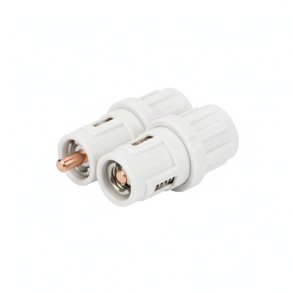
| MC4 Connector (Universal Type) | MC4 Connector (Enhanced Type) | MC4 Branch Connector | MC4 Dust Cap | |
|---|---|---|---|---|
| SPEC | 1500V DC / 30-50A | 1500V DC / 40-70A | 1-to-2 / 1-to-3 | Fits MC4 |
| MATERIAL | PC/PA Housing + Tin-Plated Copper Contact | PC/PA Housing + Silver-Plated Copper Contact | PC/PA + Tin-Plated Copper | PC/PA Rubber Seal |
| GRADE | IP68 | IP68 | IP67 | IP68 |
| FINISH | HDG >=55um per ISO 1461 | HDG >=55um per ISO 1461 | HDG >=55um per ISO 1461 | HDG >=55um per ISO 1461 |
| CORROSION | C3 (ISO 12944-2) | C3 (ISO 12944-2) | C3 (ISO 12944-2) | C3 (ISO 12944-2) |
| TEMP | -20°C to +80°C | -20°C to +80°C | -20°C to +80°C | -20°C to +80°C |
| WEIGHT | ~0.5 kg/piece | ~0.5 kg/piece | ~0.5 kg/piece | ~0.5 kg/piece |
| MOQ | 100 pcs | 100 pcs | 100 pcs | 100 pcs |
| PACK | VCI paper + carton | VCI paper + carton | VCI paper + carton | VCI paper + carton |
| STD | ISO 898-1, GB/T 3098.1 | ISO 898-1, GB/T 3098.1 | ISO 898-1, GB/T 3098.1 | ISO 898-1, GB/T 3098.1 |
| USE | 4mm²/6mm² PV1-F Cable | 6mm²/10mm² High Current | String Parallel Combining | Protection for Unused Ends |
PROCEDURE
- Strip 4mm²/6mm² PV1-F cable to the length specified by the connector datasheet, then slide the cable gland and seal over the jacket.
- Insert the stripped conductor into the crimp barrel and compress with the manufacturer-recommended crimping tool until the die closes fully.
- Verify the crimp by performing a pull test on a sample: for 4mm² cable, the pull-out force must be at least 310N.
- Mate the male and female housings until you hear the latch click, then hand-tighten the coupling nut to ensure the seal is compressed.
- For unused ports, attach the IP68 dust cap and hand-tighten to maintain the protection rating.
COMMON ERRORS
| ✕ WRONG | CONSEQUENCE | ✓ CORRECT |
|---|---|---|
| Using a generic crimping tool not specified by the MC4 manufacturer | Crimp force is insufficient, contact resistance can rise from <0.5mΩ to 5-10mΩ, generating heat that accelerates housing aging and can lead to arc faults. | Use the exact crimping tool model recommended by the connector manufacturer, and calibrate it every 2000 crimps. |
| Mixing connectors from different manufacturers in the same string | Pin diameter and latch geometry differ, leading to poor mating and a 10x increase in contact resistance, creating hot spots. | Keep all connectors from one brand and one series; verify compatibility before installation. |
MAINTENANCE
Perform infrared thermography at each overhaul window (seasonally or after extreme weather) and replace any connector whose temperature rise exceeds 10K. Batch-replace connectors after 10 years of service.
② PV1-F PV DC Cable
C3 (ISO 12944-2) with UV exposure and thermal cycling
| PV1-F Cable 4mm² | PV1-F Cable 6mm² | PV Extension Cable | Cable Fixing Clip | |
|---|---|---|---|---|
| SPEC | 56/0.285mm Tin-Plated Copper | 84/0.285mm Tin-Plated Copper | Custom 0.5-10m | Fits 4-6mm² |
| MATERIAL | Cross-linked Polyolefin Double Insulation | Cross-linked Polyolefin Double Insulation | PV1-F + MC4 Pre-assembled | 304 Stainless Steel + EPDM |
| GRADE | 1500V DC | 1500V DC | 1500V DC | — |
| FINISH | HDG >=55um per ISO 1461 | HDG >=55um per ISO 1461 | HDG >=55um per ISO 1461 | HDG >=55um per ISO 1461 |
| CORROSION | C3 (ISO 12944-2) | C3 (ISO 12944-2) | C3 (ISO 12944-2) | C3 (ISO 12944-2) |
| TEMP | -20°C to +80°C | -20°C to +80°C | -20°C to +80°C | -20°C to +80°C |
| WEIGHT | ~0.5 kg/piece | ~0.5 kg/piece | ~0.5 kg/piece | ~0.5 kg/piece |
| MOQ | 100 pcs | 100 pcs | 100 pcs | 100 pcs |
| PACK | VCI paper + carton | VCI paper + carton | VCI paper + carton | VCI paper + carton |
| STD | ISO 898-1, GB/T 3098.1 | ISO 898-1, GB/T 3098.1 | ISO 898-1, GB/T 3098.1 | ISO 898-1, GB/T 3098.1 |
| USE | String to Combiner Box (≤100m) | Long Distance Transmission or High Current | Connection between Module and Microinverter/Optimizer | Fixing cable on rail |
PROCEDURE
- Strip the cable sheath to the length specified for the MC4 connector, ensuring no nicked copper strands.
- Slide the cable gland and seal over the jacket before crimping the tin-plated copper contact.
- Use the manufacturer-recommended crimping tool with the correct die for 4mm² or 6mm² conductor.
- Perform a pull test on each crimp to verify the pull-out force meets the ≥310N requirement for 4mm² cable.
- Insert the crimped contact into the connector housing until the locking click is heard, then hand-tighten the coupling nut.
- Visually inspect the seal and housing for gaps or misalignment before final connection.
COMMON ERRORS
| ✕ WRONG | CONSEQUENCE | ✓ CORRECT |
|---|---|---|
| Using a universal crimping tool instead of the MC4-specific die | Insufficient crimp pressure raises contact resistance to 5-10mΩ, causing hot spots and potential arc faults. | Use the crimping tool specified by the connector manufacturer and calibrate it every 2000 crimps. |
| Mixing connectors from different manufacturers on the same string | Incompatible pin diameters or latch structures can increase contact resistance by 10 times, leading to overheating. | Keep all connectors within a string from the same brand and model; verify compatibility before installation. |
MAINTENANCE
Perform infrared thermography on all MC4 connections at each seasonal inspection; replace any connector showing a temperature rise over 10K above ambient. Check cable insulation resistance annually with a 1000V DC megohmmeter—new cable should read ≥100MΩ, and investigate if below 1MΩ.
③ DC Combiner Box Accessories
C3 (ISO 12944-2) indoor combiner box environment with DC arcing risk
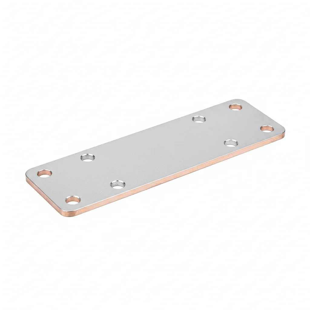
| DC Fuse | Blocking Diode | DC Surge Protective Device | Tin-Plated Copper Busbar | |
|---|---|---|---|---|
| SPEC | 1000V/1500V DC 10-20A | Voltage drop ≤0.8V | Type II Imax≥40kA Up≤3.8kV | Customized for combiner box |
| MATERIAL | Ceramic Tube + Silver-Plated Contact | Silicon Module | MOV + Thermal Disconnector | T2 Copper + Tin Plating |
| GRADE | gPV | — | — | — |
| FINISH | HDG >=55um per ISO 1461 | HDG >=55um per ISO 1461 | HDG >=55um per ISO 1461 | HDG >=55um per ISO 1461 |
| CORROSION | C3 (ISO 12944-2) | C3 (ISO 12944-2) | C3 (ISO 12944-2) | C3 (ISO 12944-2) |
| TEMP | -20°C to +80°C | -20°C to +80°C | -20°C to +80°C | -20°C to +80°C |
| WEIGHT | ~0.5 kg/piece | ~0.5 kg/piece | ~0.5 kg/piece | ~0.5 kg/piece |
| MOQ | 100 pcs | 100 pcs | 100 pcs | 100 pcs |
| PACK | VCI paper + carton | VCI paper + carton | VCI paper + carton | VCI paper + carton |
| STD | ISO 898-1, GB/T 3098.1 | ISO 898-1, GB/T 3098.1 | ISO 898-1, GB/T 3098.1 | ISO 898-1, GB/T 3098.1 |
| USE | Positive and negative protection for each string | Prevent reverse current flow to module | Lightning/ Switching overvoltage protection | Fuse installation and combining |
PROCEDURE
- Verify each fuse's rated current is 1.5 times the string's maximum current (Isc×1.25) before insertion.
- Mount the tin-plated copper busbar with proper spacing to allow heat dissipation and prevent arcing.
- Connect the blocking diode in series with the string's positive lead, observing polarity markings.
- Install the Type II surge protective device with the shortest possible grounding path to the combiner box earth bar.
- Torque all busbar and terminal connections to the value recommended by the busbar manufacturer, using a calibrated wrench.
- Label each fuse holder and SPD module with the string number for future identification and maintenance.
COMMON ERRORS
| ✕ WRONG | CONSEQUENCE | ✓ CORRECT |
|---|---|---|
| Selecting a fuse with a rating below the string's max current | The fuse may blow under normal operating conditions, causing unnecessary downtime and potential damage. | Calculate string max current as Isc×1.25 and choose a fuse rated at 1.5 times that value. |
| Overtightening the busbar connection without a torque wrench | Can strip threads or deform the busbar, increasing contact resistance and causing hot spots. | Use a calibrated torque wrench and follow the manufacturer's specified torque value for the busbar material. |
MAINTENANCE
At each overhaul window, inspect all fuse holders and busbar connections for signs of overheating (discoloration or melting). Test SPD modules for end-of-life indication and replace if the thermal disconnector has activated. Clean dust from the combiner box interior seasonally to prevent tracking.
REFERENCED STANDARDS
Technical Basis and Reference Standards
DC connectors for PV systems (MC4)
Design Qualification of PV TrackersCable standard for PV systems (PV1-F)
PV ConnectorsLow-voltage fuses — PV fuse-links
PV ConnectorsSurge protective devices for PV systems
GB/T 39750-2021Technical requirements for DC arc protection in PV power generation systems
SUPPLIER CAPABILITY
Quality, Delivery & Customization
Quality Control
- ✓MTC material certificates with every batch
- ✓Key parts sampled for hardness/salt spray/torque coefficient
- ✓100% inspection or AQL sampling before shipment
Delivery
- ✓Standard parts made to order: 7-15 days
- ✓Custom parts: 25-45 days
- ✓FOB/CIF/DDP supported
Customization
- ✓Drawing review and material matching
- ✓Non-standard sizes/heads/threads
- ✓Small-batch prototyping supported
Certification
- ✓Material certificates (MTC)
- ✓Spectrographic analysis reports
- ✓Salt spray test reports (on request)
MOQ: No MOQ for standard parts; custom parts assessed by process complexity
FAQ
Frequently Asked Questions
RELATED READING
Keep Reading & Next Step
BEYOND TECHNICAL SPECS
Finding the right factory, controlling quality, delivering on time — that's the real challenge. We cover fasteners, rubber, plastics, industrial textiles. One team, end to end.
SEE CAPABILITIES →