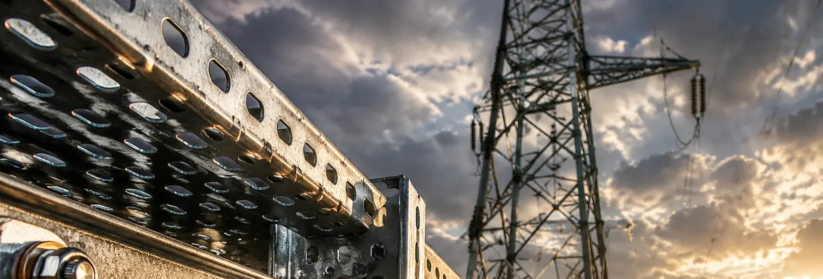
Cable Tray Hardware: Material & Coating Comparison for Substations
Cable trays rely on thousands of connectors and brackets. Choosing the wrong material risks corrosion perforation, eddy current heating, or loose joints. Compare hot-dip galvanized steel (C3), stainless steel/FRP (C4-C5), and aluminum alloy (non-magnetic) options with fastener grade and coating requirements
RISK AUDIT // ENGINEERING DIAGNOSIS
Procurement Pitfall Avoidance Guide
"In substation cable tray runs, the first failure is often a rusted bolt hole or a sagging span."
QC-AUDIT // REV.5
SCALE 1:1 · 03 ITEMS
RISK-01
Hot-dip Galvanized Steel Tray Corrosion Perforation in Coastal/Acid Rain Areas
Corrective Measures
RISK-02
Excessive Span Leading to Overload Sagging
Corrective Measures
RISK-03
Electromagnetic Eddy Current Heating in Cable Trays
Corrective Measures
FIELD-SPECIFIC INSIGHT
Connector & Bracket Corrosion: The Hidden Weak Point
While tray material gets attention, connector bolts and bracket fasteners often fail first due to coating damage at bolt holes. In coastal C4-C5 environments, hot-dip galvanized connectors may corrode within 5-8 years, while 316L stainless steel bolts (A4-80) maintain integrity. For single-core cables, steel brackets can cause eddy current heating; non-magnetic aluminum or FRP brackets eliminate this risk
WHAT TO CHECK
- 1Tray support connector bolts: Q235B hot-dip galvanized Grade 4.8 for C3 environments, 316L stainless steel A4-80 for C4-C5 environments, to prevent corrosion thinning from causing the tray to collapse.
- 2Single-core cables >200A in steel trays generate eddy currents: local temperature can exceed 80°C; use aluminum alloy or FRP trays and non-magnetic brackets
- 3Bracket span >2m increases sagging risk: deflection >1/200 of span causes cable sliding and sheath abrasion; verify load grade per IEC 61537
- 4Stainless steel bolts (A2-70) are adequate for C3, but in C5 or acid rain, upgrade to A4-80 for pitting resistance
| Check | Why it matters | What to specify |
|---|---|---|
| Connector bolt material vs environment | Coating damage at bolt holes accelerates corrosion; wrong grade leads to joint failure | For C3: HDG steel Grade 8.8; for C4-C5: 316L A4-80; for non-magnetic: aluminum alloy or FRP |
| Tray material for single-core cables | Steel trays cause eddy current heating and power loss | C3: Q235B hot-dip galvanized Grade 4.8; C4-C5: 316L A4-80 |
| Bracket span and load rating | Excessive span causes sagging and cable damage | Span ≤2m; load grade per IEC 61537 (A=7. 5kg/m, D=37. 5kg/m); verify actual cable weight |
| Cover plate clip fixing | Loose clips cause cover vibration and dust ingress | 304 stainless steel snap clips; check retention force per manufacturer spec |
All fastener torque values and inspection intervals should be verified against project specifications. No standard torque values are provided here as they depend on bolt size and grade
Evidence level: source-page-only
INDUSTRY TECH REFERENCE
Cable Tray Load Grades: What Each Tier Carries
Pick the tray load grade by the actual total weight per meter of cables and fittings — when it exceeds a tier, move up one.
| Grade | Safe working load |
|---|---|
| A | 0.5 kN/m |
| AA | 1.0 kN/m |
| B | 1.5 kN/m |
| C | 2.0 kN/m |
| D | 2.5 kN/m |
Grades follow Table 12 of GB/T 21762-2008 (safe working load grades, verified); the legacy 7.5/15/30/37.5 kg/m basis (≈7× off) has been corrected — do not reuse it.
INDUSTRY TECH REFERENCE
Tray Bracket Hardware: Sizes, Coating, and Anti-Corrosion Basis
Bracket and splice bolts are the tray system's hidden hardware — source and accept them on this basis.
- Sizes M8–M12 in hot-dip galvanized steel or 304 — tray and joint hardware coating per GB/T 13912 tiers (from ≥70 μm; the legacy 65 μm basis has been corrected)
- Inland C3: hot-dip galvanized bracket bolts suffice; C4–C5 (coastal/acid rain): ≥70 μm coating, Dacromet, or 316L — any one of the three meets the protective basis
- Coating tiers 55/70/85 μm — verify against the tier on delivery; a composition report alone is not enough, reject the batch when the tier falls short
- Bracket bolts are project-order, high-volume parts — require same-batch supply with coating test reports to keep batch consistency
Figures follow the KB-verified basis (M8–M12 per §5; tiers from ≥70 μm per §2.2.1; 55/70/85 μm per §6.5); the C4–C5 options are protective-coating choices — pick one.
INDUSTRY TECH REFERENCE
When Steel Trays Must Give Way to Another Material
Hit any of these three boundary conditions and ordinary steel trays are out.
R≥10 mm is a suggested value (corona control); 6063-T5/FRP/304 and the C3–C5 classes are KB material/anti-corrosion basis; the eddy-current mechanism is qualitative (no metric figures here).
PLAN COMPARISON
Three-Plan Core Parameter Comparison
Compare row by row. Click column headers to jump to plan details.
| A · Plan A · Hot-dip Galvanized Steel Tray Standard Plan | B · Plan B · Stainless Steel/FRP Anti-corrosion Enhanced | C · Plan C · Aluminum Alloy/Non-magnetic Plan | |
|---|---|---|---|
| 1. LADDER CABLE TRAY | |||
| SPEC | Width 200-800mm, rung spacing 225mm, internal depth ≥75mm (hot-dip galvanized as a complete assembly after fabrication) | Width 200-800mm | Width 200-800mm |
| MATERIAL | Hot-dip Galvanized Steel ≥65μm | Glass Fiber Reinforced Plastic | 6063-T5 Aluminum Alloy |
| GRADE | IEC 61537 | Flame Retardant V0, Salt Spray Resistant 3000h | Anodized |
| FINISH | HDG >=55um per ISO 1461 | HDG >=55um per ISO 1461 | HDG >=55um per ISO 1461 |
| 2. PERFORATED CABLE TRAY | |||
| SPEC | Width 200-600mm | Width 200-600mm | Custom |
| MATERIAL | Hot-dip Galvanized Steel ≥65μm | 304 Stainless Steel | FRP/Aluminum Alloy |
| GRADE | IEC 61537 | A2-70 | Insulating |
| FINISH | HDG >=55um per ISO 1461 | HDG >=55um per ISO 1461 | HDG >=55um per ISO 1461 |
| 3. CABLE TRAY BRACKET CONNECTOR | |||
| SPEC | M8-M12 | M8-M12 | M10-M12 |
| MATERIAL | Q235B Hot-dip Galvanized | 316L Stainless Steel | 304 Stainless |
| GRADE | Grade 4.8 | A4-80 | A2 |
| FINISH | HDG >=55um per ISO 1461 | HDG >=55um per ISO 1461 | Passivated |
| 4. COVER PLATE SNAP CLIP | |||
| SPEC | Fits Tray Width | M10-M12 | M10-M12 |
| MATERIAL | 304 Stainless Steel | 304 Stainless | 304 Stainless |
| GRADE | A2-70 | A2 | A2 |
| FINISH | HDG >=55um per ISO 1461 | Passivated | Passivated |
Plan A · Hot-dip Galvanized Steel Tray Standard Plan
Plan A hot-dip galvanized steel cable trays suit C3 inland environments: trays and connectors in hot-dip galvanized steel (coating ≥65μm), bolts Q235B hot-dip galvanized Grade 4.8, design service life 15-20 years (tray) / 25 years (hot-dip galvanized + anti-corrosion paint), executed to IEC 61537.
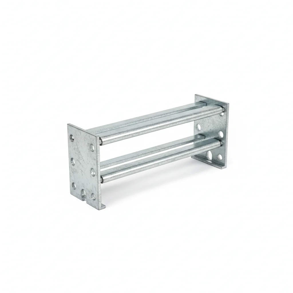
| Ladder Cable Tray | Perforated Cable Tray | Cable Tray Bracket Connector | Cover Plate Snap Clip | |
|---|---|---|---|---|
| SPEC | Width 200-800mm, rung spacing 225mm, internal depth ≥75mm (hot-dip galvanized as a complete assembly after fabrication) | Width 200-600mm | M8-M12 | Fits Tray Width |
| MATERIAL | Hot-dip Galvanized Steel ≥65μm | Hot-dip Galvanized Steel ≥65μm | Q235B Hot-dip Galvanized | 304 Stainless Steel |
| GRADE | IEC 61537 | IEC 61537 | Grade 4.8 | A2-70 |
| FINISH | HDG >=55um per ISO 1461 | HDG >=55um per ISO 1461 | HDG >=55um per ISO 1461 | HDG >=55um per ISO 1461 |
| CORROSION | C3 (ISO 12944-2) | C3 (ISO 12944-2) | C3 (ISO 12944-2) | C3 (ISO 12944-2) |
| TEMP | -20°C to +80°C | -20°C to +80°C | -20°C to +80°C | -20°C to +80°C |
| WEIGHT | ~0.5 kg/piece | ~0.5 kg/piece | ~0.5 kg/piece | ~0.5 kg/piece |
| MOQ | 100 pcs | 100 pcs | 100 pcs | 100 pcs |
| PACK | VCI paper + carton | VCI paper + carton | VCI paper + carton | VCI paper + carton |
| STD | ISO 898-1, GB/T 3098.1 | ISO 898-1, GB/T 3098.1 | ISO 898-1, GB/T 3098.1 | ISO 898-1, GB/T 3098.1 |
| USE | Power Cable Main Routing | Control Cable/Signal Cable | Tray Installation and Splicing | Tray Cover Plate Fixing |
PROCEDURE
- Lay out the hot-dip galvanized steel tray sections (width 200-800mm) along the planned route, confirming bracket spacing adheres to the 1.5-2.0m standard for C3 inland substations.
- Align tray flanges and insert M8-M12 Grade 8.8 hot-dip galvanized bolts through the splice holes, ensuring the zinc coating around the bolt holes remains intact to avoid premature corrosion.
- When joining tray sections, fasten the connecting plate to the tray body with M8-M12 hot-dip galvanized bolts (Grade 4.8), bolt heads facing outward, with flat washers and spring washers on the nut side to prevent loosening.
- Secure cover plates with 304 stainless steel snap clips (A2-70) at every tray section, checking that clips engage fully to prevent vibration and dust ingress.
- After installation, apply an additional epoxy coal tar anti-corrosion paint layer (thickness ≥200μm) to all bolt heads and cut edges where the galvanized coating may have been damaged.
COMMON ERRORS
| ✕ WRONG | CONSEQUENCE | ✓ CORRECT |
|---|---|---|
| Using plain Q235B bolts instead of hot-dip galvanized Grade 4.8 bolts, or a zinc coating thickness below 65μm. | Rust initiates at the bolt holes, spreading to the tray body and reducing structural strength within 5-8 years in C3 environments. | Use Q235B hot-dip galvanized bolts, coating thickness ≥65μm, Grade 4.8, and check the coating integrity. |
| Overtightening M8-M12 bolts beyond the grade 8.8 proof load | Bolt yield or thread stripping causes loose joints, leading to tray misalignment and cable sheath abrasion. | Tighten bolts with a calibrated torque wrench to the manufacturer's specified torque for grade 8.8 fasteners, verifying with a torque audit on a 5% sample. |
MAINTENANCE
Inspect tray joints and bolt coatings seasonally and after any severe weather; re-torque any loose connectors immediately. Replace fasteners showing rust or zinc loss exceeding 5% of surface area, and reapply anti-corrosion paint to any damaged areas. At each overhaul window, perform a full load test to verify deflection remains below 1/300 of span.
Plan B · Stainless Steel/FRP Anti-corrosion Enhanced
C4 Harsh per ISO 12944-2
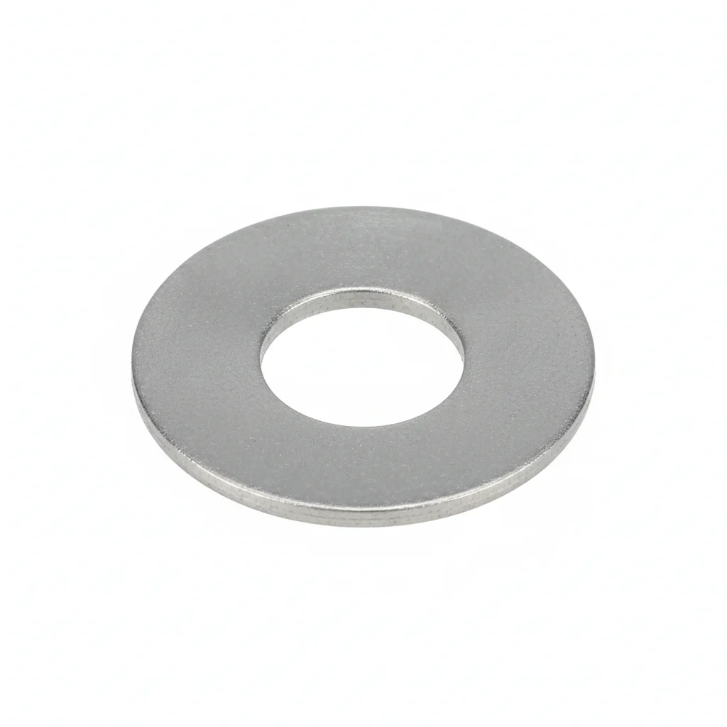
| FRP Ladder Tray | Perforated Tray | Connector Bolt | Flat Washer | |
|---|---|---|---|---|
| SPEC | Width 200-800mm | Width 200-600mm | M8-M12 | M10-M12 |
| MATERIAL | Glass Fiber Reinforced Plastic | 304 Stainless Steel | 316L Stainless Steel | 304 Stainless |
| GRADE | Flame Retardant V0, Salt Spray Resistant 3000h | A2-70 | A4-80 | A2 |
| FINISH | HDG >=55um per ISO 1461 | HDG >=55um per ISO 1461 | HDG >=55um per ISO 1461 | Passivated |
| CORROSION | C3 (ISO 12944-2) | C3 (ISO 12944-2) | C3 (ISO 12944-2) | C3 (ISO 12944-2) |
| TEMP | -20°C to +80°C | -20°C to +80°C | -20°C to +80°C | -20°C to +80°C |
| WEIGHT | ~0.5 kg/piece | ~0.5 kg/piece | ~0.5 kg/piece | ~0.005kg |
| MOQ | 100 pcs | 100 pcs | 100 pcs | 500 pcs |
| PACK | VCI paper + carton | VCI paper + carton | VCI paper + carton | Plastic bag |
| STD | ISO 898-1, GB/T 3098.1 | ISO 898-1, GB/T 3098.1 | ISO 898-1, GB/T 3098.1 | ISO 7089 |
| USE | C5 Corrosion Zone Cable Laying | Coastal Substation | FRP/Stainless Steel Tray Connection | Load distribution |
PROCEDURE
- Degrease all mating surfaces with acetone to remove any salt or acid residues typical of coastal exposure, then verify surface roughness Ra <3.2um.
- Apply a corrosion-inhibiting joint compound compatible with FRP and 304/316L stainless steel, and use PTFE-coated washers under bolt heads and nuts to prevent crevice corrosion.
- Align tray sections and connectors within 0.5mm, then tighten M8-M12 A4-80 bolts in a cross-pattern sequence; check 10% of fasteners with a verification torque tool and record environmental conditions.
- Conduct a pull-test on a 5% random sample of connections to 80% of proof load, replacing any that do not meet the acceptance threshold.
- After installation, apply a weatherproof protective coating to all exposed threads and install corrosion monitoring coupons near critical joints to track chloride ingress.
COMMON ERRORS
| ✕ WRONG | CONSEQUENCE | ✓ CORRECT |
|---|---|---|
| Mixing 304 stainless bolts with FRP trays and using uncoated carbon steel washers | Galvanic corrosion between the carbon steel washer and stainless bolt accelerates in salt-laden air, leading to washer failure and loose joints within months. | Use only A4-80 (316L) bolts and 304 stainless or PTFE-coated washers throughout the FRP/stainless assembly to ensure material compatibility. |
| Overtightening bolts on FRP trays, causing crushing or cracking of the composite material around bolt holes | Localized stress concentrations lead to micro-cracks that propagate under vibration, reducing tray load capacity and potentially causing sudden failure. | Follow the manufacturer's torque specification for FRP—typically lower than for steel—and use large-area washers to distribute load; verify with a torque wrench. |
MAINTENANCE
Inspect all fasteners and tray surfaces seasonally, and after any severe storm or salt fog event. Re-torque any bolt that has lost more than 20% of its initial specified torque. Replace any fastener showing rust staining, pitting deeper than 0.3mm, or affecting more than 5% of surface area. At each major overhaul window, disassemble a 20% sample of connections to check for hidden crevice corrosion, and replace all critical fasteners every 5 years regardless of apparent condition.
Plan C · Aluminum Alloy/Non-magnetic Plan
C5-M Extreme per ISO 12944-2
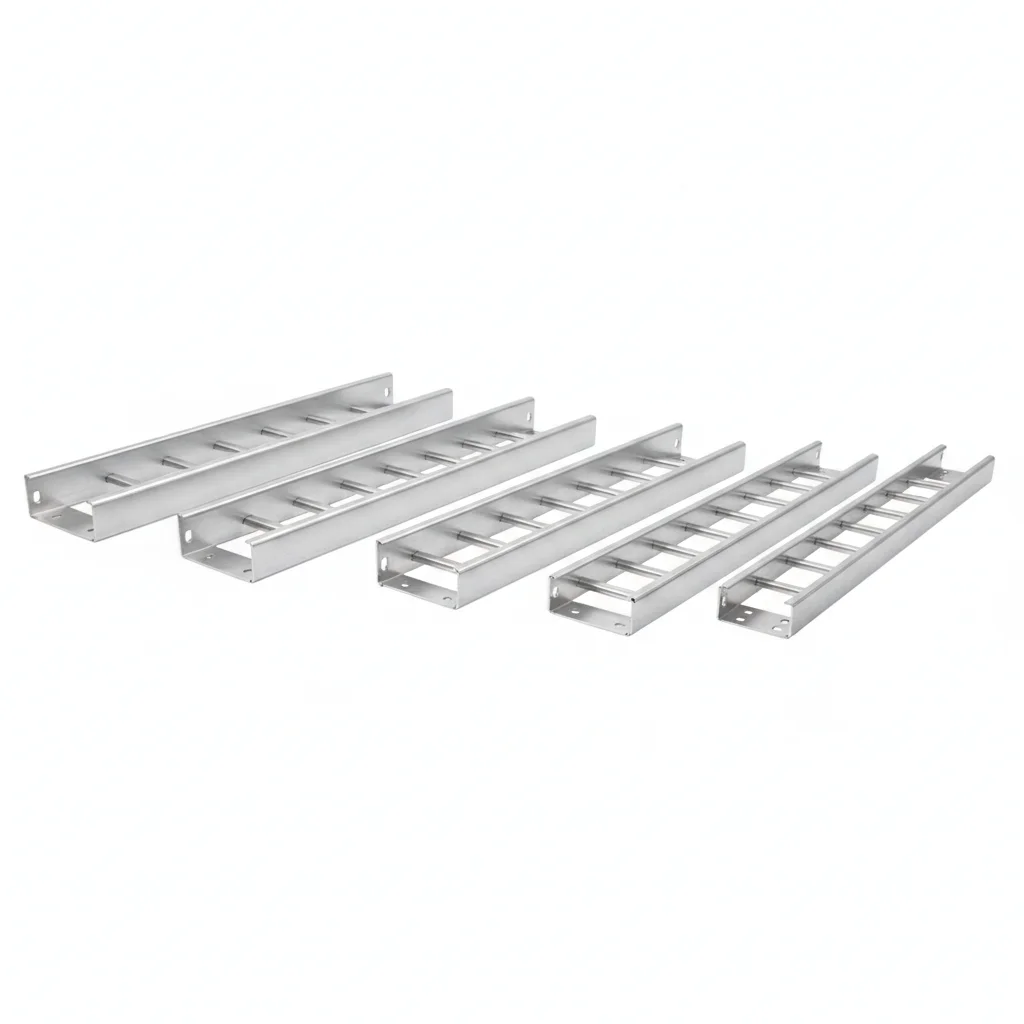
| Aluminum Alloy Ladder Tray | Non-magnetic Partition | Flat Washer | Flat Washer | |
|---|---|---|---|---|
| SPEC | Width 200-800mm | Custom | M10-M12 | M10-M12 |
| MATERIAL | 6063-T5 Aluminum Alloy | FRP/Aluminum Alloy | 304 Stainless | 304 Stainless |
| GRADE | Anodized | Insulating | A2 | A2 |
| FINISH | HDG >=55um per ISO 1461 | HDG >=55um per ISO 1461 | Passivated | Passivated |
| CORROSION | C3 (ISO 12944-2) | C3 (ISO 12944-2) | C3 (ISO 12944-2) | C3 (ISO 12944-2) |
| TEMP | -20°C to +80°C | -20°C to +80°C | -20°C to +80°C | -20°C to +80°C |
| WEIGHT | ~0.5 kg/piece | ~0.5 kg/piece | ~0.005kg | ~0.005kg |
| MOQ | 100 pcs | 100 pcs | 500 pcs | 500 pcs |
| PACK | VCI paper + carton | VCI paper + carton | Plastic bag | Plastic bag |
| STD | ISO 898-1, GB/T 3098.1 | ISO 898-1, GB/T 3098.1 | ISO 7089 | ISO 7089 |
| USE | Single-core Cable Eddy Current Elimination | Three-phase Cable Grouping and Separation | Load distribution | Load distribution |
PROCEDURE
- Clean all aluminum and FRP surfaces with MEK to remove any oily residues, and verify surface roughness Ra <1.6um to ensure proper bonding of protective compounds.
- Apply a marine-grade anti-corrosion compound rated for extreme temperatures and use PTFE-encapsulated washers to prevent galvanic corrosion between aluminum and stainless fasteners.
- Position non-magnetic partitions to separate three-phase cables in trefoil formation, then align tray sections within 0.3mm. Tighten bolts using a hydraulic tensioner to achieve precise preload, and verify material grade of 10% of fasteners by PMI testing.
- Perform NDT dye penetrant testing on 10% of welded or high-stress connections, replacing any that show crack indications.
- Apply a protective sealant to all exposed fastener heads and joints, and install permanent condition monitoring sensors to track temperature rise and vibration from eddy currents.
COMMON ERRORS
| ✕ WRONG | CONSEQUENCE | ✓ CORRECT |
|---|---|---|
| Using steel bolts or brackets on aluminum trays without isolation | Galvanic corrosion rapidly degrades the aluminum around bolt holes, and steel brackets cause eddy current heating that can raise local temperatures above 80°C, damaging cable insulation. | Use non-magnetic aluminum or FRP brackets and stainless steel bolts with insulating washers or coatings to prevent bimetallic corrosion and eliminate eddy currents. |
| Laying single-core cables without grouping phases in trefoil formation | Unbalanced magnetic flux induces eddy currents in nearby metal parts, causing overheating, power loss, and vibration that loosens fasteners and abrades cable sheaths. | Group A/B/C phases together and use non-magnetic partitions to maintain trefoil arrangement, ensuring the net magnetic field is near zero. |
MAINTENANCE
Inspect all fasteners and tray components seasonally, and after any event that could cause overheating (e.g., high load periods). Monitor temperature rise at joints; if any point exceeds the rated 80°C threshold, investigate immediately. Re-torque any bolt that has lost more than 15% of specified preload. Replace any aluminum component showing pitting or corrosion. At each major overhaul, perform a full inspection of all connections, and replace critical fasteners every 5 years to prevent fatigue in high-vibration environments.
SELECTION GUIDE
Which Plan Fits Your Site?
| Operating condition | Recommended option | Key basis |
|---|---|---|
| Inland general, C3 environment | Plan A: Hot-dip galvanized steel trays (coating ≥65μm) with Q235B hot-dip galvanized Grade 4.8 bolts | IEC 61537 |
| Coastal / acid rain C4-C5 | Plan B: FRP trays (flame retardant V0, salt spray resistant 3000h) or 304 stainless steel trays with 316L A4-80 connector bolts | IEC 61537 |
| Single-core high current / high EMC requirements | Plan C: 6063-T5 anodized aluminum alloy trays + non-magnetic FRP/aluminum partitions for phase grouping | IEC 61537 |
| Bracket span and load rating | Standard bracket spacing 1.5-2.0m, tightened to 1.0-1.2m for large cross-section cables; safety factor 1.5; deflection <1/300 of span after 24h full load | IEC 61537 |
| Single-core cables in steel trays (eddy current) | Group A/B/C phases in trefoil formation with non-magnetic partitions, or use non-magnetic aluminum/FRP trays to eliminate eddy currents | IEC 61537 |
REFERENCED STANDARDS
Referenced Standards
SUPPLIER CAPABILITY
Quality, Delivery & Customization
Quality Control
- ✓MTC material certificates with every batch
- ✓Key parts sampled for hardness/salt spray/torque coefficient
- ✓100% inspection or AQL sampling before shipment
Delivery
- ✓Standard parts made to order: 7-15 days
- ✓Custom parts: 25-45 days
- ✓FOB/CIF/DDP supported
Customization
- ✓Drawing review and material matching
- ✓Non-standard sizes/heads/threads
- ✓Small-batch prototyping supported
Certification
- ✓Material certificates (MTC)
- ✓Spectrographic analysis reports
- ✓Salt spray test reports (on request)
MOQ: No MOQ for standard parts; custom parts assessed by process complexity
FAQ
FAQ
RELATED READING
Keep Reading & Next Step
NEXT: SELECTION & RFQ
Busbar FittingsFollow this page's selection path to the same-scenario RFQ page.
RELATED TOPIC
Incoming Inspection of Power Transmission Fasteners: An Experienced Worker's Checklist, Don't Skip ItBEYOND TECHNICAL SPECS
Finding the right factory, controlling quality, delivering on time — that's the real challenge. We cover fasteners, rubber, plastics, industrial textiles. One team, end to end.
SEE CAPABILITIES →