
Insulator Hardware: Steel Pin & Cap Material Comparison for Pollution Zones
Insulator hardware—steel pins, caps, cotter pins, bases—are the hidden skeleton of insulator strings. In polluted or coastal environments, corrosion at the porcelain-steel interface can cause sudden pin fracture and conductor drop. This page compares standard HDG, 316 stainless, and Dacromet-coated options to help you select the right material for your pollution class
RISK AUDIT // ENGINEERING DIAGNOSIS
Procurement Pitfall Guide
"Corrosion and loosening failures start at the steel-porcelain interface, not on the visible insulator body."
QC-AUDIT // REV.5
SCALE 1:1 · 03 ITEMS
RISK-01
Corrosion and Fracture of Insulator Steel Pins in Polluted Environments
Corrective Measures
RISK-02
Loosening of Post Insulator Base Bolts Under Wind Vibration
Corrective Measures
RISK-03
Pin Insulator Cotter Pin Withdrawal Causing Conductor Disconnection
Corrective Measures
FIELD-SPECIFIC INSIGHT
3 Critical Checks for Insulator Hardware Procurement
Insulator hardware failures often originate at the steel-porcelain interface, not in the visible insulator body. The table below highlights the most overlooked differences between standard and reinforced hardware for pollution zones
WHAT TO CHECK
- 1Steel pin material: Q345B HDG (C3) vs 316 stainless (C4) vs 42CrMo + Dacromet (C5-M) — each has different corrosion resistance and mechanical strength
- 2Specify ≥85μm or upgrade to stainless
- 3Cotter pin retention: In wind-vibration zones, standard split pins can withdraw; use Dacromet-coated or stainless cotter pins with positive locking
| Check | Why it matters | What to specify |
|---|---|---|
| Pollution class (ISO 12944-2) | Determines minimum corrosion protection for steel pins and caps | C3 for inland general, C4 for coastal/industrial, C5-M for offshore |
| Steel pin material & coating | Corrosion at porcelain-steel interface reduces pin cross-section, leading to sudden fracture | 316 stainless or 42CrMo + Dacromet for C4+ |
| Cotter pin locking method | Wind vibration can cause pin withdrawal, leading to conductor slip | Use split pins with positive locking or Dacromet-coated pins for heavy vibration areas |
All material and coating selections should be verified against project-specific pollution class and expected service life. No single material suits all environments
Evidence level: source-page-only
INDUSTRY TECH REFERENCE
Insulator vs Fitting Standards: Get the Mapping Right
One word apart in the name, completely different scope — map them before you source.
Standard list for cross-checking; apply the version in force for the project.
INDUSTRY TECH REFERENCE
Insulator String Hardware: Four Acceptance Points
Where the porcelain looks fine is exactly where the hardware fails first.
- Ball-and-socket joints: tensile ≥60 kN (magnitude estimate) — sample tensile-test by grade
- Cotter pins must seat fully — anti-withdrawal is the first defense against string drop in wind vibration
- 500 kV and above must carry grading rings
- Coastal/heavy pollution (C4-C5): upgrade materials — HDG ≥70 μm, Dacromet, or 316L
≥60 kN is a magnitude estimate; ≥70 μm is the C4-C5 HDG corrosion-protection figure (KB §2.2.3).
INDUSTRY TECH REFERENCE
Zinc-Coated Steel Pins in Acid Rain: A 25-Year Design Life Shrinks
Example: galvanized steel pins of outdoor insulator strings in an acid-rain zone (pH<5).
- 1In acid rain with pH<5, zinc consumption runs 3-5× the inland rate (magnitude estimate)
- 2A 25-year design coating penetrates in about 10-12 years — consistent with ISO 9223 C5 rates (4.2-8.4 μm/yr) and 50-100 μm coatings (magnitude estimate)
- 3After threading, the thread zinc layer is only 60-70% of the shank (magnitude estimate) — threads and the porcelain-pin interface corrode first
- 4Once the zinc is through, the bare steel loses section year by year and fractures with no warning — in acid rain/coastal zones upgrade straight to C5: Dacromet or 316L
All figures in this slot are magnitude estimates (incl. the ISO 9223-consistent projection); upgrade materials per §2.2.3 (C4-C5: HDG ≥70 μm / Dacromet / 316L).
INDUSTRY TECH REFERENCE
Know the Boundary: What's In and What's Out
Before sourcing insulator hardware, confirm the order sits inside the supply boundary.
In scope: standard string hardware such as ball-and-socket joints, pins, and ball-head links, supplied to GB/T 2314. Out of scope: fasteners inside 500 kV+ GIS (SF6-sealed interfaces) and OPGW splice hardware are not routine supply — confirm the boundary at tender time, and do not buy sealing parts as ordinary bolts.
Boundary per the KB procurement decision-chain in/out scope.
PLAN COMPARISON
Three-Plan Core Parameter Comparison
Compare row by row. Click column headers to jump to plan details.
| A · Plan A · Standard Distribution Line Insulator Hardware | B · Plan B · Heavy Pollution/Coastal Reinforcement | C · Plan C · Extreme Environment/Offshore Configuration | |
|---|---|---|---|
| 1. SUSPENSION INSULATOR STEEL PIN | |||
| SPEC | 16-30kN Class | 30-50kN | 50kN Class |
| MATERIAL | Q345B Hot-Dip Galvanized ≥85μm | 316 Stainless Steel | 316L |
| GRADE | GB/T 1001 | A4-70 | A4-80 |
| FINISH | HDG >=55um per ISO 1461 | HDG >=55um per ISO 1461 | HDG >=55um per ISO 1461 |
| 2. POST INSULATOR BASE | |||
| SPEC | M16-M24 Base Plate | 30-50kN | M16-M20 |
| MATERIAL | Cast Iron Hot-Dip Galvanized | 42CrMo + Dacromet | 42CrMo + Dacromet |
| GRADE | GB/T 8287 | Grade 10.9 | Grade 10.9 |
| FINISH | HDG >=55um per ISO 1461 | HDG >=55um per ISO 1461 | HDG >=55um per ISO 1461 |
| 3. PIN INSULATOR COTTER PIN | |||
| SPEC | M16-M20 | Custom | 50kN Class |
| MATERIAL | Q235B Hot-Dip Galvanized | 316 Stainless Steel | 316L |
| GRADE | With Cotter Pin | A4-70 | A4-80 |
| FINISH | HDG >=55um per ISO 1461 | HDG >=55um per ISO 1461 | HDG >=55um per ISO 1461 |
| 4. BALL HEAD RING | |||
| SPEC | 16-30kN Class | M10-M12 | M20-M24 |
| MATERIAL | Q345B Hot-Dip Galvanized | 304 Stainless | Epoxy + 316L |
| GRADE | GB/T 2314 | A2 | — |
| FINISH | HDG >=55um per ISO 1461 | Passivated | HDG >=55um per ISO 1461 |
| 5. FLAT WASHER | |||
| SPEC | M10-M12 | M10-M12 | 50kN |
| MATERIAL | 304 Stainless | 304 Stainless | 316L |
| GRADE | A2 | A2 | A4-80 |
| FINISH | Passivated | Passivated | HDG >=55um per ISO 1461 |
SELECTION GUIDE
Choosing the Right Insulator Hardware?
| Operating condition | Recommended option | Key basis |
|---|---|---|
| Inland 10-110kV general pollution | Plan A: Q345B steel pins hot-dip galvanized ≥85μm (16-30kN class) | ISO 1461 |
| Coastal / industrial heavy pollution Class III-IV | Plan B: 316 stainless steel pins (A4-70) or 42CrMo + Dacromet pins (Grade 10.9) | GB/T 2314 |
| Offshore C5-M extreme environment | Plan C: 316L pins/caps (A4-80) + epoxy insulator base | GB/T 2314 |
| Post insulator base bolts under wind vibration | Grade 10.9 bolts + double nuts + Nord-Lock washers + 3-5mm EPDM buffer pad; re-torque base bolts every 2 years | GB/T 1001 |
| Pin insulator cotter pin anti-withdrawal | Split pin + spring retaining ring double anti-withdrawal protection; bend split pin tail ≥90° during installation | GB/T 2314 |
Plan A · Standard Distribution Line Insulator Hardware
C3 (ISO 12944-2)
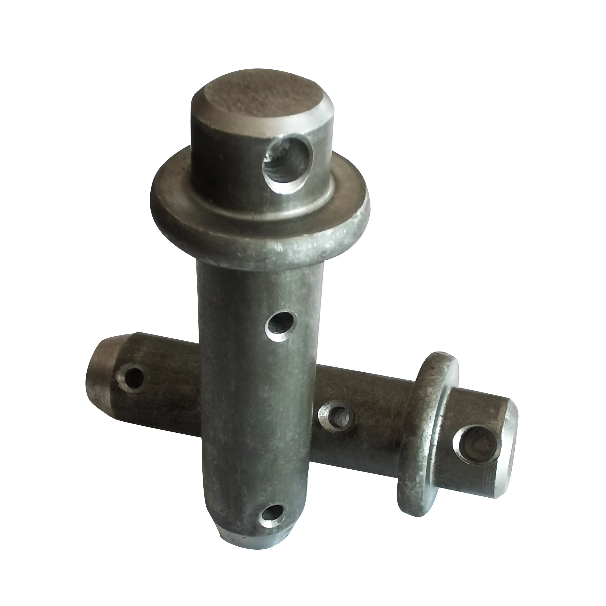
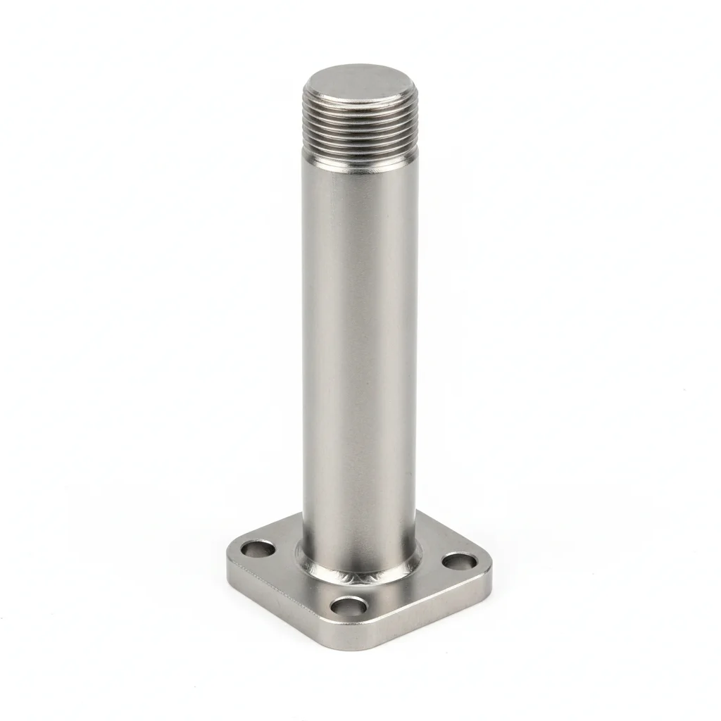
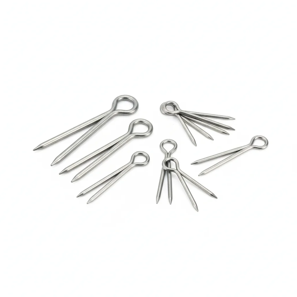
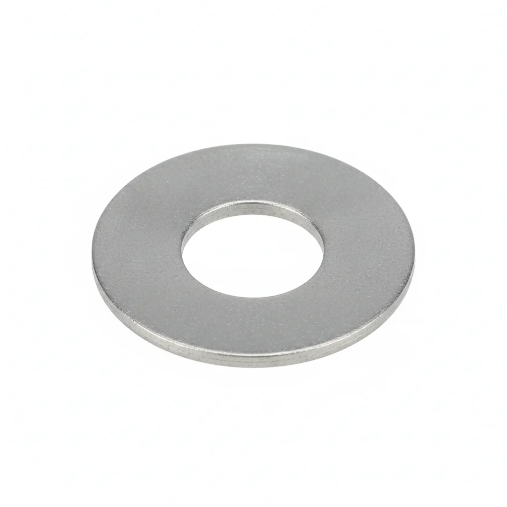
| Suspension Insulator Steel Pin | Post Insulator Base | Pin Insulator Cotter Pin | Ball Head Ring | Flat Washer | |
|---|---|---|---|---|---|
| SPEC | 16-30kN Class | M16-M24 Base Plate | M16-M20 | 16-30kN Class | M10-M12 |
| MATERIAL | Q345B Hot-Dip Galvanized ≥85μm | Cast Iron Hot-Dip Galvanized | Q235B Hot-Dip Galvanized | Q345B Hot-Dip Galvanized | 304 Stainless |
| GRADE | GB/T 1001 | GB/T 8287 | With Cotter Pin | GB/T 2314 | A2 |
| FINISH | HDG >=55um per ISO 1461 | HDG >=55um per ISO 1461 | HDG >=55um per ISO 1461 | HDG >=55um per ISO 1461 | Passivated |
| CORROSION | C3 (ISO 12944-2) | C3 (ISO 12944-2) | C3 (ISO 12944-2) | C3 (ISO 12944-2) | C3 (ISO 12944-2) |
| TEMP | -20°C to +80°C | -20°C to +80°C | -20°C to +80°C | -20°C to +80°C | -20°C to +80°C |
| WEIGHT | ~0.5 kg/piece | ~0.5 kg/piece | ~0.5 kg/piece | ~0.5 kg/piece | ~0.005kg |
| MOQ | 100 pcs | 100 pcs | 100 pcs | 100 pcs | 500 pcs |
| PACK | VCI paper + carton | VCI paper + carton | VCI paper + carton | VCI paper + carton | Plastic bag |
| STD | ISO 898-1, GB/T 3098.1 | ISO 898-1, GB/T 3098.1 | ISO 898-1, GB/T 3098.1 | ISO 898-1, GB/T 3098.1 | ISO 7089 |
| USE | Suspension Insulator | Post Insulator | Pin Insulator | Insulator String Assembly | Load distribution |
PROCEDURE
- Degrease the Q345B pin shank and porcelain interface area with acetone; confirm the HDG layer is free from scratches at the embedment zone.
- Drive the pin into the insulator socket using a nylon-faced mallet; verify full seating so the cotter-pin hole aligns with the cross-hole in the cap.
- Insert the split cotter pin and bend both tails past 90° against the cap; add the spring retaining ring over the bent tails for double anti-withdrawal locking.
- For M16-M24 base plates, set the Q345B bolts with flat washers under head and nut, then torque in a star pattern to the values specified for the bolt grade (e.g., M16 Grade 8.8 80-100 Nm).
- Mark each torqued fastener with torque seal paint and log the torque readings in the QA package.
COMMON ERRORS
| ✕ WRONG | CONSEQUENCE | ✓ CORRECT |
|---|---|---|
| Using a Q235B cotter pin instead of the specified Q235B HDG cotter pin with spring retaining ring | Wind vibration rotates the plain pin out of the groove; conductor slip-off occurs before the next patrol. | Fit the split pin with a spring retaining ring and bend the split tails ≥90° to lock rotation. |
| Skipping the EPDM buffer pad under the post insulator base | Wind-induced sway transmits directly to the M16-M24 bolts, accelerating preload decay and base fatigue. | Place the 3-5mm EPDM pad between base and steel support before torquing to damp vibration. |
| Tightening base bolts without a calibrated torque wrench | Preload scatter exceeds ±15%, leaving some bolts below the retention threshold and prone to loosening. | Use a calibrated wrench and re-torque in a star pattern to the specified Nm range. |
MAINTENANCE
Every two years, re-torque post insulator base bolts to the specified Nm values; at each overhaul window, inspect cotter pins on distribution lines with binoculars or drones and perform ultrasonic thickness checks on steel pins at the porcelain interface, replacing pins thinned by more than 15%.
Plan B · Heavy Pollution/Coastal Reinforcement
C4 Harsh per ISO 12944-2
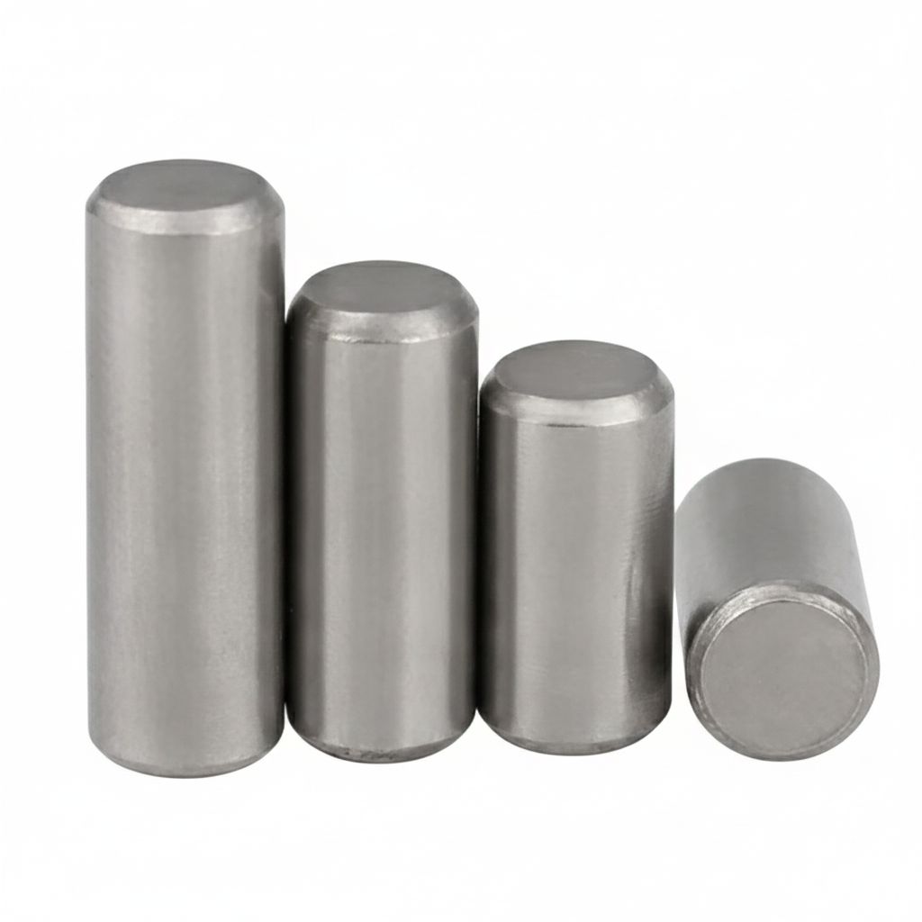
| Steel Pin | Dacromet-Coated Steel Pin | Silicone Rubber Anti-Pollution Insulator Cap | Flat Washer | Flat Washer | |
|---|---|---|---|---|---|
| SPEC | 30-50kN | 30-50kN | Custom | M10-M12 | M10-M12 |
| MATERIAL | 316 Stainless Steel | 42CrMo + Dacromet | 316 Stainless Steel | 304 Stainless | 304 Stainless |
| GRADE | A4-70 | Grade 10.9 | A4-70 | A2 | A2 |
| FINISH | HDG >=55um per ISO 1461 | HDG >=55um per ISO 1461 | HDG >=55um per ISO 1461 | Passivated | Passivated |
| CORROSION | C3 (ISO 12944-2) | C3 (ISO 12944-2) | C3 (ISO 12944-2) | C3 (ISO 12944-2) | C3 (ISO 12944-2) |
| TEMP | -20°C to +80°C | -20°C to +80°C | -20°C to +80°C | -20°C to +80°C | -20°C to +80°C |
| WEIGHT | ~0.5 kg/piece | ~0.5 kg/piece | ~0.5 kg/piece | ~0.005kg | ~0.005kg |
| MOQ | 100 pcs | 100 pcs | 100 pcs | 500 pcs | 500 pcs |
| PACK | VCI paper + carton | VCI paper + carton | VCI paper + carton | Plastic bag | Plastic bag |
| STD | ISO 898-1, GB/T 3098.1 | ISO 898-1, GB/T 3098.1 | ISO 898-1, GB/T 3098.1 | ISO 7089 | ISO 7089 |
| USE | C5 Environment Insulator | Heavy Pollution Area | Anti-Pollution Flashover | Load distribution | Load distribution |
PROCEDURE
- Degrease 316 stainless and 42CrMo + Dacromet surfaces with acetone to remove all oils; verify surface roughness Ra < 3.2 μm.
- Coat threads of A4-70 steel pins and Grade 10.9 Dacromet pins with anti-seize compound rated for -20°C to +150°C; use PTFE-coated washers under heads and nuts.
- Align components per drawing, tighten in cross-pattern sequence to the specified torque for A4-70 (e.g., M16: 80–100 Nm, M20: 180–220 Nm); verify 10% with a calibrated torque wrench.
- Pull-test a 5% random sample of installed pins to 80% of proof load; replace any that slip or fail.
- Apply a weatherproof sealant over exposed threads and install a corrosion monitoring coupon adjacent to critical joints for periodic assessment.
COMMON ERRORS
| ✕ WRONG | CONSEQUENCE | ✓ CORRECT |
|---|---|---|
| Mixing carbon steel fasteners with 316 stainless pins in a coastal assembly | Galvanic corrosion accelerates at the contact points, leading to rapid pitting and premature pin failure within the 20–25 year design life. | Ensure all hardware in the assembly is 316 stainless or Dacromet-coated to maintain corrosion resistance in C4 environments. |
| Using a standard torque value for all fastener sizes without adjusting for grade | Under-torquing Grade 10.9 Dacromet pins can cause loosening under wind vibration; over-torquing A4-70 may strip threads, reducing clamp load. | Follow the specified torque ranges per size and grade (e.g., M16: 80–100 Nm, M20: 180–220 Nm) and verify with a calibrated wrench. |
MAINTENANCE
Inspect insulator hardware seasonally for corrosion, especially at the porcelain-steel interface and cotter pin areas. Re-torque any base bolts that have lost more than 15% of specified torque. Replace steel pins showing pitting depth >0.3mm or surface corrosion affecting >5% of area. At each overhaul window, perform ultrasonic thickness measurement on pins in coastal zones to detect thinning; if thinning exceeds 15%, replace the entire insulator string.
Plan C · Extreme Environment/Offshore Configuration
C5-M Extreme per ISO 12944-2
| Steel Pin | Dacromet-Coated Cotter Pin | Silicone Rubber Anti-Pollution Cap | Epoxy Insulator Base | Anti-Pollution Ball Head Ring | |
|---|---|---|---|---|---|
| SPEC | 50kN Class | M16-M20 | 50kN Class | M20-M24 | 50kN |
| MATERIAL | 316L | 42CrMo + Dacromet | 316L | Epoxy + 316L | 316L |
| GRADE | A4-80 | Grade 10.9 | A4-80 | — | A4-80 |
| FINISH | HDG >=55um per ISO 1461 | HDG >=55um per ISO 1461 | HDG >=55um per ISO 1461 | HDG >=55um per ISO 1461 | HDG >=55um per ISO 1461 |
| CORROSION | C3 (ISO 12944-2) | C3 (ISO 12944-2) | C3 (ISO 12944-2) | C3 (ISO 12944-2) | C3 (ISO 12944-2) |
| TEMP | -20°C to +80°C | -20°C to +80°C | -20°C to +80°C | -20°C to +80°C | -20°C to +80°C |
| WEIGHT | ~0.5 kg/piece | ~0.5 kg/piece | ~0.5 kg/piece | ~0.5 kg/piece | ~0.5 kg/piece |
| MOQ | 100 pcs | 100 pcs | 100 pcs | 100 pcs | 100 pcs |
| PACK | VCI paper + carton | VCI paper + carton | VCI paper + carton | VCI paper + carton | VCI paper + carton |
| STD | ISO 898-1, GB/T 3098.1 | ISO 898-1, GB/T 3098.1 | ISO 898-1, GB/T 3098.1 | ISO 898-1, GB/T 3098.1 | ISO 898-1, GB/T 3098.1 |
| USE | C5-M Suspension Insulator | Heavy Pollution Area Insulator | Anti-Pollution Flashover | Chemical Plant Insulator Base | C5 Environment Insulator String |
PROCEDURE
- Degrease 316L and 42CrMo + Dacromet surfaces with MEK solvent; verify surface roughness Ra < 1.6 μm for optimal coating adhesion.
- Apply marine-grade anti-corrosion compound rated -50°C to +200°C to threads of A4-80 and Grade 10.9 fasteners; use PTFE-encapsulated washers.
- Align components within 0.3mm tolerance; tighten with a hydraulic tensioner to the specified preload for A4-80 (e.g., M20: 180–220 Nm equivalent).
- Perform PMI (Positive Material Identification) on 10% of fasteners to confirm 316L grade; conduct dye penetrant NDT on 10% sample to detect surface cracks.
- Apply protective sealant over all exposed metal surfaces and install permanent condition monitoring instrumentation to track corrosion in real time.
COMMON ERRORS
| ✕ WRONG | CONSEQUENCE | ✓ CORRECT |
|---|---|---|
| Substituting 304 stainless for 316L in offshore hardware | 304 is less resistant to chloride pitting; in C5-M environments, it will corrode rapidly, leading to pin fracture and insulator drop within a shorter period than the 25+ year design life. | Verify material certificates for 316L (A4-80) and use PMI testing to confirm composition before installation. |
| Skipping the application of anti-seize compound on Dacromet cotter pins | Without lubrication, galling can occur during installation, damaging the coating and exposing the 42CrMo substrate to corrosion, compromising cotter pin retention. | Apply a thin layer of marine-grade anti-seize to all threaded and sliding surfaces, including cotter pins, before assembly. |
MAINTENANCE
Conduct continuous condition monitoring via installed sensors; perform visual inspections at each overhaul window for any signs of corrosion or loosening. Replace any fastener showing corrosion affecting >5% of surface area or pitting depth >0.3mm. Annually verify torque on critical base bolts and re-torque if below 80% of specified value. At each major maintenance cycle, perform ultrasonic thickness checks on steel pins at the porcelain interface; replace if thinning exceeds 15%.
SUPPLIER CAPABILITY
Quality, Delivery & Customization
Quality Control
- ✓MTC material certificates with every batch
- ✓Key parts sampled for hardness/salt spray/torque coefficient
- ✓100% inspection or AQL sampling before shipment
Delivery
- ✓Standard parts made to order: 7-15 days
- ✓Custom parts: 25-45 days
- ✓FOB/CIF/DDP supported
Customization
- ✓Drawing review and material matching
- ✓Non-standard sizes/heads/threads
- ✓Small-batch prototyping supported
Certification
- ✓Material certificates (MTC)
- ✓Spectrographic analysis reports
- ✓Salt spray test reports (on request)
MOQ: No MOQ for standard parts; custom parts assessed by process complexity
FAQ
FAQ
RELATED READING
Keep Reading & Next Step
BEYOND TECHNICAL SPECS
Finding the right factory, controlling quality, delivering on time — that's the real challenge. We cover fasteners, rubber, plastics, industrial textiles. One team, end to end.
SEE CAPABILITIES →