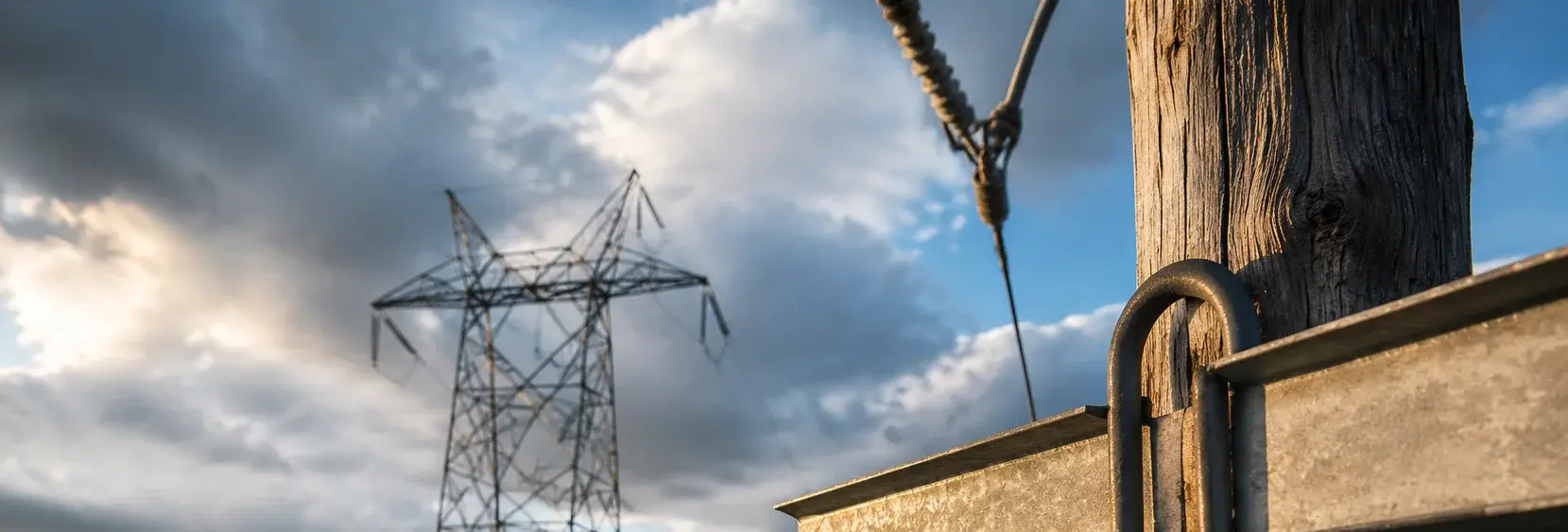
Pole Line Hardware: Material Comparison for Guy and Crossarm Clamps
A pole stands not because of its concrete shaft, but due to the balanced tension of three guy wires. Guy hardware is the 'foundation' of overhead power lines – a single UT clamp failure can bring down an entire pole. This page compares Q235B hot-dip galvanized and 316 stainless steel options for crossarm clamps, UT clamps, wedge clamps, and anchor rods, helping you select the right material for distribution networks (C3) vs coastal/high corrosion (C4-C5) environments
RISK AUDIT // ENGINEERING DIAGNOSIS
Procurement Pitfall Guide
"Real-world failures that lead to pole downfalls."
QC-AUDIT // REV.5
SCALE 1:1 · 03 ITEMS
RISK-01
UT Clamp Adjustment Nut Seized, Preventing Guy Tension Adjustment
Corrective Measures
RISK-02
Wedge Clamp Wedge Loosens Under Vibration
Corrective Measures
RISK-03
Grounding Grid Corrosion Accelerates in Acidic Soil – Ground Resistance Exceeds Limits Yearly
Corrective Measures
FIELD-SPECIFIC INSIGHT
Material Selection Checkpoints for Pole Line Hardware
The choice between Q235B hot-dip galvanized and 316 stainless steel for pole line hardware depends on corrosion environment and mechanical requirements. However, galvanized coatings can be damaged during installation, and stainless steel can suffer from crevice corrosion if not properly specified. Use the table below to verify key parameters before procurement
WHAT TO CHECK
- 1UT clamp adjustment nut: 304 stainless steel bolt in Plan A vs full 316 stainless in Plan B – seized nuts in carbon steel can break during adjustment, requiring costly replacement
- 2Wedge clamp wedge: Q235B galvanized in Plan A vs 42CrMo + Dacromet in Plan B – Dacromet coating provides better corrosion resistance and reduces fretting wear under vibration
- 3Anchor rod: Q235B galvanized in Plan A vs 316L in Plan C – in acidic soil, galvanized coating can corrode faster; specify stainless steel for soil pH <5
- 4Crossarm clamp: Q235B HDG in Plan A vs 316 stainless in Plan B – ensure galvanized coating thickness ≥85μm per ISO 1461 to meet C3 standard
| Check | Why it matters | What to specify |
|---|---|---|
| Corrosion environment class | Determines minimum material and coating requirements; C3 (inland) vs C4-C5 (coastal) per ISO 12944-2 | State ISO 12944-2 class in tender; for C4+, require 316 stainless or Dacromet-coated alloy steel |
| UT clamp adjustment nut material | Carbon steel nuts seize after 2 years outdoors, preventing tension adjustment; stainless steel avoids seizure | Specify 304 or 316 stainless steel for adjustment nut and bolt; avoid carbon steel + galvanized |
| Wedge clamp wedge coating | Galvanized wedge can wear under vibration, reducing clamping force; Dacromet reduces fretting wear | For high-vibration or coastal areas, specify Dacromet-coated wedge (42CrMo + Dacromet) |
| Anchor rod material in acidic soil | Galvanized coating corrodes faster in pH<5 soil; 316L stainless steel resists corrosion | If soil pH <5, specify 316L stainless steel for anchor rod and plate |
All material and coating specifications should be verified against project-specific environmental conditions and applicable standards (GB/T 2314, ISO 1461)
Evidence level: source-page-only
INDUSTRY TECH REFERENCE
Crossarm and Guy Hardware: Installation and Acceptance Parameters
Crossarm clamps, UT guy clamps, and anchor rods each have fixed figures — pin them down at ordering and acceptance.
| Component | Key parameter | Basis |
|---|---|---|
| Crossarm clamp | Bore tolerance ≤2 mm; M16 bolts at 80–100 N·m | Low-preload basis specific to clamps, not the 8.8-grade standard value |
| UT guy clamp | Thread adjustment for tension + double nuts | Back off with double nuts after tensioning to resist vibration loosening |
| Twin crossarm clamps (same pole) | 300–500 mm spacing (recommended) | Arrange by pole loading and span |
| Guy anchor rod & plate | Embedment ≥1.5 m, 2.0 m in soft soil; buried section HDG ≥70 μm | Deepen to 2.0 m in soft soil; check coating tier per GB/T 13912 |
Tolerance, twin-clamp spacing, and embedment depth are KB §2.2.8 recommendations (engineering common sense, magnitude estimates); M16 80–100 N·m is the clamp-specific low-preload figure.
INDUSTRY TECH REFERENCE
Coastal and Acid-Rain Zones: Choosing Guy Hardware Materials
Guy-hardware material follows the corrosivity class of the site — put these three requirements into the inquiry and acceptance.
- Set the corrosivity class first: in C4-C5, choose hot-dip galvanizing ≥70 μm, Dacromet, or 316L
- State the coating tier in the inquiry: GB/T 13912 tiers of 55/70/85 μm — quote and accept against the tier
- In acid-rain zones (pH<5) zinc is consumed markedly faster — prefer 316L or Dacromet for the buried and near-ground sections of the anchor rod
The C4-C5 material basis (§2.2.3) and coating tiers (§6.5) are traced; faster zinc consumption in acid rain follows KB §2.1, consistent with ISO 9223.
PLAN COMPARISON
Three-Plan Core Parameter Comparison
Compare row by row. Click column headers to jump to plan details.
| A · Plan A · Distribution Pole Standard | B · Plan B · Coastal/High Corrosion Reinforcement | C · Plan C · Extreme Environment / Offshore Configuration | |
|---|---|---|---|
| 1. U-SHAPED CROSSARM CLAMP | |||
| SPEC | M16-M20 | M16-M20 | NUT-1~3 |
| MATERIAL | Q235B Hot-Dip Galvanized ≥85μm | 316 Stainless Steel | 316L |
| GRADE | GB/T 2314 | A4-70 | A4-80 |
| FINISH | HDG >=55um per ISO 1461 | HDG >=55um per ISO 1461 | HDG >=55um per ISO 1461 |
| 2. UT GUY CLAMP | |||
| SPEC | NUT-1~NUT-3 | NUT-1~3 | NX-1/2 |
| MATERIAL | 304 Stainless Steel Bolt | 316 Stainless Steel (Full) | 316L |
| GRADE | Adjustable Type | A4-70 | A4-80 |
| FINISH | HDG >=55um per ISO 1461 | HDG >=55um per ISO 1461 | HDG >=55um per ISO 1461 |
| 3. WEDGE GUY CLAMP | |||
| SPEC | NX-1/NX-2 | NX-1/2 | φ16-24mm |
| MATERIAL | Q235B Hot-Dip Galvanized | 42CrMo + Dacromet | 316L |
| GRADE | GB/T 2314 | Grade 10.9 | A4-80 |
| FINISH | HDG >=55um per ISO 1461 | HDG >=55um per ISO 1461 | HDG >=55um per ISO 1461 |
| 4. GUY ANCHOR ROD & PLATE | |||
| SPEC | φ16-24mm | M10-M12 | M16-M20 |
| MATERIAL | Q235B Hot-Dip Galvanized | 304 Stainless | 316L |
| GRADE | GB/T 2314 | A2 | A4-80 |
| FINISH | HDG >=55um per ISO 1461 | Passivated | HDG >=55um per ISO 1461 |
| 5. FLAT WASHER | |||
| SPEC | M10-M12 | M10-M12 | M16-M20 |
| MATERIAL | 304 Stainless | 304 Stainless | 42CrMo + Dacromet |
| GRADE | A2 | A2 | Grade 10.9 |
| FINISH | Passivated | Passivated | HDG >=55um per ISO 1461 |
SELECTION GUIDE
Which Material Fits Your Poles?
| Operating condition | Recommended option | Key basis |
|---|---|---|
| Inland distribution network (C3) | Plan A · Hot-Dip Galvanized Standard | Q235B hot-dip galvanized ≥85μm per ISO 1461, GB/T 2314 |
| Coastal / high corrosion (C4-C5) | Plan B · Full 316 Stainless Steel Reinforcement | 316 stainless (A4-70) or 42CrMo + Dacromet (grade 10.9) |
| Offshore / extreme (C5-M) | Plan C · Extreme Configuration | 316L (A4-80)/duplex steel/titanium alloy per ISO 12944-2 |
| Seized UT clamp nut | Full stainless (304 or above) adjustment bolt and nut | Tighten if guy tension <90% of design value; apply anti-seize compound on threads |
| Wedge loosening under vibration | Lock wedge tail with cotter pin; verify bite depth | Wedge retract >3mm drops clamping force >50%; install armor rods |
| Acidic soil (pH<5) grounding grid | Pure copper or oversized copper-clad steel (copper layer ≥0.5mm) | Replace if copper layer <0.15mm; excavate and inspect every 3 years |
Plan A · Distribution Pole Standard
C3 Standard per ISO 12944-2
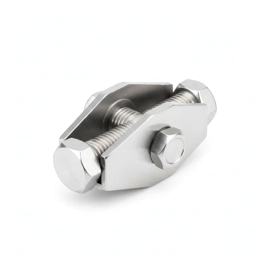
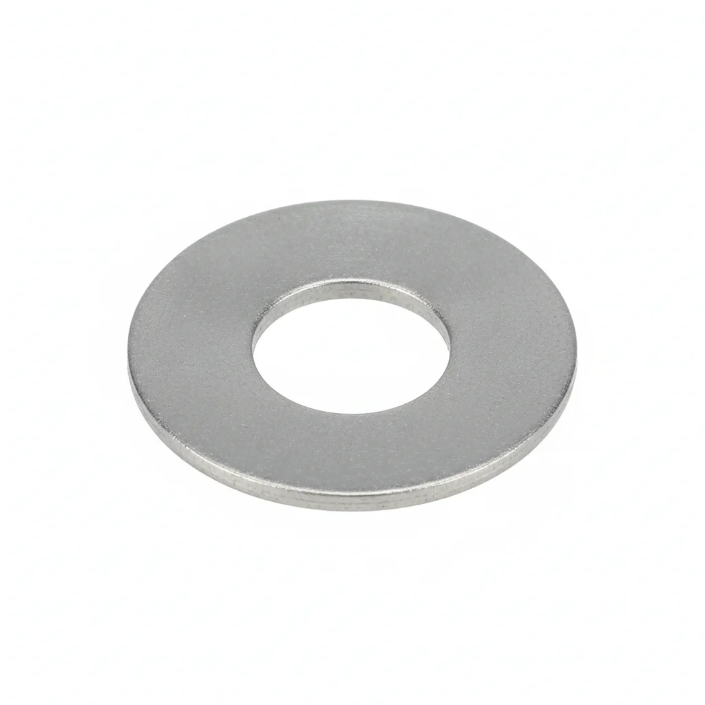
| U-Shaped Crossarm Clamp | UT Guy Clamp | Wedge Guy Clamp | Guy Anchor Rod & Plate | Flat Washer | |
|---|---|---|---|---|---|
| SPEC | M16-M20 | NUT-1~NUT-3 | NX-1/NX-2 | φ16-24mm | M10-M12 |
| MATERIAL | Q235B Hot-Dip Galvanized ≥85μm | 304 Stainless Steel Bolt | Q235B Hot-Dip Galvanized | Q235B Hot-Dip Galvanized | 304 Stainless |
| GRADE | GB/T 2314 | Adjustable Type | GB/T 2314 | GB/T 2314 | A2 |
| FINISH | HDG >=55um per ISO 1461 | HDG >=55um per ISO 1461 | HDG >=55um per ISO 1461 | HDG >=55um per ISO 1461 | Passivated |
| CORROSION | C3 (ISO 12944-2) | C3 (ISO 12944-2) | C3 (ISO 12944-2) | C3 (ISO 12944-2) | C3 (ISO 12944-2) |
| TEMP | -20°C to +80°C | -20°C to +80°C | -20°C to +80°C | -20°C to +80°C | -20°C to +80°C |
| WEIGHT | ~0.5 kg/piece | ~0.5 kg/piece | ~0.5 kg/piece | ~0.5 kg/piece | ~0.005kg |
| MOQ | 100 pcs | 100 pcs | 100 pcs | 100 pcs | 500 pcs |
| PACK | VCI paper + carton | VCI paper + carton | VCI paper + carton | VCI paper + carton | Plastic bag |
| STD | ISO 898-1, GB/T 3098.1 | ISO 898-1, GB/T 3098.1 | ISO 898-1, GB/T 3098.1 | ISO 898-1, GB/T 3098.1 | ISO 7089 |
| USE | Pole crossarm fixation | Guy tension adjustment | Steel strand terminal fixation | Connection from guy to underground anchor plate | Load distribution |
PROCEDURE
- Clean the U-bolt threads and crossarm contact area with a wire brush to remove any debris, then verify the galvanized coating is intact with no bare spots before fitting the U-shaped clamp over the crossarm.
- Position the U-shaped clamp over the crossarm, insert the M16-M20 bolts, and hand-tighten the nuts to seat the clamp evenly against the pole surface.
- Tighten the nuts alternately in a crisscross pattern using a calibrated torque wrench to the specified value for M16-M20 per ISO 898-1, ensuring even load distribution across the crossarm.
- For the UT guy clamp, thread the 304 stainless steel bolt through the NUT-1~NUT-3 body, apply anti-seize compound to the threads, and adjust the nut to achieve initial guy tension, leaving room for future adjustments.
- After final tensioning, verify that the wedge on the NX-1/NX-2 wedge clamp is fully seated and secure the wedge tail with the cotter pin to prevent loosening under vibration.
- Inspect all clamps and anchor rods visually for proper seating, and confirm the galvanized coating thickness meets the ≥55μm requirement per ISO 1461 at critical contact points.
COMMON ERRORS
| ✕ WRONG | CONSEQUENCE | ✓ CORRECT |
|---|---|---|
| Using a carbon steel adjustment nut on the UT clamp instead of the specified 304 stainless steel bolt and nut | The nut seizes due to rust within 2 years outdoors, preventing guy tension adjustment and requiring cutting the bolt with an angle grinder, with repair costs several times the clamp's value. | Ensure the UT clamp adjustment bolt and nut are fully 304 stainless steel, apply anti-seize compound during installation, and reapply after each adjustment. |
| Failing to lock the wedge tail with a cotter pin after installing the wedge clamp | Wind vibration causes the wedge to retract more than 3mm, reducing clamping force by over 50% and allowing the steel strand to slip, leading to guy failure and pole tilt. | After installing the wedge clamp, always lock the wedge tail with a cotter pin and visually verify the wedge bite depth achieves the nominal value with 5-8% strand deformation. |
MAINTENANCE
Annually during line inspection, check guy tension with a tension meter, ensuring it is at least 90% of the design value, and adjust the UT clamp nut if needed, reapplying anti-seize compound. Visually inspect wedge clamps for wedge retraction and cotter pin integrity. Replace any hardware showing corrosion affecting more than 5% of surface area or with galvanized coating damage exceeding the ISO 1461 minimum.
Plan B · Coastal/High Corrosion Reinforcement
C4-C5 coastal / high corrosion per ISO 12944-2
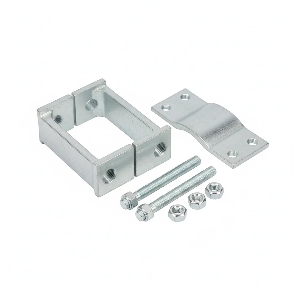
| Crossarm Clamp | UT Guy Clamp | Dacromet Wedge Guy Clamp | Flat Washer | Flat Washer | |
|---|---|---|---|---|---|
| SPEC | M16-M20 | NUT-1~3 | NX-1/2 | M10-M12 | M10-M12 |
| MATERIAL | 316 Stainless Steel | 316 Stainless Steel (Full) | 42CrMo + Dacromet | 304 Stainless | 304 Stainless |
| GRADE | A4-70 | A4-70 | Grade 10.9 | A2 | A2 |
| FINISH | HDG >=55um per ISO 1461 | HDG >=55um per ISO 1461 | HDG >=55um per ISO 1461 | Passivated | Passivated |
| CORROSION | C3 (ISO 12944-2) | C3 (ISO 12944-2) | C3 (ISO 12944-2) | C3 (ISO 12944-2) | C3 (ISO 12944-2) |
| TEMP | -20°C to +80°C | -20°C to +80°C | -20°C to +80°C | -20°C to +80°C | -20°C to +80°C |
| WEIGHT | ~0.5 kg/piece | ~0.5 kg/piece | ~0.5 kg/piece | ~0.005kg | ~0.005kg |
| MOQ | 100 pcs | 100 pcs | 100 pcs | 500 pcs | 500 pcs |
| PACK | VCI paper + carton | VCI paper + carton | VCI paper + carton | Plastic bag | Plastic bag |
| STD | ISO 898-1, GB/T 3098.1 | ISO 898-1, GB/T 3098.1 | ISO 898-1, GB/T 3098.1 | ISO 7089 | ISO 7089 |
| USE | Coastal distribution lines | Coastal guy system | Steel strand fixation in heavy corrosion areas | Load distribution | Load distribution |
PROCEDURE
- Wipe each 316 stainless fitting with a clean rag and solvent to remove any salt or debris from transit; inspect the A4-70 marking on the UT clamp bolt and nut before assembly.
- For the UT clamp, thread the 316 stainless bolt through the guy loop and anchor clevis, then hand-tighten the nut to seat the saddle against the strand.
- Using a calibrated torque wrench, tighten the UT clamp nut in small increments, alternating sides, until the guy tension reaches the design value; confirm the wedge clamp has drawn the strand fully into the socket.
- On the Dacromet wedge clamp (42CrMo, Grade 10.9), verify the wedge is seated to the clamp's nominal depth and secure the cotter pin through the wedge tail.
- Apply anti-seize compound to all 316 stainless threads and to the wedge contact surfaces before final tightening; re-check torque after the first wind or temperature cycle.
- Record torque values and the measured guy tension (≥90% of design) in the installation log for each coastal pole.
COMMON ERRORS
| ✕ WRONG | CONSEQUENCE | ✓ CORRECT |
|---|---|---|
| Mixing a galvanized carbon steel nut onto the 316 stainless UT clamp bolt | Galvanic corrosion at the thread interface seizes the nut within a season, making guy tension adjustment impossible and risking bolt breakage during a storm. | Use the full 316 stainless steel nut and bolt supplied with the Plan B UT clamp; never substitute a galvanized carbon steel nut. |
| Overtightening the Dacromet wedge clamp to the point of crushing the strand | Excessive clamping force deforms the steel strand, reducing its effective cross-section and leading to premature strand failure under cyclic loading. | Tighten the wedge clamp only until the wedge bite reaches the nominal depth (strand deformation of 5-8% of diameter); do not apply extra torque beyond that point. |
| Skipping the cotter pin on the wedge clamp tail | Wind vibration causes the wedge to retract more than 3 mm, dropping clamping force below 50% and allowing the strand to slip out of the guy system. | Always insert and bend the cotter pin through the wedge tail immediately after seating the wedge; verify the pin is intact during each inspection. |
MAINTENANCE
Inspect coastal guy hardware at each seasonal change and after any typhoon or storm event; verify the UT clamp nut turns freely (apply anti-seize if stiff) and check that the wedge cotter pin remains in place. Measure guy tension with a tension meter and re-tighten if below 90% of design value. Examine 316 stainless surfaces for pitting or crevice corrosion at the strand-clamp interface; if corrosion products appear on the Dacromet wedge, replace the wedge before the coating breaks down.
Plan C · Extreme Environment / Offshore Configuration
C5-M extreme / offshore per ISO 12944-2
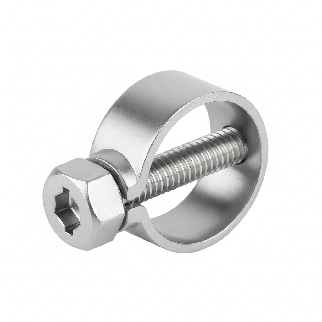
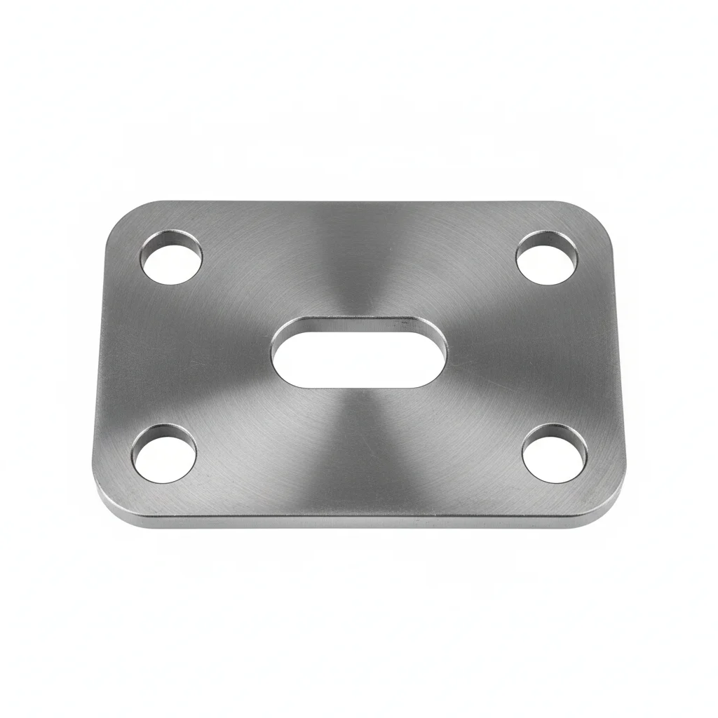
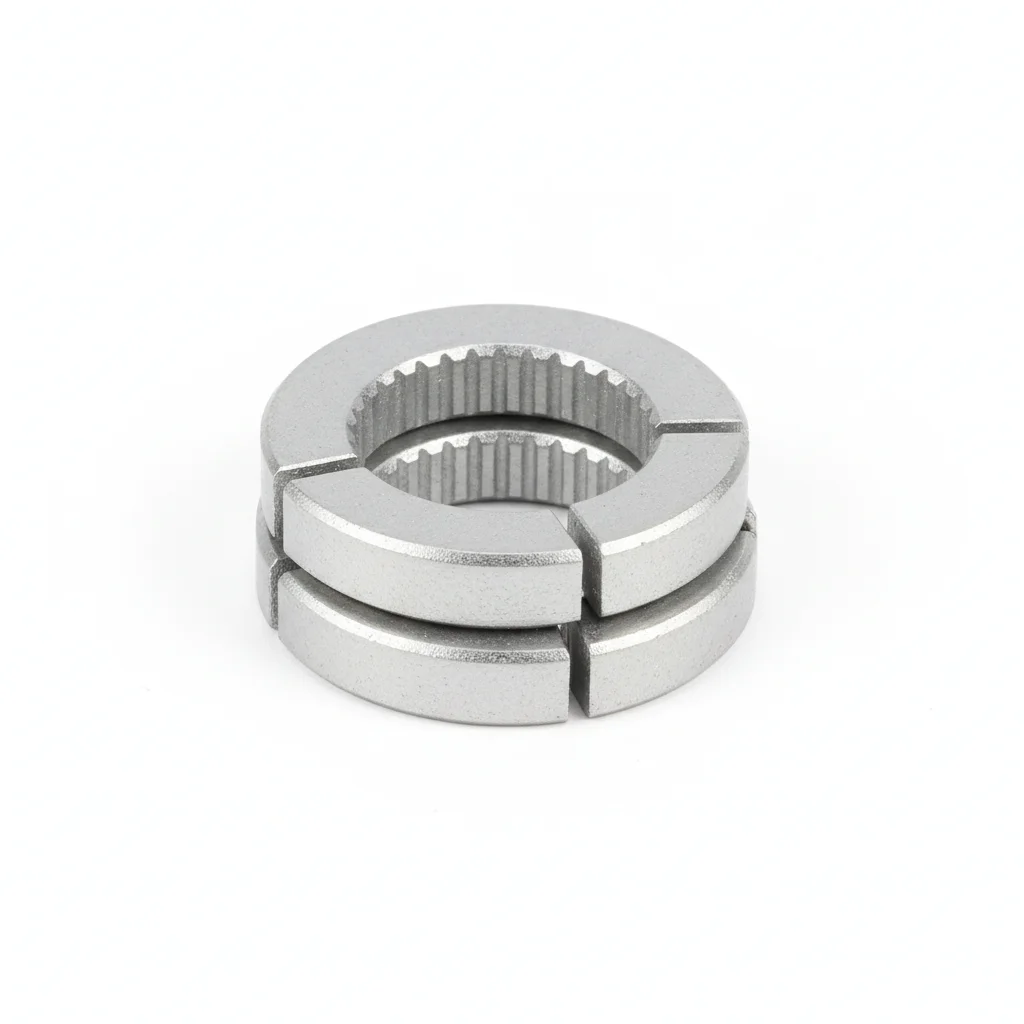
| UT Guy Clamp | Wedge Guy Clamp | Guy Anchor Rod & Plate | Crossarm Clamp | Dacromet Anti-Loosening Washer | |
|---|---|---|---|---|---|
| SPEC | NUT-1~3 | NX-1/2 | φ16-24mm | M16-M20 | M16-M20 |
| MATERIAL | 316L | 316L | 316L | 316L | 42CrMo + Dacromet |
| GRADE | A4-80 | A4-80 | A4-80 | A4-80 | Grade 10.9 |
| FINISH | HDG >=55um per ISO 1461 | HDG >=55um per ISO 1461 | HDG >=55um per ISO 1461 | HDG >=55um per ISO 1461 | HDG >=55um per ISO 1461 |
| CORROSION | C3 (ISO 12944-2) | C3 (ISO 12944-2) | C3 (ISO 12944-2) | C3 (ISO 12944-2) | C3 (ISO 12944-2) |
| TEMP | -20°C to +80°C | -20°C to +80°C | -20°C to +80°C | -20°C to +80°C | -20°C to +80°C |
| WEIGHT | ~0.5 kg/piece | ~0.5 kg/piece | ~0.5 kg/piece | ~0.5 kg/piece | ~0.5 kg/piece |
| MOQ | 100 pcs | 100 pcs | 100 pcs | 100 pcs | 100 pcs |
| PACK | VCI paper + carton | VCI paper + carton | VCI paper + carton | VCI paper + carton | VCI paper + carton |
| STD | ISO 898-1, GB/T 3098.1 | ISO 898-1, GB/T 3098.1 | ISO 898-1, GB/T 3098.1 | ISO 898-1, GB/T 3098.1 | ISO 898-1, GB/T 3098.1 |
| USE | Offshore platform guy tensioning | Offshore steel strand terminal fixation | Offshore grounding system | Offshore distribution lines | Anti-loosening in C5-M environment |
PROCEDURE
- Degrease all 316L and duplex fittings with MEK solvent and verify surface roughness Ra <1.6 μm; confirm A4-80 grade markings on each UT clamp, wedge clamp, and anchor rod.
- Assemble the UT guy clamp using 316L components, apply marine-grade anti-seize compound to the threads, and hand-thread the nut to avoid cross-threading.
- Tighten the UT clamp nut with a hydraulic tensioner in a cross-pattern sequence, monitoring the load cell until the guy tension reaches the design value; verify with a calibrated torque wrench.
- For the 316L wedge clamp, drive the wedge into the socket until the strand is gripped at the nominal depth; secure the wedge tail with a cotter pin and apply a protective sealant over the wedge opening.
- PMI verify 10% of the installed fasteners (using a handheld XRF analyzer) to confirm material grade is 316L or duplex as specified.
- Record installation torque, tension readings, and PMI results in the compliance audit log for each offshore pole.
COMMON ERRORS
| ✕ WRONG | CONSEQUENCE | ✓ CORRECT |
|---|---|---|
| Using a 304 stainless washer under a 316L bolt head in a salt-laden offshore atmosphere | The less corrosion-resistant 304 washer corrodes preferentially, creating a crevice that accelerates attack on the 316L bolt and can lead to premature loosening. | Use only 316L or duplex washers (e.g., Dacromet anti-loosening washers) that match the fastener grade in the C5-M environment. |
| Failing to apply sealant to the wedge clamp opening after installation | Salt spray and moisture enter the wedge-strand interface, causing crevice corrosion that weakens the strand and reduces the wedge's grip over time. | After seating the wedge and securing the cotter pin, apply a marine-grade sealant around the wedge opening to exclude moisture and contaminants. |
| Overtorquing the 316L UT clamp nut beyond the A4-80 proof stress | The bolt yields or fractures at the thread root, causing sudden loss of guy tension and potential pole failure during high wind. | Tighten the UT clamp nut to the specified torque value for A4-80 fasteners using a calibrated hydraulic tensioner; never exceed the rated proof load. |
MAINTENANCE
Schedule inspection of offshore guy hardware at each platform maintenance window and after any extreme weather event; check the UT clamp nut for free rotation and re-apply anti-seize if needed. Verify the wedge clamp cotter pin is intact and inspect for any sign of wedge retraction beyond allowable limits. Use a tension meter to confirm guy tension remains ≥90% of design value. Perform dye penetrant NDT on 10% of the 316L fasteners annually to detect stress corrosion cracking; replace any fastener showing crack indications immediately.
SUPPLIER CAPABILITY
Quality, Delivery & Customization
Quality Control
- ✓MTC material certificates with every batch
- ✓Key parts sampled for hardness/salt spray/torque coefficient
- ✓100% inspection or AQL sampling before shipment
Delivery
- ✓Standard parts made to order: 7-15 days
- ✓Custom parts: 25-45 days
- ✓FOB/CIF/DDP supported
Customization
- ✓Drawing review and material matching
- ✓Non-standard sizes/heads/threads
- ✓Small-batch prototyping supported
Certification
- ✓Material certificates (MTC)
- ✓Spectrographic analysis reports
- ✓Salt spray test reports (on request)
MOQ: No MOQ for standard parts; custom parts assessed by process complexity
FAQ
FAQ
RELATED READING
Keep Reading & Next Step
BEYOND TECHNICAL SPECS
Finding the right factory, controlling quality, delivering on time — that's the real challenge. We cover fasteners, rubber, plastics, industrial textiles. One team, end to end.
SEE CAPABILITIES →