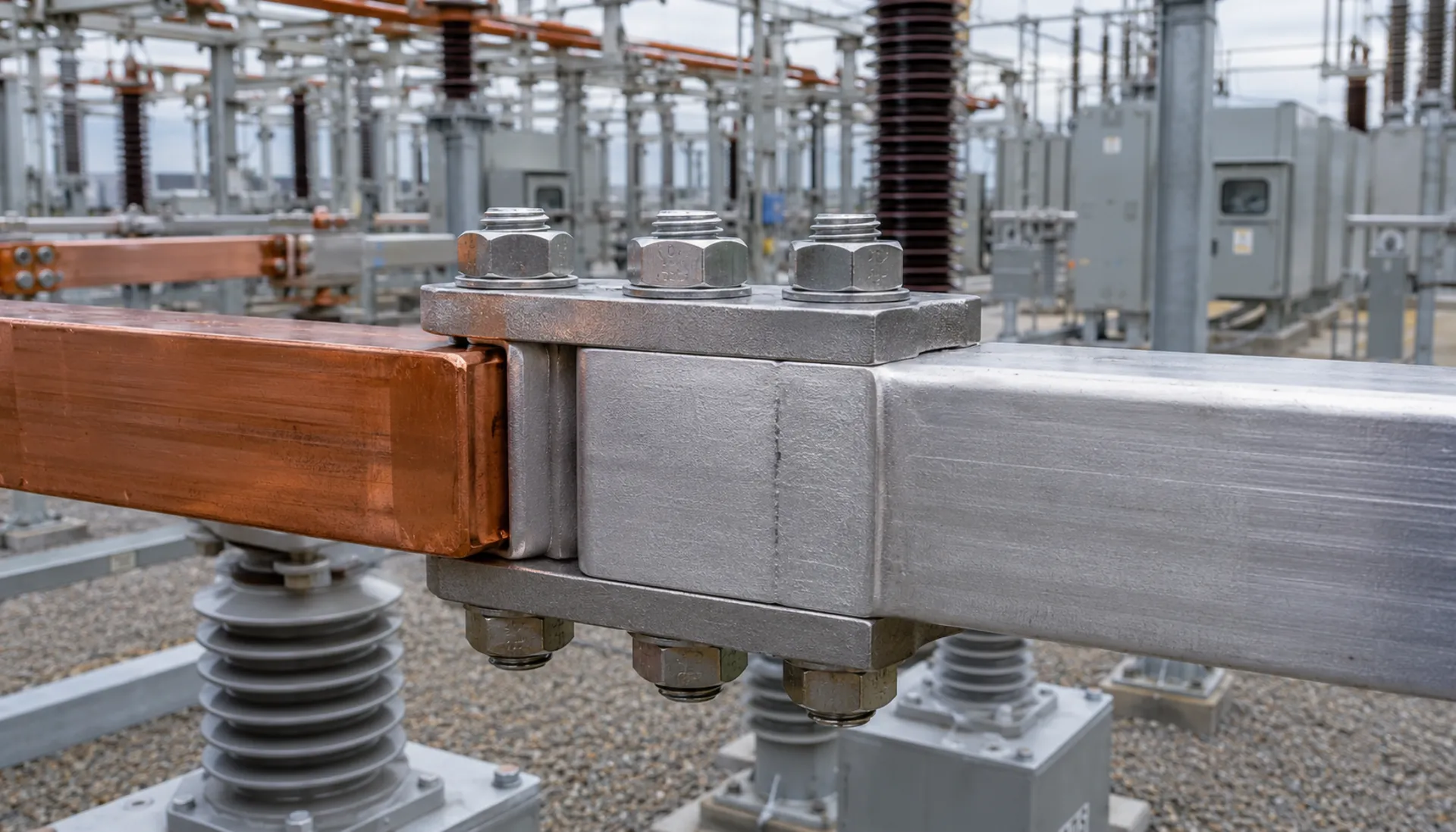
Substation Connector Overheating: Prevention Through Hardware Selection
Copper-aluminum transition clamps in substations fail when Al₂O₃ layer growth increases contact resistance from <5μΩ to 50-100μΩ, causing joint temperatures to rise from 50°C to 150°C. Friction-welded interfaces (>80MPa strength) resist this degradation better than brazed joints (30-50MPa)
RISK AUDIT // ENGINEERING DIAGNOSIS
Procurement Pitfall Avoidance Guide
"Field failures in substations often trace back to overlooked details in connector selection and installation."
QC-AUDIT // REV.5
SCALE 1:1 · 03 ITEMS
RISK-01
Overheating Due to Oxidation of Equipment Clamp Contact Surface
Corrective Measures
RISK-02
Contact Surface Oxidation of Copper-Aluminum Transition Clamps During Temperature Cycling
Corrective Measures
RISK-03
Excessive Contact Resistance at Substation Grounding Grid and Equipment Connection Points
Corrective Measures
FIELD-SPECIFIC INSIGHT
Critical Checks for Substation Connector Procurement
The most overlooked engineering difference in substation connectors is the welding process for copper-aluminum transitions. Friction welding produces interface strength ≥80MPa, while brazing yields only 30-50MPa due to melting point mismatch. This directly impacts long-term contact resistance stability under thermal cycling
WHAT TO CHECK
- 1Specify friction-welded copper-aluminum transition clamps (interface strength ≥80MPa) to avoid brazed joint degradation (30-50MPa) that accelerates oxidation
- 2Require initial contact resistance <5μΩ per joint; monitor ΔT>30°C via infrared thermography as per Q/GDW 11399 for de-energized maintenance
- 3Verify coating thickness on threads and contact surfaces
- 4For tubular bus hardware, ensure clamp design accommodates thermal expansion mismatch (Cu 16. 5e-6 vs Al 23. 6e-6) to prevent micro-slip and oxidation
| Check | Why it matters | What to specify |
|---|---|---|
| Welding process of copper-aluminum transition | Friction welding (≥80MPa) vs brazing (30-50MPa) determines long-term contact resistance stability under thermal cycling | Require friction-welded interface with minimum tensile strength ≥80MPa per material certificate |
| Initial contact resistance | Low initial resistance (<5μΩ) ensures minimal heating; rise to >50μΩ indicates oxidation and risk of thermal runaway | Specify maximum contact resistance <5μΩ at installation; require test report per IEC 61238 |
| Coating thickness and coverage | Thin coating leads to rust and increased resistance | Specify hot-dip galvanizing per ISO 1461 with minimum 55μm on all surfaces; verify with magnetic thickness gauge |
| Thermal expansion compatibility | Copper and aluminum expand at different rates; clamps must allow movement to avoid micro-slip and oxidation | Design clamp with spring washers or slotted holes to accommodate differential expansion; specify torque values per manufacturer |
Data based on page content: Al₂O₃ resistivity >10¹⁴Ω·cm, contact resistance rise from <5μΩ to 50-100μΩ, temperature rise from 50°C to 150°C. Verify all values with project-specific calculations
Evidence level: source-page-only
INDUSTRY TECH REFERENCE
Three Joining Processes: How to Verify Bond Strength
Cu-Al transition, grounding, and line hardware each use a different process with its own acceptance check.
| Process | Where it applies | Bond/crimp strength | Acceptance basis |
|---|---|---|---|
| Friction welding | Cu-Al transition clamps (busbar-to-busbar, equipment terminals) | Bond strength ≥90% of parent metal | Require friction-weld process certificate; convert from parent-metal tensile |
| Exothermic welding | Grounding joints (copper-clad steel rods, copper braid) | Bond strength ≥90% | Sample weld coupons on site for testing |
| Hydraulic crimping | Line hardware (tension and splice clamps) | Pump pressure ≥80 MPa, elongation ≥15% (magnitude estimate) | Manufacturing acceptance per DL/T 768.7 |
≥90% for friction/exothermic welds and ≥15% elongation are magnitude-stated (process/engineering common sense); 80 MPa is the hydraulic pump-pressure figure (traced).
INDUSTRY TECH REFERENCE
Substation Grounding Joints: Three Numbers Decide Acceptance
Accept grounding joints against these three criteria — skip one and fault/lightning current discharge is at risk.
- Substation ground resistance ≤0.5 Ω (GB 50065, effectively grounded systems) — a bad joint will fail before the main grid does
- Copper-clad steel ground rods need a copper layer ≥0.25 mm — too thin and the steel shows through early in soil (magnitude-stated)
- Exothermic weld bond strength ≥90% (magnitude-stated) — never use power-frequency bolted joints on the ground main
- Scope per the capability line: copper-clad steel rods + exothermic weld molds + copper braid
0.25 mm and ≥90% are magnitude-stated (process/engineering common sense); ≤0.5 Ω is traced to GB 50065.
INDUSTRY TECH REFERENCE
Incoming Inspection: Three-Tool Anti-Fraud Kit for Bus Connections
Bus-connection bolts are a fraud hotspot — re-verify everything on delivery with these three tools.
- Demand a torque-coefficient report — mandatory for bus connection bolts (copper/tin-plated steel, M10-M12)
- Spectrometer material check — 304 passed off as 316L, 6063 as 6061 are real industry pains
- Measure coating thickness with a micrometer — nominal 65 μm vs actual 40 μm happens
- Add hardness spot checks — spectrometer + micrometer + hardness together
The 65/40 μm nominal-vs-actual and material-substitution cases are KB industry procurement facts; M10-M12 is the typical bus-bolt range.
SELECTION GUIDE
Selection Decision Aid
| Operating condition | Recommended option | Key basis |
|---|---|---|
| Copper bar 50×6~aluminum bar 80×8 transition | SLG-400 friction-welded copper-aluminum transition clamp | Friction weld interface ≥80MPa, conductivity ≥97% IACS, initial contact resistance <5μΩ |
| Equipment terminal connection (LGJ-630/800) | SYG-630 / SYG-800 equipment clamps | Aluminum alloy + copper-aluminum transition structure |
| Tubular bus / flexible bus fixing | MGH tubular busbar clamp + flexible busbar clamp | Tubular bus Φ100-250mm, current rating 2000-8000A |
| Overheating from contact oxidation | Friction or explosion welding (mechanical crimping prohibited) | Al₂O₃ resistivity >10¹⁴Ω·cm, contact resistance <5μΩ→50-100μΩ; ΔT>30°C de-energize per Q/GDW 11399 |
| Grounding grid connection resistance | Exothermic welding or copper-aluminum transition joints | Contact resistance <10mΩ initially, redo if >50mΩ; excavate and sample every 2 years |
| Micro-slip from thermal cycling (Cu 16.5e-6 vs Al 23.6e-6) | Tin-plate contact surface + conductive grease + disc spring washers | Annual infrared inspection, treat if ΔT>10K; disassemble and re-grind every 5 years |
① Copper-Aluminum Transition Clamp
C3 (ISO 12944-2) indoor/outdoor substation environment
| SLG-400 Copper-Aluminum Transition | SYG-630 Equipment Clamp | SYG-800 Equipment Clamp | |
|---|---|---|---|
| SPEC | Applicable Copper Bar 50×6~Aluminum Bar 80×8 | Applicable Conductor LGJ-630 | Applicable Conductor LGJ-800 |
| MATERIAL | T2 Copper + 1060 Aluminum, Friction Weld | Aluminum Alloy + Copper-Aluminum Transition | Aluminum Alloy + Copper-Aluminum Transition |
| GRADE | — | — | — |
| FINISH | HDG >=55um per ISO 1461 | HDG >=55um per ISO 1461 | HDG >=55um per ISO 1461 |
| CORROSION | C3 (ISO 12944-2) | C3 (ISO 12944-2) | C3 (ISO 12944-2) |
| TEMP | -20°C to +80°C | -20°C to +80°C | -20°C to +80°C |
| WEIGHT | ~0.5 kg/piece | ~0.5 kg/piece | ~0.5 kg/piece |
| MOQ | 100 pcs | 100 pcs | 100 pcs |
| PACK | VCI paper + carton | VCI paper + carton | VCI paper + carton |
| STD | ISO 898-1, GB/T 3098.1 | ISO 898-1, GB/T 3098.1 | ISO 898-1, GB/T 3098.1 |
| USE | Copper-Aluminum Bar Transition Connection | Equipment Terminal Connection | Large Cross-Section Equipment Connection |
PROCEDURE
- Clean the copper and aluminum surfaces with acetone to remove oil and oxide film; check flatness to within 0.1 mm per 100 mm.
- Apply a thin layer of conductive grease to the contact faces; position the SLG or SYG clamp and insert the bolts with Belleville washers.
- Tighten the bolts in a cross pattern to the torque specified by the manufacturer; verify with a calibrated torque wrench.
- After assembly, measure the contact resistance across the joint with a micro-ohmmeter; ensure it is below the specified maximum of 5 μΩ.
- Mark the bolts with torque seal paint and record the installation data in the QA log.
COMMON ERRORS
| ✕ WRONG | CONSEQUENCE | ✓ CORRECT |
|---|---|---|
| Using a brazed copper-aluminum transition instead of friction-welded | Interface strength only 30-50 MPa, prone to cracking and increased contact resistance under thermal cycling, leading to overheating and failure. | Specify friction-welded transitions with interface strength ≥80 MPa; verify via material certificate. |
| Overtightening the bolts without using a torque wrench | Can cause thread damage or excessive stress on the aluminum, leading to premature failure. | Use a calibrated torque wrench and follow the manufacturer's specified torque values; re-check after thermal cycling. |
MAINTENANCE
Perform annual infrared thermography; if temperature rise exceeds 10 K above ambient, de-energize and re-torque. Disassemble and re-grind contact surfaces every 5 years.
② Tubular Bus Hardware
C4 Harsh per ISO 12944-2
| MGH Tubular Busbar Fixing Clamp | Flexible Busbar Fixing Clamp | |
|---|---|---|
| SPEC | For tubular bus Φ100-250mm | For 2000-8000A applications |
| MATERIAL | Aluminum alloy | Aluminum alloy |
| GRADE | — | — |
| USE | Tubular busbar fixed support | Flexible busbar fixing & connection |
PROCEDURE
- Degrease the tubular bus contact areas with acetone to remove any film; verify surface roughness Ra <3.2 µm.
- Apply anti-corrosion joint compound rated for -20°C to 150°C on the bus and clamp interfaces; use PTFE-coated washers under bolt heads and nuts.
- Align the MGH clamp on the Φ100–250mm bus, then tighten in a cross-pattern sequence to the specified torque; check 10% of bolts with a verification tool and log ambient conditions.
- Pull-test a 5% random sample of clamps to 80% of proof load; replace any that fall below the acceptance threshold.
- Apply a weatherproof protective coating over the clamp assembly and install a corrosion monitoring coupon adjacent to critical joints.
COMMON ERRORS
| ✕ WRONG | CONSEQUENCE | ✓ CORRECT |
|---|---|---|
| Using a brazed copper-aluminum transition in a high-current tubular bus connection | Interface strength only 30-50MPa leads to micro-slip under thermal cycling, raising contact resistance from <5µΩ toward 50-100µΩ and causing overheating above 150°C. | Specify friction-welded transitions with interface strength ≥80MPa, as used in SLG and SYG series, for all copper-aluminum joints. |
| Skipping conductive grease on the contact surfaces of the MGH clamp | Al₂O₃ oxide layer grows on aluminum surfaces, increasing contact resistance and causing temperature rise from 50°C to 150°C under 4000A load. | Apply a conductive joint compound rated for -20°C to 150°C to all contact interfaces before tightening. |
| Tightening bolts without a calibrated torque wrench or in random order | Uneven clamping force causes differential thermal expansion (Cu 16.5e-6 vs Al 23.6e-6) to loosen joints, accelerating oxidation and resistance rise. | Use a calibrated torque wrench (±3%) and follow a cross-pattern sequence to ensure even load distribution. |
MAINTENANCE
During each overhaul window, perform infrared thermography on all tubular bus clamps and treat any joint with ΔT>30°C per Q/GDW 11399. Disassemble and re-grind contact surfaces every 5 years, and verify coating thickness (HDG ≥55µm per ISO 1461) on exposed hardware.
REFERENCED STANDARDS
Technical Basis and Reference Standards
SUPPLIER CAPABILITY
Quality, Delivery & Customization
Quality Control
- ✓MTC material certificates with every batch
- ✓Key parts sampled for hardness/salt spray/torque coefficient
- ✓100% inspection or AQL sampling before shipment
Delivery
- ✓Standard parts made to order: 7-15 days
- ✓Custom parts: 25-45 days
- ✓FOB/CIF/DDP supported
Customization
- ✓Drawing review and material matching
- ✓Non-standard sizes/heads/threads
- ✓Small-batch prototyping supported
Certification
- ✓Material certificates (MTC)
- ✓Spectrographic analysis reports
- ✓Salt spray test reports (on request)
MOQ: No MOQ for standard parts; custom parts assessed by process complexity
FAQ
Frequently Asked Questions
RELATED READING
Keep Reading & Next Step
BEYOND TECHNICAL SPECS
Finding the right factory, controlling quality, delivering on time — that's the real challenge. We cover fasteners, rubber, plastics, industrial textiles. One team, end to end.
SEE CAPABILITIES →