
Vibration Damper & Spacer Hardware Selection
Aeolian vibration (10-50Hz) causes conductor fatigue at suspension clamps. Compare Plan A (Stockbridge damper + spiral damping line) for spans ≤300m and Plan B (bundle spacer with damping) for 220-500kV. Each damper costs tens of dollars but protects conductors worth tens of thousands. Key procurement checks: installation position within tolerance, clamp force control, material grade for environment
RISK AUDIT // ENGINEERING DIAGNOSIS
Procurement Pitfall Guide
"Field failures that silently shorten conductor life."
QC-AUDIT // REV.5
SCALE 1:1 · 03 ITEMS
RISK-01
Ineffective Protection Due to Incorrect Damper Installation Position
Corrective Measures
RISK-02
Damper Clamp Abrasion on Conductors
Corrective Measures
RISK-03
Accelerated Ground Grid Corrosion in Acidic Soil – Ground Resistance Exceeds Limits Yearly
Corrective Measures
FIELD-SPECIFIC INSIGHT
Critical Procurement Checks for Vibration Damper Hardware
Vibration dampers and spacers are mechanical hardware that must be precisely installed to avoid conductor damage. The most overlooked engineering difference is the installation position tolerance: a deviation from the antinode reduces damping effectiveness. Additionally, clamp force must be controlled to prevent strand indentation or sliding
WHAT TO CHECK
- 1Installation position: Damper must be at antinode (max amplitude point); deviation reduces damping effectiveness
- 2Clamp force: Excessive force embeds aluminum clamp into strands → stress concentration → reduced fatigue life; insufficient force causes sliding
- 3Material grade: For offshore C5-M environment, use 316L stainless steel to avoid galvanic corrosion
- 4Bundle conductor spacers: For 220kV twin bundle (FJZ-2) and 500kV quad bundle (FJZ-4), ensure anodized aluminum alloy for corrosion resistance
- 5Interphase spacers: FRP core + silicone rubber for anti-galloping; verify insulating properties and mechanical strength per phase spacing
| Check | Why it matters | What to specify |
|---|---|---|
| Damper installation position relative to antinode | Deviation reduces damping effectiveness; incorrect position may cause no damping | Require calculation of antinode position based on span length and conductor type; field verification with vibration measurement |
| Clamp force on conductor | Too low causes sliding and loss of damping position; too high embeds clamp into strands | Specify maximum clamping force as percentage of conductor breaking strength; use torque wrench with calibrated setting |
| Material grade for environment | Offshore C5-M requires 316L stainless steel to prevent corrosion | State environment classification (ISO 12944-2) and require material certificate for damper clamp, spacer body, and fasteners |
| Compliance with IEC 61897 | Standard specifies performance requirements for Stockbridge dampers; non-compliant dampers may not provide rated damping | Require type test report per IEC 61897 including damping capacity, fatigue test, and clamp slip test |
All numerical values are from the source page. Verify with project-specific conductor data and environmental conditions
Evidence level: source-page-only
INDUSTRY TECH REFERENCE
How a Stockbridge Damper Is Tuned and Where It Goes
A damper works only if tuned and placed correctly — hanging it is not enough.
A Stockbridge damper is a tuned mass damper: weights on a steel spring blade, tuned to the aeolian-vibration frequency of the conductor, absorbing energy at the suspension-clamp exit. Placement follows the span; typically 400–600 mm from the clamp end (magnitude estimate) — calculate the position from conductor type and span before installing, do not eyeball it.
The 400–600 mm placement is a KB magnitude estimate (§2.2.6).
INDUSTRY TECH REFERENCE
Damper and Clamp Materials: Corrosion Acceptance Checks
The damper body, clamps, and their bolts each carry a corrosion specification — pin each down at ordering and acceptance.
| Component | Material / corrosion basis | Notes |
|---|---|---|
| Damper clamp bolts | 304 stainless steel | Typical standard for clamp bolts; upgrade per C4-C5 in coastal service |
| Damper body & clamps (coastal C4-C5) | HDG ≥70 μm, Dacromet, or 316L | Pick one of the three by environment and budget |
| Galvanized parts on delivery | Check the tier per GB/T 13912 (55/70/85 μm) | Measure coating thickness; do not accept a composition report alone |
304 as the standard clamp-bolt grade (§5), the C4-C5 material basis (§2.2.3), and coating tiers (§6.5) are all traced.
INDUSTRY TECH REFERENCE
Anti-Vibration and Fitting Standards to Check
Cross-check the inquiry and acceptance against these standards — do not accept against the wrong one.
PLAN COMPARISON
Three-Plan Core Parameter Comparison
Compare row by row. Click column headers to jump to plan details.
| A · Plan A · Standard Conductor Vibration Damping | B · Plan B · Bundle Conductor Spacer + Damping | C · Plan C · Extreme Environment / Offshore Configuration | |
|---|---|---|---|
| 1. STOCKBRIDGE VIBRATION DAMPER | |||
| SPEC | FD-1~FD-5 | Type FJZ-2 | FD Series |
| MATERIAL | Cast Iron + Aluminum Alloy Clamp | Aluminum Alloy | 316L |
| GRADE | Hot-Dip Galvanized | Anodized | A4-80 |
| FINISH | HDG >=55um per ISO 1461 | HDG >=55um per ISO 1461 | HDG >=55um per ISO 1461 |
| 2. SPIRAL DAMPING LINE | |||
| SPEC | Auxiliary for spans >500m | Type FJZ-4 | Quad Bundle FJZ-4 |
| MATERIAL | Aluminum Alloy Spiral Wrap | Aluminum Alloy | 316L |
| GRADE | — | Anodized | A4-80 |
| FINISH | HDG >=55um per ISO 1461 | HDG >=55um per ISO 1461 | HDG >=55um per ISO 1461 |
| 3. ARMOR RODS | |||
| SPEC | Armor Rod, per conductor type | Customized per phase spacing | Customized per conductor |
| MATERIAL | Aluminum Alloy | FRP Core + Silicone Rubber | 316L Stainless Steel |
| GRADE | — | Insulating | A4-80 |
| FINISH | HDG >=55um per ISO 1461 | HDG >=55um per ISO 1461 | HDG >=55um per ISO 1461 |
| 4. FLAT WASHER | |||
| SPEC | M10-M12 | M10-M12 | Per phase spacing |
| MATERIAL | 304 stainless steel | 304 Stainless | FRP+316L |
| GRADE | A2 | A2 | — |
| FINISH | Passivated | Passivated | HDG >=55um per ISO 1461 |
| 5. FLAT WASHER | |||
| SPEC | M10-M12 | M10-M12 | Per conductor type |
| MATERIAL | 304 Stainless | 304 Stainless | 316L |
| GRADE | A2 | A2 | A4-80 |
| FINISH | Passivated | Passivated | HDG >=55um per ISO 1461 |
SELECTION GUIDE
Still Unsure Which Damping Hardware Fits Your Line?
| Operating condition | Recommended option | Key basis |
|---|---|---|
| Single conductor, span ≤300m | Plan A · Standard Conductor Vibration Damping | Stockbridge damper FD-1~FD-5 hot-dip galvanized for LGJ 50-400, per IEC 61897 |
| Bundle conductor 220-500kV | Plan B · Bundle Spacer + Vibration Damper | FJZ-2 twin (220kV) / FJZ-4 quad (500kV), anodized aluminum alloy |
| Offshore / extreme (C5-M) | Plan C · Extreme Configuration | 316L (A4-80)/duplex steel/titanium alloy per ISO 12944-2 |
| Incorrect damper installation position | Calculate antinode from span length and conductor type | Deviation >0.3m reduces damping >50%; install 0.5-1.5m from suspension clamp exit |
| Clamp force control on conductor | Use torque wrench (40-60 Nm) + pre-installed armor rods | Clamping force >20% of breaking strength embeds strands; check slip marks after 3 months |
| Acidic soil (pH<5) grounding | Pure copper or oversized copper-clad steel (copper layer ≥0.5mm) | Replace if copper layer <0.15mm; excavate and inspect every 3 years |
Plan A · Standard Conductor Vibration Damping
C3 (ISO 12944-2) for inland spans ≤300m; HDG ≥55μm per ISO 1461.
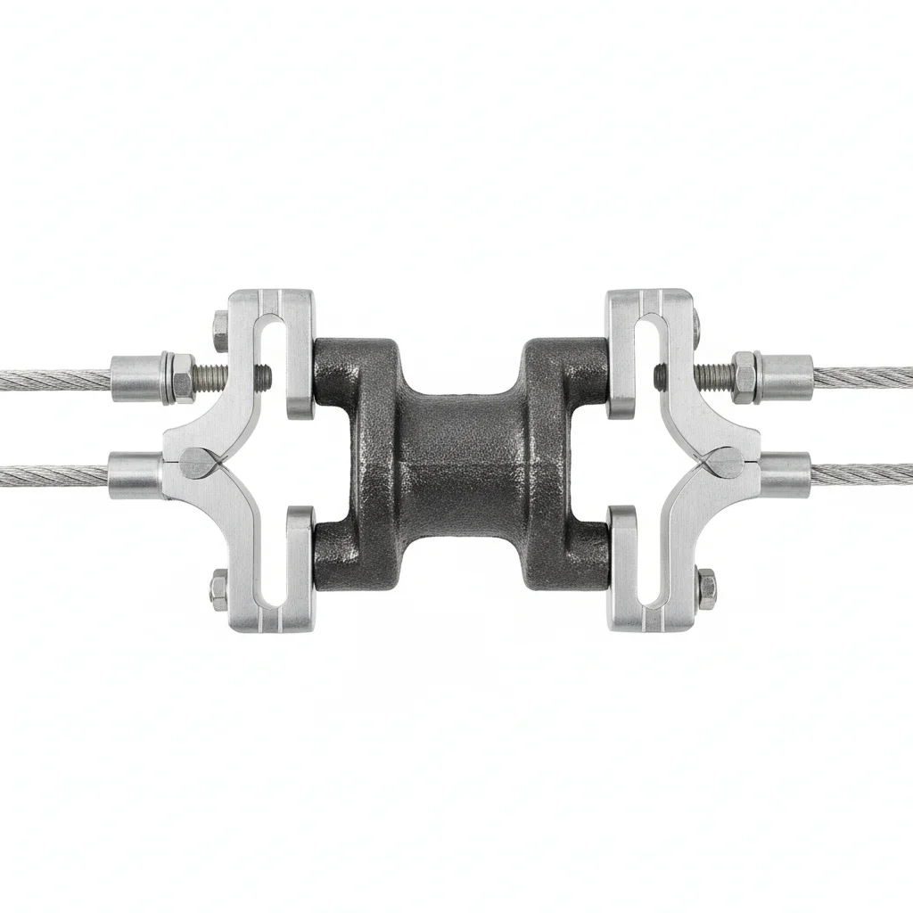
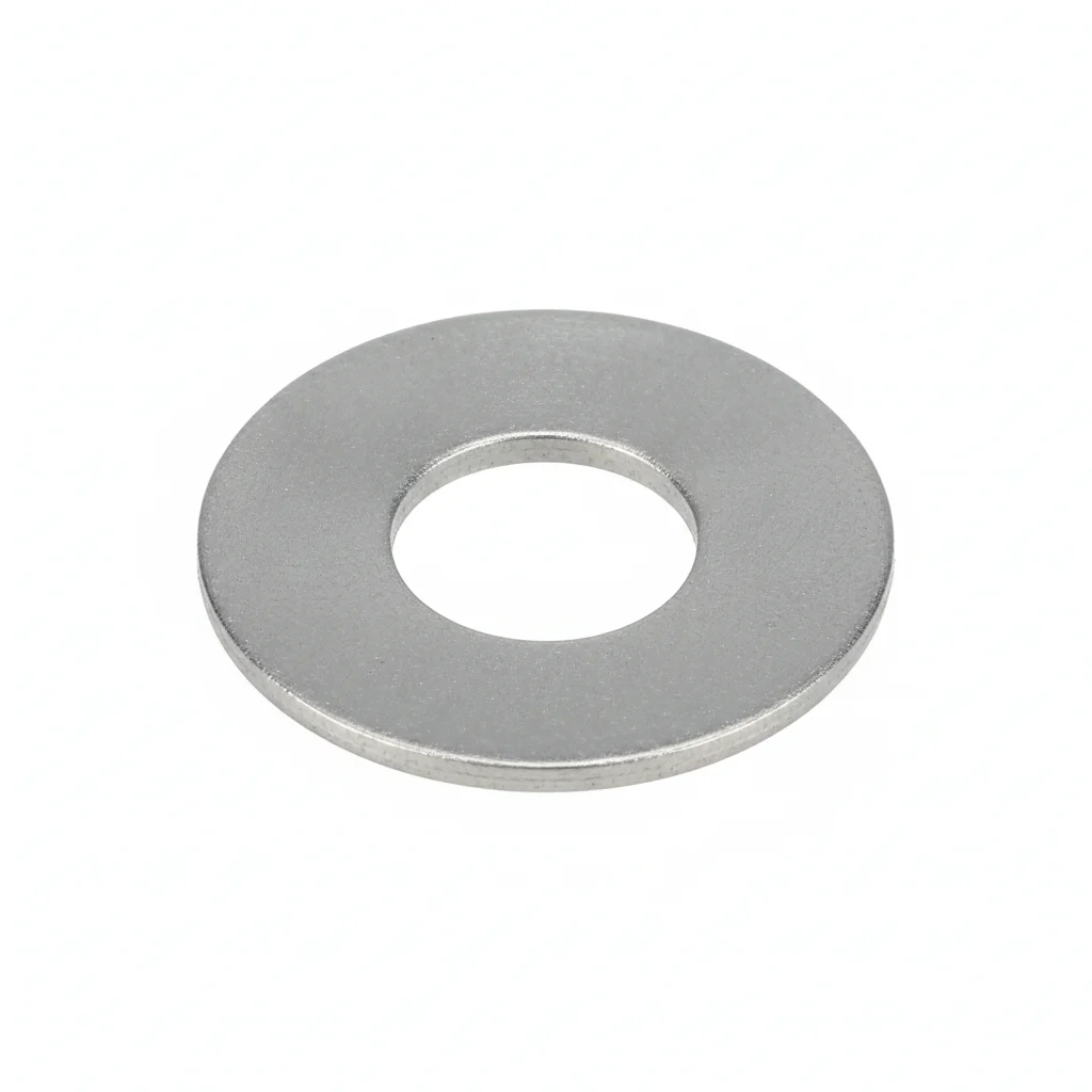
| Stockbridge Vibration Damper | Spiral Damping Line | Armor Rods | Flat Washer | Flat Washer | |
|---|---|---|---|---|---|
| SPEC | FD-1~FD-5 | Auxiliary for spans >500m | Armor Rod, per conductor type | M10-M12 | M10-M12 |
| MATERIAL | Cast Iron + Aluminum Alloy Clamp | Aluminum Alloy Spiral Wrap | Aluminum Alloy | 304 stainless steel | 304 Stainless |
| GRADE | Hot-Dip Galvanized | — | — | A2 | A2 |
| FINISH | HDG >=55um per ISO 1461 | HDG >=55um per ISO 1461 | HDG >=55um per ISO 1461 | Passivated | Passivated |
| CORROSION | C3 (ISO 12944-2) | C3 (ISO 12944-2) | C3 (ISO 12944-2) | C3 (ISO 12944-2) | C3 (ISO 12944-2) |
| TEMP | -20°C to +80°C | -20°C to +80°C | -20°C to +80°C | -20°C to +80°C | -20°C to +80°C |
| WEIGHT | ~0.5 kg/piece | ~0.5 kg/piece | ~0.5 kg/piece | ~0.005kg | ~0.005kg |
| MOQ | 100 pcs | 100 pcs | 100 pcs | 500 pcs | 500 pcs |
| PACK | VCI paper + carton | VCI paper + carton | VCI paper + carton | Plastic bag | Plastic bag |
| STD | ISO 898-1, GB/T 3098.1 | ISO 898-1, GB/T 3098.1 | ISO 898-1, GB/T 3098.1 | ISO 7089 | ISO 7089 |
| USE | LGJ 50-400 Conductor | Extra-long span lines | Conductor protection at damper location | Load distribution | Load distribution |
PROCEDURE
- Calculate damper position from the suspension clamp exit based on span and conductor type (typically 0.5–1.5m; for spans ≤300m, install one damper).
- Pre-install Armor Rods on the conductor at the clamp location to prevent fretting wear.
- Position the damper clamp over the armor rods and hand-tighten the bolts, ensuring the hammer head is horizontal (tilt ≤5°).
- Tighten clamp bolts with a calibrated torque wrench to the manufacturer's specified range (typically 40–60 Nm) to avoid over-clamping.
- Mark the conductor on both sides of the clamp with a marker pen to detect future slippage.
COMMON ERRORS
| ✕ WRONG | CONSEQUENCE | ✓ CORRECT |
|---|---|---|
| Estimating damper position by eye instead of calculating from span and conductor type. | Deviation >0.3m from the antinode can cut damping effectiveness by over 50%, leaving the conductor unprotected. | Calculate the antinode position from span length and conductor data; install at the recommended distance (0.5–1.5m) from the suspension clamp exit. |
| Tightening the damper clamp without a torque wrench (over-tightening or under-tightening). | Over-tightening embeds the clamp into the conductor strands, causing stress concentration and fatigue; under-tightening lets the damper slide, shifting it from the damping position. | Use a calibrated torque wrench set to the manufacturer's recommended range (typically 40–60 Nm) and always place Armor Rods under the clamp. |
MAINTENANCE
Seasonally, check the marker lines on each side of the clamp for any shift indicating slippage; verify clamp bolt torque remains in the 40–60 Nm range; inspect the hammer body and clamp for corrosion or damage, especially after storms, and replace any fallen damper promptly.
Plan B · Bundle Conductor Spacer + Damping
C4 Harsh per ISO 12944-2
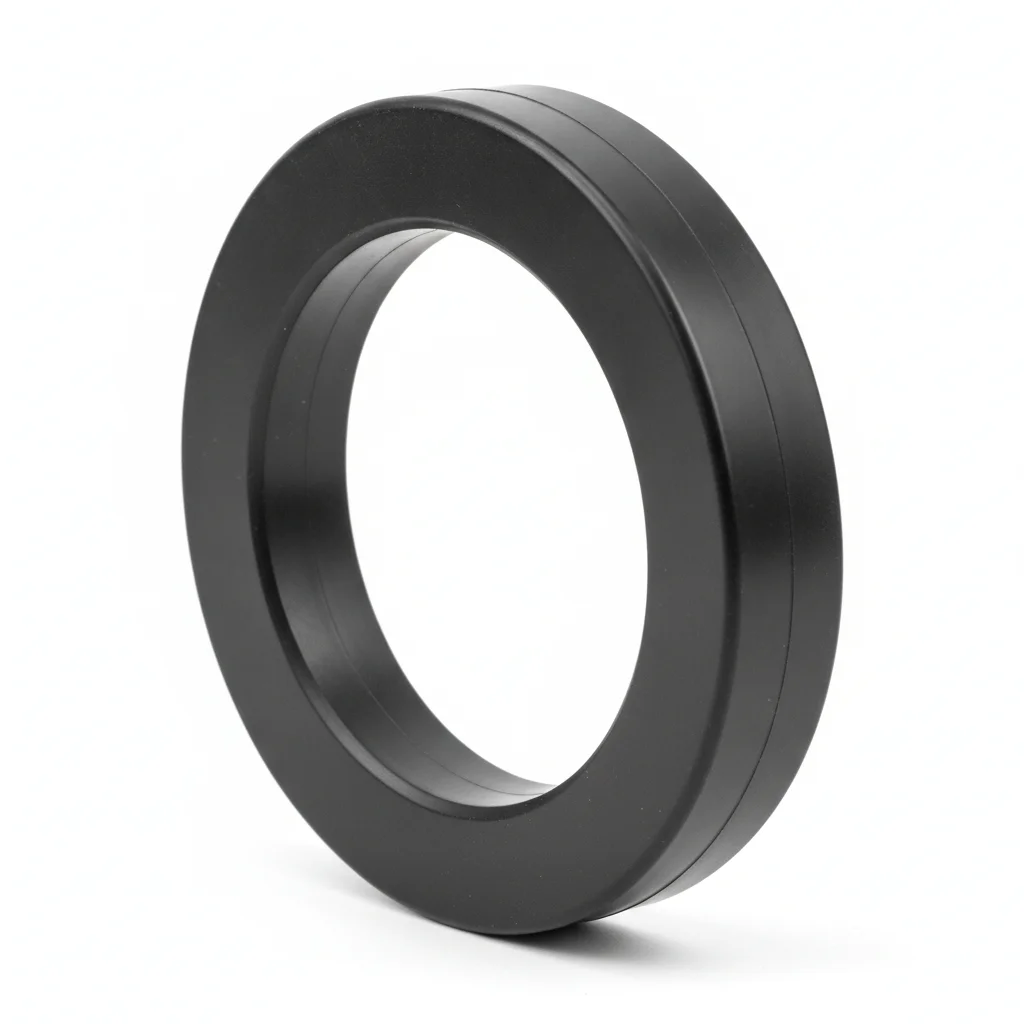
| Twin Bundle Spacer | Quad Bundle Spacer | Interphase Spacer | Flat Washer | Flat Washer | |
|---|---|---|---|---|---|
| SPEC | Type FJZ-2 | Type FJZ-4 | Customized per phase spacing | M10-M12 | M10-M12 |
| MATERIAL | Aluminum Alloy | Aluminum Alloy | FRP Core + Silicone Rubber | 304 Stainless | 304 Stainless |
| GRADE | Anodized | Anodized | Insulating | A2 | A2 |
| FINISH | HDG >=55um per ISO 1461 | HDG >=55um per ISO 1461 | HDG >=55um per ISO 1461 | Passivated | Passivated |
| CORROSION | C3 (ISO 12944-2) | C3 (ISO 12944-2) | C3 (ISO 12944-2) | C3 (ISO 12944-2) | C3 (ISO 12944-2) |
| TEMP | -20°C to +80°C | -20°C to +80°C | -20°C to +80°C | -20°C to +80°C | -20°C to +80°C |
| WEIGHT | ~0.5 kg/piece | ~0.5 kg/piece | ~0.5 kg/piece | ~0.005kg | ~0.005kg |
| MOQ | 100 pcs | 100 pcs | 100 pcs | 500 pcs | 500 pcs |
| PACK | VCI paper + carton | VCI paper + carton | VCI paper + carton | Plastic bag | Plastic bag |
| STD | ISO 898-1, GB/T 3098.1 | ISO 898-1, GB/T 3098.1 | ISO 898-1, GB/T 3098.1 | ISO 7089 | ISO 7089 |
| USE | 220kV Twin Bundle Conductor | 500kV Quad Bundle Conductor | Anti-galloping / Anti-phase-to-phase short circuit | Load distribution | Load distribution |
PROCEDURE
- Degrease spacer clamp bores and conductor contact zones with acetone; verify surface roughness Ra <3.2um.
- Position the FJZ-2 or FJZ-4 spacer on the bundle conductors, aligning the clamp jaws with the pre-marked positions from the sag table.
- Hand-tighten the M10-M12 304 stainless A2 bolts, then torque in a cross-pattern to the manufacturer's specified value (40-60 Nm) using a calibrated wrench.
- After torquing, mark each conductor adjacent to the clamp with a paint pen to detect future slippage.
- Verify spacer frame is perpendicular to the conductors and hammer dampers are horizontal (tilt ≤5°); log installation data with environmental conditions.
COMMON ERRORS
| ✕ WRONG | CONSEQUENCE | ✓ CORRECT |
|---|---|---|
| Installing the spacer without pre-installed armor rods at the clamp contact point | Fretting wear on aluminum strands leads to premature conductor fatigue and potential strand breakage at the spacer clamp. | Always fit the specified armor rods on each conductor before closing the spacer clamp to protect the strands. |
| Overtightening the clamp bolts beyond the recommended torque range | Clamp embeds into the conductor strands, creating stress concentrations that reduce fatigue life and may cause strand fracture. | Use a calibrated torque wrench set to the manufacturer's specified range (40-60 Nm) and verify with a torque audit. |
| Ignoring the required installation position tolerance relative to the antinode | A deviation exceeding 0.3m reduces damping effectiveness by over 50%, leaving the conductor unprotected against aeolian vibration. | Calculate the antinode position based on span length and conductor type; install spacers/dampers within the specified tolerance and verify with vibration measurement. |
MAINTENANCE
Inspect bundle spacers during routine line patrols at each overhaul window: check for clamp slippage (paint marks shifted), corrosion on anodized aluminum surfaces, and torque on M10-M12 bolts (40-60 Nm). After severe weather events, perform focused inspections. Replace any spacer with cracked or deformed frame immediately—do not leave the line unprotected for more than one month. Verify conductor condition at clamp edges for broken strands; if broken strands ≥10%, repair or replace the conductor section.
Plan C · Extreme Environment / Offshore Configuration
C5-M Extreme per ISO 12944-2
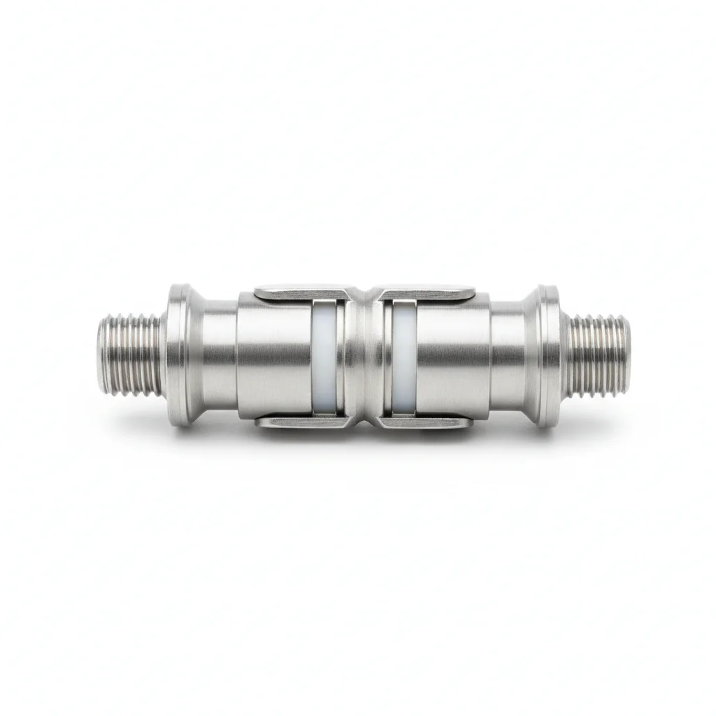
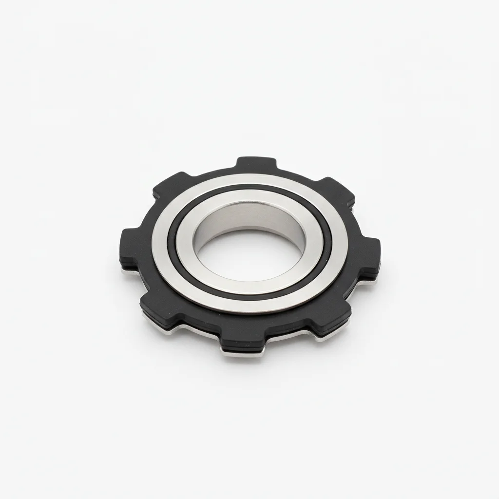
| Vibration Damper | Spacer | Damping Line | Interphase Spacer | Armor Rods | |
|---|---|---|---|---|---|
| SPEC | FD Series | Quad Bundle FJZ-4 | Customized per conductor | Per phase spacing | Per conductor type |
| MATERIAL | 316L | 316L | 316L Stainless Steel | FRP+316L | 316L |
| GRADE | A4-80 | A4-80 | A4-80 | — | A4-80 |
| FINISH | HDG >=55um per ISO 1461 | HDG >=55um per ISO 1461 | HDG >=55um per ISO 1461 | HDG >=55um per ISO 1461 | HDG >=55um per ISO 1461 |
| CORROSION | C3 (ISO 12944-2) | C3 (ISO 12944-2) | C3 (ISO 12944-2) | C3 (ISO 12944-2) | C3 (ISO 12944-2) |
| TEMP | -20°C to +80°C | -20°C to +80°C | -20°C to +80°C | -20°C to +80°C | -20°C to +80°C |
| WEIGHT | ~0.5 kg/piece | ~0.5 kg/piece | ~0.5 kg/piece | ~0.5 kg/piece | ~0.5 kg/piece |
| MOQ | 100 pcs | 100 pcs | 100 pcs | 100 pcs | 100 pcs |
| PACK | VCI paper + carton | VCI paper + carton | VCI paper + carton | VCI paper + carton | VCI paper + carton |
| STD | ISO 898-1, GB/T 3098.1 | ISO 898-1, GB/T 3098.1 | ISO 898-1, GB/T 3098.1 | ISO 898-1, GB/T 3098.1 | ISO 898-1, GB/T 3098.1 |
| USE | Offshore transmission lines | Offshore 500kV | Offshore long-span crossings | Offshore anti-galloping | C5-M conductor protection |
PROCEDURE
- Degrease all 316L stainless steel components with MEK solvent; verify surface roughness Ra <1.6um.
- Apply marine-grade anti-seize compound to all threaded connections and contact surfaces; use PTFE-encapsulated washers under bolt heads and nuts.
- Position the FD Series damper or FJZ-4 spacer on the conductor, aligning with the antinode calculation; ensure armor rods are pre-installed.
- Tighten the A4-80 fasteners to the specified torque (40-60 Nm) using a hydraulic tensioner for consistent clamp force, then verify with a torque wrench.
- Perform PMI verification on 10% of fasteners to confirm 316L grade; record results for compliance audit.
- Apply protective sealant over exposed threads and joints; attach permanent condition monitoring sensors to track vibration and corrosion.
COMMON ERRORS
| ✕ WRONG | CONSEQUENCE | ✓ CORRECT |
|---|---|---|
| Using standard galvanized fasteners instead of 316L stainless steel in the offshore C5-M environment | Galvanic corrosion between dissimilar metals accelerates deterioration, leading to fastener failure and potential conductor damage within months. | Verify that all fasteners, clamps, and spacers are 316L stainless steel (A4-80) with material certificates before installation. |
| Skipping the pre-installation of armor rods at the damper clamp location | Direct metal-to-metal contact causes fretting wear on the conductor strands, reducing fatigue life and risking strand breakage under aeolian vibration. | Always install the specified 316L armor rods between the damper clamp and the conductor to distribute clamping force and prevent abrasion. |
| Overtightening the clamp bolts beyond the recommended torque range | Excessive clamping force embeds the clamp into the conductor strands, creating stress concentrations that accelerate fatigue failure. | Use a calibrated torque wrench set to the manufacturer's specified range (40-60 Nm) and verify with a torque audit. |
MAINTENANCE
Inspect offshore vibration dampers and spacers at each scheduled maintenance window (typically during line shutdowns): check for clamp slippage using paint marks, corrosion on 316L surfaces (pay attention to weld zones and crevices), and torque on A4-80 bolts (40-60 Nm). Perform dye-penetrant testing on 10% of critical welds and clamps for crack indications. Replace any component showing pitting depth >0.3mm or corrosion affecting >5% of surface area. After major storms, conduct focused inspections and replace any missing dampers immediately—do not operate without protection for more than one month. Verify conductor condition at clamp edges for broken strands; if broken strands ≥10%, repair or replace the conductor section.
SUPPLIER CAPABILITY
Quality, Delivery & Customization
Quality Control
- ✓MTC material certificates with every batch
- ✓Key parts sampled for hardness/salt spray/torque coefficient
- ✓100% inspection or AQL sampling before shipment
Delivery
- ✓Standard parts made to order: 7-15 days
- ✓Custom parts: 25-45 days
- ✓FOB/CIF/DDP supported
Customization
- ✓Drawing review and material matching
- ✓Non-standard sizes/heads/threads
- ✓Small-batch prototyping supported
Certification
- ✓Material certificates (MTC)
- ✓Spectrographic analysis reports
- ✓Salt spray test reports (on request)
MOQ: No MOQ for standard parts; custom parts assessed by process complexity
FAQ
Frequently Asked Questions
RELATED READING
Keep Reading & Next Step
BEYOND TECHNICAL SPECS
Finding the right factory, controlling quality, delivering on time — that's the real challenge. We cover fasteners, rubber, plastics, industrial textiles. One team, end to end.
SEE CAPABILITIES →