
Nacelle Fasteners: Onshore vs Offshore Material & Coating Comparison
Nacelle internal fasteners face high-frequency vibration and salt spray. This page compares Plan A (onshore, 304 stainless steel, wedge lock) and Plan B/C (offshore, 316 stainless steel, Spiralock) based on ISO 898-1 and VDI 2230. Focus: anti-loosening, corrosion resistance, and maintenance intervals
RISK AUDIT // ENGINEERING DIAGNOSIS
Procurement Pitfall Avoidance Guide
"Nacelle fasteners fail from vibration fatigue and hidden chloride attack—here's how to avoid those failures."
QC-AUDIT // REV.5
SCALE 1:1 · 03 ITEMS
RISK-01
Fatigue Loosening of Nacelle Bolts Under Multi-Source Vibration Superposition
Corrective Measures
RISK-02
Crevice Corrosion of Nacelle Roof Bolts in Salt Spray + Condensation Water Environment
Corrective Measures
RISK-03
Mixed Fastener Specifications in Nacelle Leading to Low Maintenance Efficiency
Corrective Measures
FIELD-SPECIFIC INSIGHT
Key Differences Between Onshore and Offshore Nacelle Fastener Plans
The main engineering difference between Plan A (onshore) and Plan B/C (offshore) is the material upgrade from 304 SS to 316 SS and the anti-loosening mechanism change from wedge lock washers to Spiralock nuts. Offshore plans also specify Dacromet coating on carbon steel components. The table below highlights critical selection criteria
WHAT TO CHECK
- 1Material: 304 SS (Plan A) vs 316 SS (Plan B/C) — 316 offers higher pitting resistance equivalent to PREN >25, critical for offshore C4-C5 environments
- 2Anti-loosening: Wedge lock washers (Plan A) vs Spiralock nuts (Plan C) — Spiralock provides vibration resistance up to 5000 cycles in Junker test vs <10% preload loss for wedge lock
- 3Coating: HDG >=55µm per ISO 1461 is common to all plans; Plan C adds Dacromet on carbon steel for additional corrosion protection
- 4Life expectancy: Plan A targets 15-20 years; Plan B 20-25 years; Plan C 20-30 years, reflecting material and coating durability
| Check | Why it matters | What to specify |
|---|---|---|
| Material Grade | Corrosion resistance in salt spray environment; 316 SS withstands >100mg/m2d chloride vs 304 SS limited to C3 | Specify 316 SS (A4-70) for offshore nacelles; 304 SS (A2-70) for onshore |
| Anti-loosening Device | Prevents fatigue loosening under multi-source vibration (0.5-50Hz); wedge lock washers vs Spiralock nuts have different torque retention | Choose wedge lock washers for yaw systems; Spiralock nuts for gearbox and generator connections |
| Surface Coating | HDG provides barrier protection; Dacromet adds sacrificial protection. Offshore requires both for thread corrosion prevention | Require HDG >=55µm per ISO 1461 for all fasteners; add Dacromet for carbon steel in offshore plans |
| Maintenance Interval | Offshore access is limited by weather windows; longer intervals reduce operational cost but increase risk of undetected corrosion | — |
All data from page content. Actual performance depends on specific environmental conditions and installation torque. Verify with supplier test reports
Evidence level: source-page-only
INDUSTRY TECH REFERENCE
What Fatigue Hits First Inside the Nacelle
Fatigue inside the nacelle is not spread evenly — identify the high-risk locations first, then talk grades and materials.
80–100 m follows the KB service-height basis.
INDUSTRY TECH REFERENCE
Nacelle and In-Tower Supporting Bolts: Size, Material, Duty
Match size and material to each location for nacelle and in-tower supporting bolts — check this sheet before ordering.
| Location | Size | Material | Key parameter |
|---|---|---|---|
| Nacelle/in-tower cable-tray bolts | M6–M12 | 304/316L | Damp + vibration |
| Box-transformer cabinet/busbar bolts | M8–M16 | Hot-dip zinc/copper | Torque-coefficient report supplied |
| Lock washers (wedge type) | Flange size | Alloy steel | Consumed at every retightening |
| Offshore small parts | — | 316L/2205 | C5-M salt load; corrodes ≈5–10× faster than onshore (magnitude estimate) |
Sizes follow the industry scene-spec table (KB §7); verify against project design. The 5–10× offshore corrosion ratio is a magnitude estimate.
INDUSTRY TECH REFERENCE
How the Nut Backs Itself Out
Using the nacelle's vibration duty as an example — loosening is not gradual; transverse vibration works the nut off bite by bite.
- 1Vibration sources stack up here: wind-load cycling plus steady gearbox/drivetrain vibration — transverse vibration backs the nut off turn by turn (Junker mechanism)
- 2Each backed-off turn costs preload — the joint slides into a loose state
- 3A loose joint loads unevenly and stress amplitude climbs — cracks begin at the thread root or surface defects
- 4One crack reaches critical size and fractures brittlely, without warning (no plastic deformation at the break)
- 5Interception: wedge lock washers replace plain spring washers; run early retightening plus annual checks per the OEM manual (industry practice)
No magnitude-estimate figures in this slot; the Junker mechanism and retightening practice follow the KB.
INDUSTRY TECH REFERENCE
Assign Locking by Location — Not One Size for All
Load character differs by nacelle location — route the locking solution accordingly.
- Yaw system: rotating alternating load dominates — use wedge lock washers, not plain spring washers
- Fatigue-prone spots such as the yaw brake and main-shaft coupling: scheduled UT/MT inspection comes first — a lock washer cannot stop the crack itself
- Cabinet/busbar electrical connections: M8–M16 with a torque-coefficient report — manage preload by the torque coefficient, do not copy torque values from other locations
- Lock washers are consumed by retightening cycles (a new set each time) — reserve spares by the number of nacelle connection points
M8–M16 follows the industry scene-spec table (KB §7); verify against project design.
PLAN COMPARISON
Three-Plan Core Parameter Comparison
Compare row by row. Click column headers to jump to plan details.
| A · Plan A · Standard Onshore Unit | B · Plan B · Enhanced Offshore Unit | C · Plan C · Enhanced Offshore Unit | |
|---|---|---|---|
| 1. HEX SOCKET HEAD CAP SCREW | |||
| SPEC | M8-M16 | M8-M16 | M8×20 ~ M20×80 |
| MATERIAL | 42CrMoA | 316 Stainless Steel | 316L Stainless Steel A2-70 |
| GRADE | Grade 12.9 | A4-70 | Grade 70 |
| FINISH | HDG >=55um per ISO 1461 | HDG >=55um per ISO 1461 | HDG >=55um per ISO 1461 |
| 2. ANTI-LOOSENING WASHER | |||
| SPEC | M8-M16 | NL8-NL16 | M8 ~ M20 |
| MATERIAL | Spring Steel | 316 | Carbon Steel + Dacromet |
| GRADE | Dacromet | — | Grade 10 |
| FINISH | HDG >=55um per ISO 1461 | HDG >=55um per ISO 1461 | HDG >=55um per ISO 1461 |
| 3. NYLON INSERT LOCK NUT | |||
| SPEC | M8-M16 | M8-M16 | Accessory |
| MATERIAL | Carbon Steel | 316 | — |
| GRADE | Grade 8 | — | — |
| FINISH | HDG >=55um per ISO 1461 | HDG >=55um per ISO 1461 | HDG >=55um per ISO 1461 |
SELECTION GUIDE
Choosing the right nacelle fastener plan?
| Operating condition | Recommended option | Key basis |
|---|---|---|
| Onshore turbine nacelle, C2-C3 inland | Plan A: standard onshore — hex socket head cap screw (42CrMoA, M8-M16, Grade 12.9) + anti-loosening washer (spring steel, Dacromet) / wedge lock + Grade 8 nylon insert lock nut | C3 (ISO 12944-2); nacelle internal environment is relatively benign; 304 stainless steel meets most connection points |
| Offshore turbine nacelle, C4-C5 | Plan B: enhanced offshore — 316 stainless steel hex socket screw (M8-M16, A4-70) + wedge lock washer (316, NL8-NL16) + 316 lock nut | C4 (ISO 12944-2); 316 gives pitting resistance equivalent to PREN >25, critical for salt-laden offshore environment |
| Offshore nacelle, C5-M + special requirements (gearbox/generator vibration) | Plan C: 316L screw (M8×20~M20×80) + Spiralock lock nut (carbon steel + Dacromet, Grade 10) + inspection/maintenance tool kit | C5-M (ISO 12944-2); Spiralock nut resists vibration up to 5000 cycles in the Junker test for gearbox and generator mounts |
| Anti-loosening under multi-source vibration (gearbox 0.5-50Hz, blade 0.15-0.3Hz, 3P resonance) | Gearbox/generator mounts: Grade 10.9S bolts + wedge lock washers; main bearing housing/yaw gearbox: Grade 12.9 + double nuts; hydraulic tensioners for ±3% preload; re-tighten quarterly in year 1, then yearly | M20 Grade 10.9 fatigue limit drops to 35-40% of rated value after 10⁷ cycles; Junker: spring washer >80% preload loss after 1000 cycles, wedge lock <10% after 5000 cycles |
| Corrosion + maintenance efficiency (500-1000 bolts/nacelle, 15-20 spec types) | Use zinc-aluminum 500 coating (>2000h salt spray) or zinc-nickel alloy + sealing anti-rust wax + flange sealant; build single-unit fastener BOM and dedicated tool box; torque recheck every 3-5 years onshore / 1-2 years offshore with ultrasonic stress meter | Offshore salt spray >100mg/m²d drives crevice corrosion in 0.1-0.5mm flange gaps (Dacromet fails in 2-3 years); wrong/undersized spares waste a full tower climb of hours onshore to a day offshore |
Plan A · Standard Onshore Unit
C3 Standard per ISO 12944-2
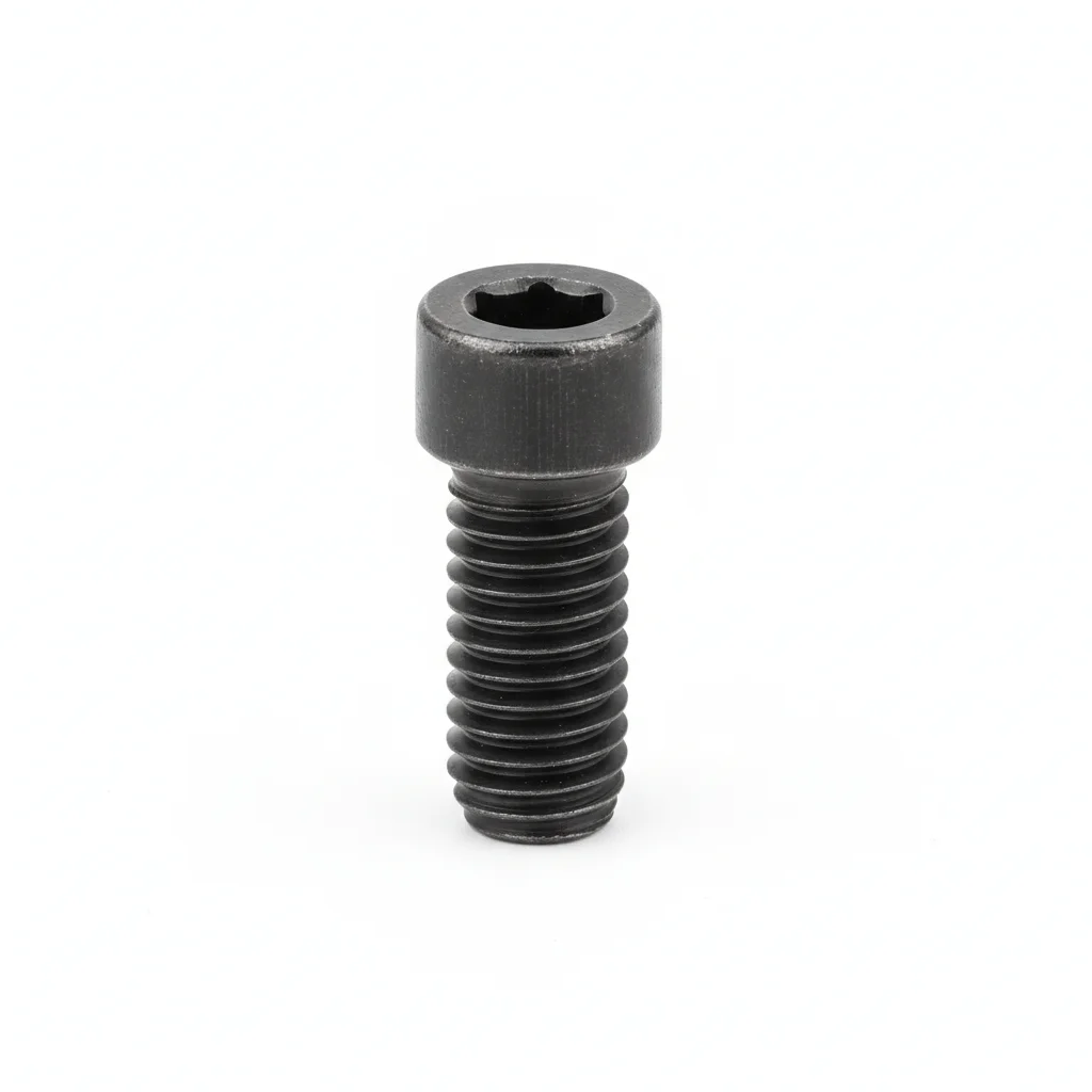
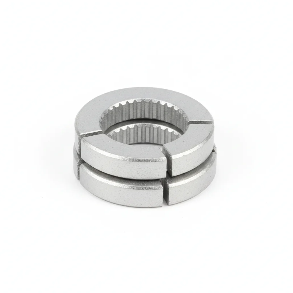
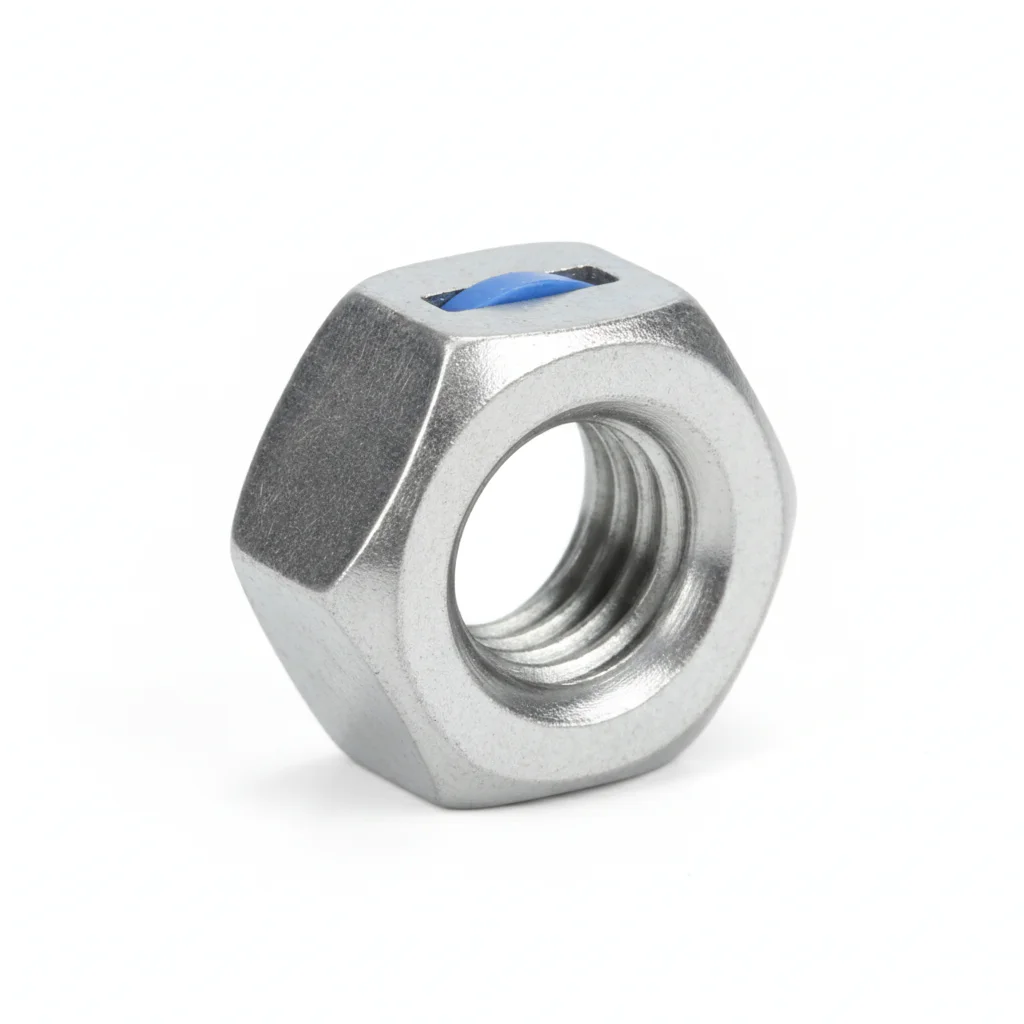
| Hex Socket Head Cap Screw | Anti-Loosening Washer | Nylon Insert Lock Nut | |
|---|---|---|---|
| SPEC | M8-M16 | M8-M16 | M8-M16 |
| MATERIAL | 42CrMoA | Spring Steel | Carbon Steel |
| GRADE | Grade 12.9 | Dacromet | Grade 8 |
| FINISH | HDG >=55um per ISO 1461 | HDG >=55um per ISO 1461 | HDG >=55um per ISO 1461 |
| CORROSION | C3 (ISO 12944-2) | C3 (ISO 12944-2) | C3 (ISO 12944-2) |
| TEMP | -20°C to +80°C | -20°C to +80°C | -20°C to +80°C |
| WEIGHT | ~0.5 kg/piece | ~0.5 kg/piece | ~0.5 kg/piece |
| MOQ | 100 pcs | 100 pcs | 100 pcs |
| PACK | VCI paper + carton | VCI paper + carton | VCI paper + carton |
| STD | ISO 898-1, GB/T 3098.1 | ISO 898-1, GB/T 3098.1 | ISO 898-1, GB/T 3098.1 |
| USE | Nacelle structural connection | Wedge lock washer / Disc spring | Used with anti-loosening washer |
PROCEDURE
- Degrease mating surfaces with isopropyl alcohol and confirm flatness to 0.1 mm per 100 mm before assembly.
- Position the 304 SS hex socket head cap screw with the anti-loosening washer under the head, then thread the nylon insert lock nut by hand until snug.
- Tighten in a star pattern using a calibrated torque wrench, applying the torque value specified in the plan's QA log, and record each bolt's final torque.
- Verify seating of all fasteners; on a 5% sample, check joint gap with a feeler gauge to confirm no relaxation has occurred.
- Mark each tightened fastener with torque seal paint and capture three-angle photos for the QA documentation package.
COMMON ERRORS
| ✕ WRONG | CONSEQUENCE | ✓ CORRECT |
|---|---|---|
| Substituting a lower strength grade for the specified 12.9 socket head cap screw | The bolt yields under vibration loads, leading to early loosening and potential joint separation in the nacelle structure. | Confirm the grade marking matches ISO 898-1 Grade 12.9 before installation and use a calibrated torque wrench with ±3% accuracy. |
| Installing the anti-loosening washer upside down or on the nut side instead of under the bolt head | The wedge locking action is lost, allowing vibration to back off the nut within the first operating season. | Place the wedge lock washer directly under the bolt head with the serrations facing the joint surface, per the plan's assembly drawing. |
MAINTENANCE
Inspect nacelle fasteners at each scheduled overhaul window; re-torque any bolt found below 80% of its specified torque. Replace fasteners showing corrosion over 5% of surface area or pitting deeper than 0.3 mm. Perform a full disassembly inspection on a 20% sample at the 3-year mark and replace all critical fasteners at the 5-year interval, documenting results in CMMS.
Plan B · Enhanced Offshore Unit
C4 Harsh per ISO 12944-2
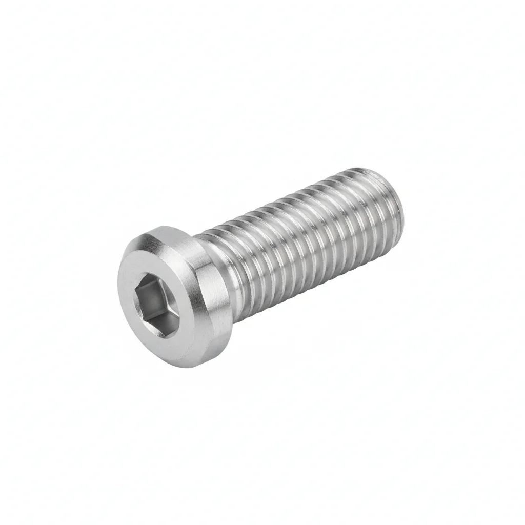
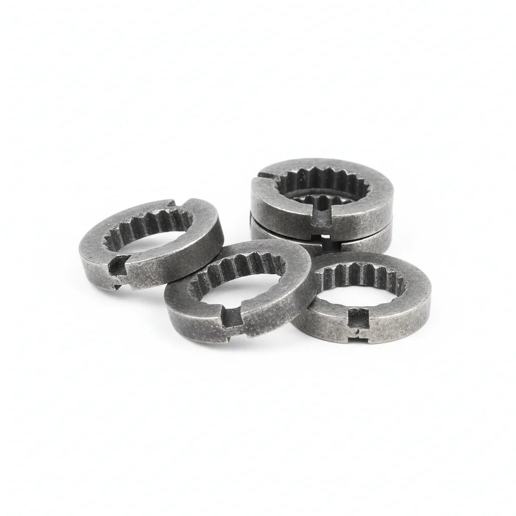
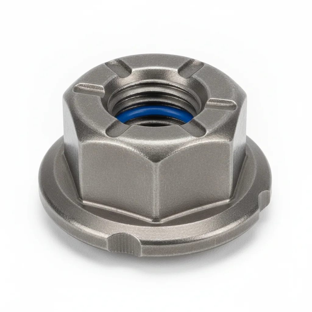
| Hex Socket Head Cap Screw | Wedge Lock Washer | Lock Nut | |
|---|---|---|---|
| SPEC | M8-M16 | NL8-NL16 | M8-M16 |
| MATERIAL | 316 Stainless Steel | 316 | 316 |
| GRADE | A4-70 | — | — |
| FINISH | HDG >=55um per ISO 1461 | HDG >=55um per ISO 1461 | HDG >=55um per ISO 1461 |
| CORROSION | C3 (ISO 12944-2) | C3 (ISO 12944-2) | C3 (ISO 12944-2) |
| TEMP | -20°C to +80°C | -20°C to +80°C | -20°C to +80°C |
| WEIGHT | ~0.5 kg/piece | ~0.5 kg/piece | ~0.5 kg/piece |
| MOQ | 100 pcs | 100 pcs | 100 pcs |
| PACK | VCI paper + carton | VCI paper + carton | VCI paper + carton |
| STD | ISO 898-1, GB/T 3098.1 | ISO 898-1, GB/T 3098.1 | ISO 898-1, GB/T 3098.1 |
| USE | High corrosion areas | Offshore nacelle anti-loosening | Used with 316 bolts |
PROCEDURE
- Degrease the 316 stainless steel bolt and wedge lock washer contact faces with acetone, then confirm surface roughness Ra below 3.2 μm.
- Apply a salt-spray-resistant joint compound formulated for -20°C to +80°C service; seat the wedge lock washer with its serrations engaging both the bolt head and the mating flange.
- Align the 316 A4-70 socket head cap screw within 0.5 mm, then tighten in a cross-pattern sequence to the torque specified for the M8–M16 size; log ambient humidity and temperature with each value.
- Pull-test a 5% random sample to 80% of proof load and replace any fastener that slips below the acceptance threshold.
- Coat the exposed thread ends and washer periphery with a weatherproof sealant and attach corrosion monitoring coupons beside critical joints.
COMMON ERRORS
| ✕ WRONG | CONSEQUENCE | ✓ CORRECT |
|---|---|---|
| Mixing 304 stainless steel bolts with 316 washers in the same offshore joint | Galvanic potential difference accelerates crevice attack at the thread interface, leading to pitting within the salt-laden C4–C5 atmosphere. | Keep the complete fastener set in 316 stainless steel (A4-70) — bolt, wedge lock washer, and nut — to avoid dissimilar-metal corrosion. |
| Tightening wedge lock washers in a single pass without cross-pattern sequencing | Uneven preload lets the wedge faces slip under yaw and gearbox vibration, so the joint loosens well before the 20–25 year design life. | Use a calibrated wrench and follow a star-pattern sequence, then verify torque retention with a 10% sample check. |
MAINTENANCE
At each scheduled overhaul window, inspect 316 wedge lock washers for crevice staining and measure residual torque; replace any fastener showing pitting depth beyond 0.3 mm or corrosion covering more than 5% of the surface. Because offshore access is limited, schedule a full disassembly and 20% sample inspection every 3 years, and replace all critical 316 fasteners every 5 years regardless of apparent condition.
Plan C · Enhanced Offshore Unit
C5-M Extreme per ISO 12944-2
| Hex Socket Head Cap Screw | Spiralock Lock Nut | Inspection & Maintenance Tool Kit | |
|---|---|---|---|
| SPEC | M8×20 ~ M20×80 | M8 ~ M20 | Accessory |
| MATERIAL | 316L Stainless Steel A2-70 | Carbon Steel + Dacromet | — |
| GRADE | Grade 70 | Grade 10 | — |
| FINISH | HDG >=55um per ISO 1461 | HDG >=55um per ISO 1461 | HDG >=55um per ISO 1461 |
| CORROSION | C3 (ISO 12944-2) | C3 (ISO 12944-2) | C3 (ISO 12944-2) |
| TEMP | -20°C to +80°C | -20°C to +80°C | -20°C to +80°C |
| WEIGHT | ~0.5 kg/piece | ~0.5 kg/piece | ~0.5 kg/piece |
| MOQ | 100 pcs | 100 pcs | 100 pcs |
| PACK | VCI paper + carton | VCI paper + carton | VCI paper + carton |
| STD | ISO 898-1, GB/T 3098.1 | ISO 898-1, GB/T 3098.1 | ISO 898-1, GB/T 3098.1 |
| USE | Nacelle structural connection | Vibration node anti-loosening | Periodic torque verification |
PROCEDURE
- Degrease the 316L stainless steel bolt and Spiralock nut threads with MEK, then verify surface roughness Ra stays below 1.6 μm.
- Brush a marine-grade anti-corrosion compound rated for -50°C to +200°C onto the threads and under the head; use PTFE-encapsulated washers to isolate the Dacromet-coated carbon steel nut from the 316L bolt.
- Align the M8×20–M20×80 bolt within 0.3 mm, then tension with a hydraulic tensioner to the specified preload; perform PMI verification on a 10% sample and record results for the compliance audit.
- Dye-penetrant test a 10% sample of the installed Spiralock assemblies; replace any fastener showing crack indications before energizing the turbine.
- Seal the exposed fastener heads and nut faces with a moisture-curing protective sealant, then install permanent condition-monitoring instrumentation on the highest-vibration nodes.
COMMON ERRORS
| ✕ WRONG | CONSEQUENCE | ✓ CORRECT |
|---|---|---|
| Using a standard hex nut instead of the Spiralock lock nut on gearbox mounting bolts | The 50 Hz generator and gearbox meshing vibration causes the thread flank to disengage, producing rapid preload loss and fatigue failure of the 316L bolt. | Always pair the 316L socket head cap screw with the Spiralock lock nut — its wedge-ramp thread design prevents transverse loosening under multi-source vibration. |
| Applying the Dacromet-coated carbon steel Spiralock nut directly against bare 316L threads without a PTFE washer | The carbon steel and stainless steel couple creates galvanic corrosion in the C5-M salt spray, thinning the Dacromet coating and seizing the threads. | Install a PTFE-encapsulated washer between the nut and the joint surface, and coat the threads with the marine-grade compound before assembly. |
MAINTENANCE
During each scheduled inspection window, use the supplied Inspection & Maintenance Tool Kit to verify residual preload on Spiralock assemblies; replace any fastener with pitting depth over 0.3 mm or corrosion affecting more than 5% of the surface. Given the 20–30 year design life, plan a full disassembly and 20% sample NDT every 3 years, and swap out all critical fasteners every 5 years, documenting every action in the CMMS with inspector ID and corrective notes.
SPEC MATRIX
Product Specifications Covered for This Scenario
Specifications from the Yaxiio product catalog. Weights are theoretical calculated values.
| DIA | LENGTH | MATERIAL | GRADE | FINISH | SKU | UNIT WEIGHT |
|---|---|---|---|---|---|---|
| M12 | 30, 35, 40, 45, 50, 60, 70, 80 | Alloy Steel | 10.9S | Black Oxide | 8 | 42–86 g |
| M16 | 40–120 (10 sizes) | Alloy Steel | 10.9S | Black Oxide | 10 | 98–220 g |
| M20 | 45–160 (11 sizes) | Alloy Steel | 10.9S | Black Oxide | 11 | 180–460 g |
| M24 | 50–200 (12 sizes) | Alloy Steel | 10.9S | Black Oxide | 12 | 300–830 g |
| M30 | 60–240 (12 sizes) | Alloy Steel | 10.9S | Black Oxide | 12 | 570–1500 g |
REFERENCED STANDARDS
Technical Basis & Reference Standards
SUPPLIER CAPABILITY
Quality, Delivery & Customization
Quality Control
- ✓MTC material certificates with every batch
- ✓Key parts sampled for hardness/salt spray/torque coefficient
- ✓100% inspection or AQL sampling before shipment
Delivery
- ✓Standard parts made to order: 7-15 days
- ✓Custom parts: 25-45 days
- ✓FOB/CIF/DDP supported
Customization
- ✓Drawing review and material matching
- ✓Non-standard sizes/heads/threads
- ✓Small-batch prototyping supported
Certification
- ✓Material certificates (MTC)
- ✓Spectrographic analysis reports
- ✓Salt spray test reports (on request)
MOQ: No MOQ for standard parts; custom parts assessed by process complexity
FAQ
Frequently Asked Questions
BEYOND TECHNICAL SPECS
Finding the right factory, controlling quality, delivering on time — that's the real challenge. We cover fasteners, rubber, plastics, industrial textiles. One team, end to end.
SEE CAPABILITIES →