Pipe Support and Expansion Joint Fastener Failures: Thermal Expansion Risks
When a high-temperature steam pipe rises to 400°C, it expands approximately 5mm per meter. If anchor support U-bolts loosen, the pipe loses directional restraint, pushing expansion joints beyond compensation range and causing bellows rupture. If expansion joint shipping tie rods are not removed after installation, the joint locks, transferring all thermal stress to elbows—welds crack on first temperature rise. This page compares fastener solutions for medium/low pressure (Grade 10.9 U-bolt) and high temperature/high pressure (spring hanger + 316L limit tie rod) to control thermal expansion
RISK AUDIT // ENGINEERING DIAGNOSIS
Procurement Pitfall Guide
"On the plant floor, loose anchor bolts and forgotten tie rods are the quiet culprits behind ruptured bellows and cracked welds."
QC-AUDIT // REV.5
SCALE 1:1 · 03 ITEMS
RISK-01
Loose Anchor Support Bolts Cause Loss of Control Over Pipe Thermal Expansion Direction
Corrective Measures
RISK-02
Failure to Remove Expansion Joint Shipping Tie Rods Leads to Thermal Stress Cracking in Pipes
Corrective Measures
RISK-03
Incorrect Spring Selection for Spring Hanger Support Causes Pipe Sagging
Corrective Measures
FIELD-SPECIFIC INSIGHT
Thermal Expansion Failure Chain: What to Check in Pipe Support Fasteners
The most overlooked failure in industrial piping is not the pipe itself but the fasteners that control thermal expansion. Two critical risks: (1) anchor support bolts loosening, allowing uncontrolled expansion that ruptures bellows; (2) expansion joint shipping tie rods left installed, locking the joint and forcing all thermal stress onto elbows. Both lead to weld cracking and unplanned shutdowns
WHAT TO CHECK
- 1Anchor support U-bolts: Grade 10.9 + double nuts + welded anti-loosening stops required; quarterly torque inspection to prevent loosening
- 2Expansion joint shipping tie rods: Must be removed after installation; yellow warning color and 'Remove After Installation' tag are mandatory
- 3Spring hanger support: Spring stiffness must match pipe thermal displacement calculation per ASME B31.3; incorrect selection causes sagging or over-constraint
- 4Corrosion protection: HDG >=55µm per ISO 1461 for C3/C4 environments; inspect for pitting depth or surface corrosion exceeding thresholds
| Check | Why it matters | What to specify |
|---|---|---|
| Anchor bolt torque | Loose bolts → anchor point fails → thermal expansion uncontrolled → bellows rupture | Grade 10.9 U-bolt, double nut, welded stop; quarterly re-torque if below 80% specified torque |
| Shipping tie rod removal | Tie rod left installed → expansion joint locked → all thermal stress on elbows → weld crack on first heat-up | Yellow tie rod with 'Remove After Installation' tag; verify removal in commissioning checklist |
| Spring hanger selection | Wrong stiffness → pipe deviates in hot state → additional bending moment on elbows → fatigue cracking | Spring selection per pipe thermal displacement calculation; ASME B31.3 compliance |
| Corrosion condition | Corrosion reduces fastener strength; surface corrosion or pitting depth beyond thresholds requires replacement | HDG >=55µm per ISO 1461; inspect every 6 months; replace if threshold exceeded |
Data based on ASME B31.3 and EJMA standards. Actual thermal expansion values depend on pipe material, temperature, and length—verify per project calculation
Evidence level: standard-backed
INDUSTRY TECH REFERENCE
The Thermal-Expansion Ledger: The First Number Before Any Hanger Layout
Every hanger selection and retightening decision on a hot steam line starts from one number set—the thermal-expansion budget. Total it first, then divide the work among anchors, guides, and spring supports.
- The budget comes first: carbon steel averages about 6.9 mm/m of linear growth over the 21→500°C span, so 100 m of straight pipe adds up to roughly 690 mm (ASME B31.3 Table C-1)—hanger layout and spring class both start from this number
- Divide and guide: anchor supports cut the line into independent thermal-expansion sections, guide supports restrain lateral movement and leave room for axial slide—the job of a support is to give thermal growth a direction, not to pin the pipe down
- Thermal-cycling duty: on lines that see frequent start-stop or temperature swings, joint stresses swing back and forth—for such pipe racks, support-bolt retightening belongs in controlled assembly; GC1/severe-cycling service mandates maximum bolt installation load control (TSG 31-2025, procedure per GB/T 20801 and GB/T 32270), not a torque-by-feel maintenance visit
No order-of-magnitude estimates are used in this slot.
INDUSTRY TECH REFERENCE
Lost Direction Control: From U-Bolt Preload Loss to a Cracked Weld
Once a U-bolt loosens, the pipe's thermal growth has no direction left—the 690 mm of movement in the budget will find its own path, into the expansion joint or into an elbow. Every link in this chain has a checkpoint.
- 1Cyclic loading: on lines with frequent start-stop or temperature swings, the U-bolt and the pipe grow at different rates, so joint stresses swing back and forth each cycle—preload starts leaking away through repeated unload-reload
- 2Constraint decay: preload erodes step by step and the U-bolt's friction grip on the pipe weakens with it—support sliding friction drifts below the pipe's thermal push
- 3Direction is lost: with insufficient restraint the pipe moves the weak way—the ~690 mm of growth over 100 m of straight pipe no longer follows its intended path
- 4Into the weak spot: the movement pours into the expansion joint (over-extended or over-compressed; locked solid if a shipping tie rod was left in) or into an elbow—stress concentration lands on the weld
- 5The endpoint and the back-check: the elbow weld cracks in fatigue and the line stops for repair—check the support and the U-bolt first, before deciding whether to touch the flange bolts
No order-of-magnitude estimates are used in this slot.
INDUSTRY TECH REFERENCE
Spring Supports and Their Hardware: Selection and Acceptance
A spring hanger picked wrong, a clamp bolt rusted through, a locking pin left in—the next step after a sagging pipe is a flange pulled off-square. Spec and accept the hardware against these four lines.
| Component | Selection basis | Acceptance gate |
|---|---|---|
| Variable-spring support | Small-to-medium travel; the ≤25% load-variation cap is the MSS SP-58 default | Verify cold-to-hot travel and set load on the nameplate against the design (GB/T 17116.1~.3-2018 clause 6.15) |
| Constant-spring support | Large-travel duty (high-temperature steam and similar big thermal growth) | As above; inspect the travel indicator against its set range |
| Clamp bolt / hanger rod nut / turnbuckle | Carbon/alloy steel hardware (anchor, guide, and spring supports) | Four inspection gates: corrosion fracture, compression relaxation/setting, travel hard-top or hard-bottom, transport locking pin left in |
| Load-travel calculation | Cold-to-hot load variation decides the spring class (GB/T 17116.1~.3 series) | Calibrate before installation, re-check the nameplate after; fix the support first, then touch the flange bolts |
No order-of-magnitude estimates are used in this slot.
INDUSTRY TECH REFERENCE
Standards for Pipe Supports and Hot Lines: Which Ones to Cite
Support selection, thermal-expansion calculation, and the regulatory gate each answer to its own document—these six are the ones most often raised at RFQ and acceptance.
The standards listed in this slot — MSS SP-58-2025, GB/T 17116.1~.3-2018, ASME B31.3-2024, TSG 31-2025, GB/T 20801 (.1/.5-2025), and GB 50316-2000 (2008 edition) — are all public standards; only the standard numbers and scope of application are given for procurement navigation, while acceptance values are governed by the current editions of the standards. No order-of-magnitude estimates are used in this slot.
PLAN COMPARISON
Three-Plan Core Parameter Comparison
Compare row by row. Click column headers to jump to plan details.
| A · A · Medium/Low Pressure Piping | B · B · High Temperature/High Pressure Piping | C · Plan C · High Pressure/Ultra-High Pressure | |
|---|---|---|---|
| 1. U-BOLT FOR PIPE CLAMP | |||
| SPEC | M12-M20 | Select by Load | Select by Load |
| MATERIAL | 42CrMo | 304 + 60Si2Mn Spring Steel | 316L + 60Si2Mn Spring Steel |
| GRADE | Grade 10.9 Dacromet | — | — |
| FINISH | HDG >=55um per ISO 1461 | HDG >=55um per ISO 1461 | HDG >=55um per ISO 1461 |
| 2. EXPANSION JOINT SHIPPING TIE ROD (YELLOW) | |||
| SPEC | M12-M20 | M16-M24 | M16-M24 |
| MATERIAL | Carbon Steel | 316L | 316L |
| FINISH | HDG >=55um per ISO 1461 | HDG >=55um per ISO 1461 | HDG >=55um per ISO 1461 |
A · Medium/Low Pressure Piping
C3 Standard per ISO 12944-2
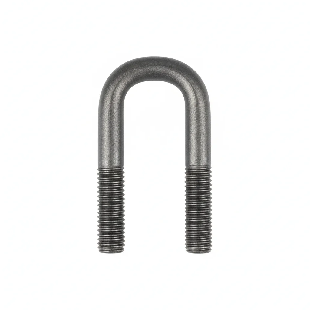
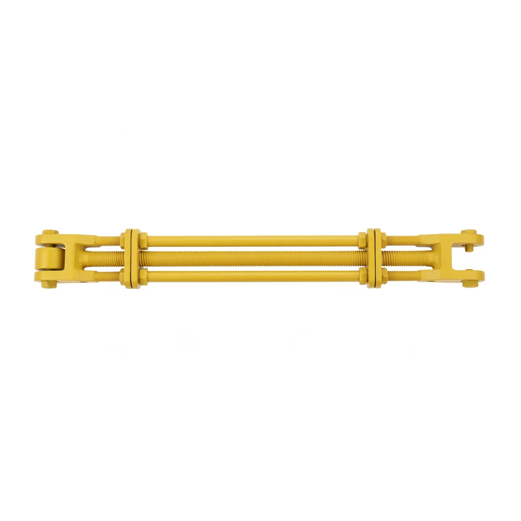
| U-Bolt for Pipe Clamp | Expansion Joint Shipping Tie Rod (Yellow) | |
|---|---|---|
| SPEC | M12-M20 | M12-M20 |
| MATERIAL | 42CrMo | Carbon Steel |
| GRADE | Grade 10.9 Dacromet | — |
| FINISH | HDG >=55um per ISO 1461 | HDG >=55um per ISO 1461 |
| CORROSION | C3 (ISO 12944-2) | C3 (ISO 12944-2) |
| TEMP | -20°C to +80°C | -20°C to +80°C |
| WEIGHT | ~0.5 kg/piece | ~0.5 kg/piece |
| MOQ | 100 pcs | 100 pcs |
| PACK | VCI paper + carton | VCI paper + carton |
| STD | ISO 898-1, GB/T 3098.1 | ISO 898-1, GB/T 3098.1 |
| USE | Anchor/Guide Supports | Transport Fixation (Remove After Installation) |
PROCEDURE
- Clean the pipe surface at the anchor point and remove any debris or moisture that could compromise the liner contact.
- Place a 3mm thick stainless steel liner between the pipe and the U-bolt to protect the anti-corrosion coating.
- Position the Grade 10.9 U-bolt around the pipe and through the support structure; align the bolt legs evenly.
- Thread on the first nut and tighten to a snug fit, then add the second nut as a lock nut and tighten against the first.
- Weld anti-loosening stops on the nut flats to prevent rotation; verify the U-bolt does not indent the liner.
- Mark the nuts with torque seal paint and record the installation date on the inspection tag.
COMMON ERRORS
| ✕ WRONG | CONSEQUENCE | ✓ CORRECT |
|---|---|---|
| Installing the U-bolt without the stainless steel liner | The U-bolt chafes the pipe's anti-corrosion coating, leading to localized corrosion and eventual weakening of the pipe wall at the anchor point. | Always insert a 3mm stainless steel liner between the U-bolt and the pipe to protect the coating. |
| Using a single nut instead of double nuts on the U-bolt | Vibration and thermal cycling cause the single nut to loosen, allowing the anchor point to fail and the pipe to move uncontrollably during expansion. | Secure the U-bolt with double nuts, with the second nut torqued against the first to lock it in place. |
MAINTENANCE
Inspect anchor support U-bolts quarterly for any signs of nut rotation or loosening; re-torque if the nuts have moved from their original marked position. Confirm the liner remains intact and the pipe coating is not damaged.
B · High Temperature/High Pressure Piping
C4 Harsh per ISO 12944-2
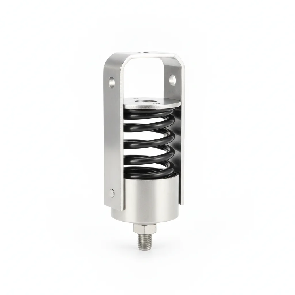
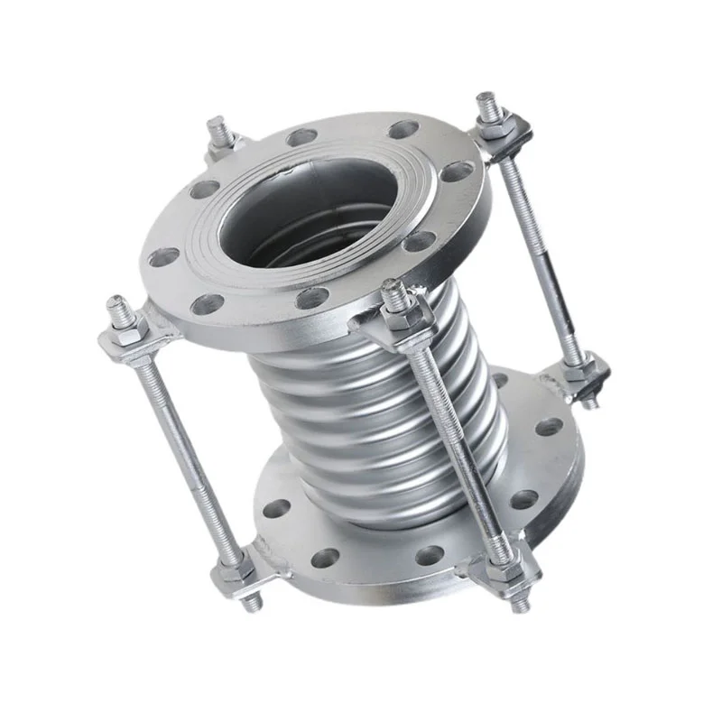
| Spring Hanger Support | Expansion Joint Limit Tie Rod | |
|---|---|---|
| SPEC | Select by Load | M16-M24 |
| MATERIAL | 304 + 60Si2Mn Spring Steel | 316L |
| GRADE | — | — |
| FINISH | HDG >=55um per ISO 1461 | HDG >=55um per ISO 1461 |
| CORROSION | C3 (ISO 12944-2) | C3 (ISO 12944-2) |
| TEMP | -20°C to +80°C | -20°C to +80°C |
| WEIGHT | ~0.5 kg/piece | ~0.5 kg/piece |
| MOQ | 100 pcs | 100 pcs |
| PACK | VCI paper + carton | VCI paper + carton |
| STD | ISO 898-1, GB/T 3098.1 | ISO 898-1, GB/T 3098.1 |
| USE | Elastic Support for High-Temp Pipes | Limit Stop for High-Temp Bellows Expansion Joint |
PROCEDURE
- Degrease the pipe contact area and spring hanger base with acetone; verify surface roughness Ra below 3.2 μm using a profilometer.
- Apply a joint compound rated for the service temperature range of -20°C to +80°C (as per product data) to the 316L limit tie rod threads and bearing surfaces.
- Position the spring hanger support so the pipe rests at its design elevation; align the 316L limit tie rod within the expansion joint lug holes without forcing.
- Tighten the M16–M24 316L limit tie rod nuts in a cross-pattern sequence to the torque specified in the pipe stress report; then back off the adjustment nut to the marked travel limit per the EJMA design.
- Lock the limit tie rod nuts with the integral locking feature (or jam nut) and paint a witness mark across the nut and rod; verify the spring hanger's travel indicator shows free movement within the calculated range.
COMMON ERRORS
| ✕ WRONG | CONSEQUENCE | ✓ CORRECT |
|---|---|---|
| Leaving the yellow shipping tie rods in place on the expansion joint after installation | The bellows cannot expand, forcing all thermal expansion stress onto the pipe elbows, which can crack the welds on the first heat-up as described in the scenario. | Remove all yellow shipping tie rods after installation per the 'Remove After Installation' tag; store them for future transport and confirm removal in the commissioning checklist. |
| Setting the 316L limit tie rod nut gap too tight or too loose | An overly tight setting restricts the bellows' designed movement, while an overly loose setting fails to limit over-expansion, both risking bellows rupture or pipe support overload. | Adjust each limit tie rod nut to the position marked in the pipe stress report, then lock it and do not adjust again during operation; verify the gap with a feeler gauge against the design value. |
| Selecting a spring hanger with incorrect stiffness for the pipe's thermal displacement | A too-stiff spring restricts expansion, while a too-soft one allows sagging, deviating the pipe from design elevation by more than 10mm in the hot state and causing weld fatigue. | Have the spring hanger selected by a pipe stress engineer based on ASME B31.3 thermal displacement calculations; verify the spring's free height and load rating match the specification before installation. |
MAINTENANCE
Inspect the spring hanger and limit tie rods at each overhaul window or seasonal shutdown: check that the 316L tie rod nuts show no rotation from the witness mark, confirm the spring hanger's travel indicator remains within the design range, and look for corrosion or pitting on the 316L rod surfaces. If permanent spring deformation exceeds 5% of free height, replace the spring after unloading the pipe. Re-torque any tie rod nut that has moved, using the original torque specification.
Plan C · High Pressure/Ultra-High Pressure
C5-M Extreme per ISO 12944-2
| Spring Hanger Support | Expansion Joint Limit Tie Rod | |
|---|---|---|
| SPEC | Select by Load | M16-M24 |
| MATERIAL | 316L + 60Si2Mn Spring Steel | 316L |
| GRADE | — | — |
| FINISH | HDG >=55um per ISO 1461 | HDG >=55um per ISO 1461 |
| CORROSION | C3 (ISO 12944-2) | C3 (ISO 12944-2) |
| TEMP | -20°C to +80°C | -20°C to +80°C |
| WEIGHT | ~0.5 kg/piece | ~0.5 kg/piece |
| MOQ | 100 pcs | 100 pcs |
| PACK | VCI paper + carton | VCI paper + carton |
| STD | ISO 898-1, GB/T 3098.1 | ISO 898-1, GB/T 3098.1 |
| USE | Extreme Conditions / Maximum Protection | Extreme Conditions / Maximum Protection |
PROCEDURE
- Degrease all mating surfaces with MEK solvent; verify surface roughness Ra below 1.6 μm using a profilometer to ensure proper seating of the 316L components.
- Apply a marine-grade anti-corrosion compound rated for the service temperature range of -20°C to +80°C to the 316L limit tie rod threads and spring hanger contact points.
- Install the spring hanger support (316L + 60Si2Mn spring steel) so the pipe is at design elevation; position the M16–M24 316L limit tie rods through the expansion joint lugs, aligning within 0.3mm as per the EJMA design.
- Tighten the tie rod nuts using a hydraulic tensioner to the preload specified in the pipe stress report; perform PMI verification on 10% of the fasteners to confirm 316L grade and document for compliance audit.
- Conduct dye penetrant NDT on 10% of the installed tie rod welds and adjacent areas; replace any fastener showing crack indications.
- Apply a protective sealant over all exposed 316L threads and nuts, then install permanent condition monitoring instrumentation (e.g., strain gauges) on the critical tie rods; file the compliance report with the regulatory authority.
COMMON ERRORS
| ✕ WRONG | CONSEQUENCE | ✓ CORRECT |
|---|---|---|
| Using the yellow shipping tie rods as permanent limit tie rods | Shipping rods are sized only for transport loads, not for thermal expansion restraint; they can fail under high-pressure service, releasing the bellows and causing uncontrolled pipe movement. | Always use the designated 316L limit tie rods (M16–M24) for permanent installation; remove and discard or store the yellow shipping rods after commissioning. |
| Tightening the 316L limit tie rod nuts without hydraulic tensioning or torque control | Inconsistent preload can lead to uneven load distribution on the expansion joint, causing bellows distortion or premature fatigue under high-pressure cycling. | Use a calibrated hydraulic tensioner or torque wrench with a certificate of accuracy; tighten to the preload value from the pipe stress report and verify with the tensioner's pressure gauge. |
| Skipping the dye penetrant NDT on tie rod welds and attachments | Undetected cracks in welds or base material can propagate under thermal cycling, leading to sudden tie rod failure and potential pipe rupture in high-pressure systems. | Perform dye penetrant inspection on 10% of the tie rod welds and critical attachments after installation; replace any component showing crack indications before commissioning. |
MAINTENANCE
At each scheduled outage or seasonal inspection, verify the 316L limit tie rod nuts remain locked (witness marks intact) and check for any signs of corrosion or pitting on the 316L surfaces, especially in the thread area. Monitor the spring hanger's travel indicator and compare to the design range; if the spring's free height has shortened by more than 5%, replace it after unloading the pipe. Perform dye penetrant spot checks on the tie rod welds every major overhaul, and re-torque any nut that has loosened using the original preload specification.
SELECTION GUIDE
Selecting the Right Thermal Expansion Control
| Operating condition | Recommended option | Key basis |
|---|---|---|
| Medium/low-pressure piping | Plan A — Grade 10.9 U-bolts for anchor/guide supports (42CrMo, M12-M20, Dacromet) + yellow shipping tie rods (carbon steel, M12-M20) for transport only | MSS SP-58 pipe hangers and supports; GB/T 17116 pipe supports and hangers |
| High-temperature / high-pressure piping (thermal expansion control) | Plan B — spring hanger support (304 + 60Si2Mn spring steel, select by load) + 316L expansion joint limit tie rods (M16-M24) | ASME B31.3-2020 process piping (support design); EJMA standards |
| Anchor supports on high-temperature steam pipe (400°C, expansion ≈5mm per meter) | Grade 10.9 U-bolt + double nuts + welded anti-loosening stops + 3mm stainless steel liner between bolt and pipe; inspect anchor supports quarterly | A 100m pipe rack has total thermal expansion of 500mm; loose anchor bolts push the expansion joint beyond compensation range → bellows rupture |
| Expansion joint after installation | Remove all yellow shipping tie rods (with the 'Remove After Installation' tag); retain the limit tie rods and lock the nut position per design; commissioning checklist sign-off | Left-in-place shipping tie rods lock the joint → all thermal stress on pipe elbows → elbow weld stress exceeds design by 3-5× → welds crack on first heat-up |
| Spring hanger support selection for high-temperature pipes (hot-state deviation >10mm) | Select spring stiffness based on pipe thermal displacement calculation; monitor pipe displacement on first heat-up; verify spring free height every 3 years and replace if permanent deformation >5% | ASME B31.3 requires displacement-based spring selection; wrong stiffness causes sagging or over-constraint → additional bending moment on elbows → weld fatigue cracking |
SUPPLIER CAPABILITY
Quality, Delivery & Customization
Quality Control
- ✓MTC material certificates with every batch
- ✓Key parts sampled for hardness/salt spray/torque coefficient
- ✓100% inspection or AQL sampling before shipment
Delivery
- ✓Standard parts made to order: 7-15 days
- ✓Custom parts: 25-45 days
- ✓FOB/CIF/DDP supported
Customization
- ✓Drawing review and material matching
- ✓Non-standard sizes/heads/threads
- ✓Small-batch prototyping supported
Certification
- ✓Material certificates (MTC)
- ✓Spectrographic analysis reports
- ✓Salt spray test reports (on request)
MOQ: No MOQ for standard parts; custom parts assessed by process complexity
FAQ
FAQ
RELATED READING
Keep Reading & Next Step
BEYOND TECHNICAL SPECS
Finding the right factory, controlling quality, delivering on time — that's the real challenge. We cover fasteners, rubber, plastics, industrial textiles. One team, end to end.
SEE CAPABILITIES →