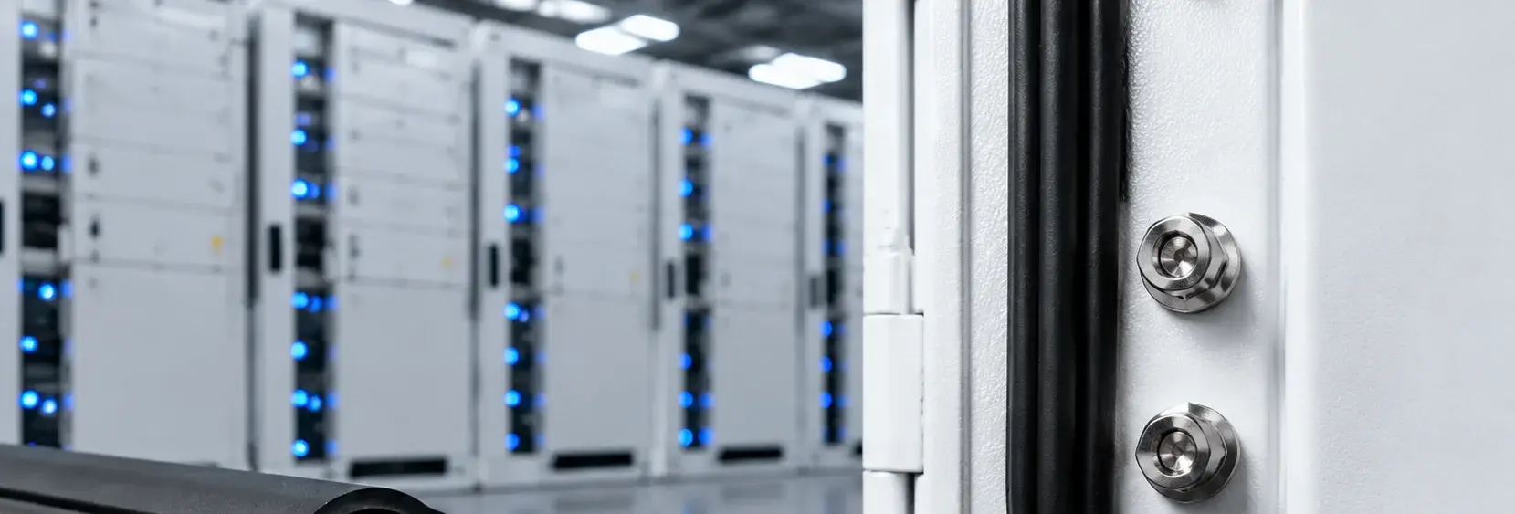
Cabinet Seals and Cable Entry: IP65 vs IP67 Plans
Choose between Plan A (IP65, EPDM seal strip, nylon cable gland) for indoor/sheltered outdoor and Plan B (IP67, thickened EPDM, 316L cable gland) for harsh outdoor. A wrong seal choice leads to water ingress, condensation, or dust accumulation causing false insulation alarms. Key differences: seal strip cross-section, gland material, breather valve type, and corrosion protection level
RISK AUDIT // ENGINEERING DIAGNOSIS
Procurement Pitfall Guide
"Field failures often trace back to a single overlooked seal detail — here are the most common ones."
QC-AUDIT // REV.5
SCALE 1:1 · 03 ITEMS
RISK-01
Water Ingress Due to Poor Cable Gland Sealing
Corrective Measures
RISK-02
Confusion in Waterproof Breather Valve Selection Leading to Functional Failure
Corrective Measures
RISK-03
Dust Ingress After Cabinet Seal Aging Leading to False Insulation Monitoring Alarms
Corrective Measures
FIELD-SPECIFIC INSIGHT
Seal Failure Chain: What to Specify in Your RFQ
The sealing level of energy storage cabinets ranges from IP54 to IP67. A poorly sealed cable gland leads to rainwater ingress, water accumulation at battery modules, insulation degradation, and shutdown. A waterproof but non-breathable valve causes negative pressure and condensation. Dust ingress through aged seal strips reduces creepage distance and triggers false alarms. Specify seal material, gland type, and breather valve correctly
WHAT TO CHECK
- 1Cable gland: Nylon PA66+EPDM for IP65 indoor; 316L+EPDM for IP67 outdoor. Specify IP rating per IEC 60529
- 2Seal strip: EPDM D-section for IP65; thickened for IP67. Shore A hardness affects long-term sealing
- 3Waterproof breather valve: PTFE membrane+PA for IP65; 316L+PTFE for IP67. Must balance pressure without letting water in
- 4Corrosion protection: Plan A uses C3 per ISO 12944-2; Plan B uses C4 harsh. Specify coating or material grade accordingly
- 5Maintenance: Inspect regularly; re-torque fasteners below specified torque; replace if corrosion exceeds surface area limit
| Check | Why it matters | What to specify |
|---|---|---|
| Seal strip material and cross-section | EPDM hardens over time; thickened section provides better compression set resistance for outdoor UV and temperature cycling | EPDM D-section for IP65 or thickened for IP67; Shore A hardness |
| Cable gland material and IP rating | Nylon glands crack under UV; 316L resists corrosion. IP67 required for outdoor to prevent water ingress | PA66+EPDM for IP65 indoor; 316L+EPDM for IP67 outdoor per IEC 62444 |
| Breather valve type | Non-waterproof plug lets rain in; non-breathable plug causes negative pressure and condensation | Waterproof breather valve with PTFE membrane; IP67 rated; flow rate matched to cabinet volume |
| Corrosion protection level | C3 vs C4 determines coating thickness and material selection; wrong level leads to premature corrosion | Plan A: C3 per ISO 12944-2; Plan B: C4 harsh. Specify HDG or 316L |
| Maintenance schedule | Regular inspection prevents seal failure; re-torque and replace critical fasteners on schedule | Inspect regularly; re-torque below specified torque; replace fasteners with corrosion exceeding limit |
All specifications must be verified against project-specific environmental conditions and applicable standards. The above data is based on typical indoor/sheltered outdoor (IP65) and outdoor harsh (IP67) scenarios
Evidence level: source-page-only
INDUSTRY TECH REFERENCE
Seal Strip Material Choice by Temperature Duty
Door seals are chosen by temperature range and site — standard outdoor cabinets and marine/extreme duty differ.
| Material | Temp. range | Typical use |
|---|---|---|
| EPDM | -40 to 120°C | Door sealing of standard outdoor cabinets |
| Silicone rubber | -60 to 200°C | Extreme temperature or marine duty |
Temperature ratings are verified common material data; choose by ambient temperature and sun exposure.
INDUSTRY TECH REFERENCE
The Hinge and Lock Corrosion Chain: From Condensation to Water Ingress
Door-hardware corrosion starts with condensation on the sealing face and builds to water ingress.
- 1Large indoor-outdoor temperature swings make the door sealing face condense and dry repeatedly
- 2Exposed carbon steel rusts in about 2 years (magnitude estimate), and rust swelling expands
- 3Rust on hinges, locks, and retainers sags the door and the seal strip no longer seats
- 4Sealing fails and rainwater seeps in through the door gap
- 5Insulation drops and leakage trips the system
~2-year carbon-steel corrosion (step 2) is a magnitude estimate.
PLAN COMPARISON
Three-Plan Core Parameter Comparison
Compare row by row. Click column headers to jump to plan details.
| A · Plan A · IP65 Indoor/Outdoor General | B · Plan B · IP67 Outdoor Harsh | C · Plan C · Extreme Environment/Marine Configuration | |
|---|---|---|---|
| 1. SEAL STRIP | |||
| SPEC | D-Section 10×15mm | D-Section 20×20mm | D-Section 20×20mm |
| MATERIAL | EPDM Rubber | EPDM Rubber | EPDM Rubber |
| GRADE | — | — | Temp. Range -60~200°C |
| FINISH | HDG >=55um per ISO 1461 | HDG >=55um per ISO 1461 | HDG >=55um per ISO 1461 |
| 2. NYLON CABLE GLAND | |||
| SPEC | PG7-PG21 | M16-M63 | IP67 |
| MATERIAL | PA66+EPDM | 316L+EPDM | 316L |
| FINISH | HDG >=55um per ISO 1461 | HDG >=55um per ISO 1461 | HDG >=55um per ISO 1461 |
| 3. WATERPROOF BREATHER VALVE | |||
| SPEC | M12×1.5 | 316L PTFE Membrane | D-Section 20×20mm |
| MATERIAL | PTFE Membrane+PA66 | 316L+PTFE | EPDM Rubber |
| GRADE | — | — | ATEX |
| FINISH | HDG >=55um per ISO 1461 | HDG >=55um per ISO 1461 | HDG >=55um per ISO 1461 |
| 4. FLAT WASHER | |||
| SPEC | M10-M12 | M10-M12 | Handheld |
| MATERIAL | 304 Stainless | 304 Stainless | EPDM Rubber |
| GRADE | A2 | A2 | — |
| FINISH | Passivated | Passivated | HDG >=55um per ISO 1461 |
| 5. FLAT WASHER | |||
| SPEC | M10-M12 | M10-M12 | Load Capacity 200kg |
| MATERIAL | 304 Stainless | 304 Stainless | 316L |
| GRADE | A2 | A2 | A4-80 |
| FINISH | Passivated | Passivated | HDG >=55um per ISO 1461 |
Plan A · IP65 Indoor/Outdoor General
C3 standard per ISO 12944-2
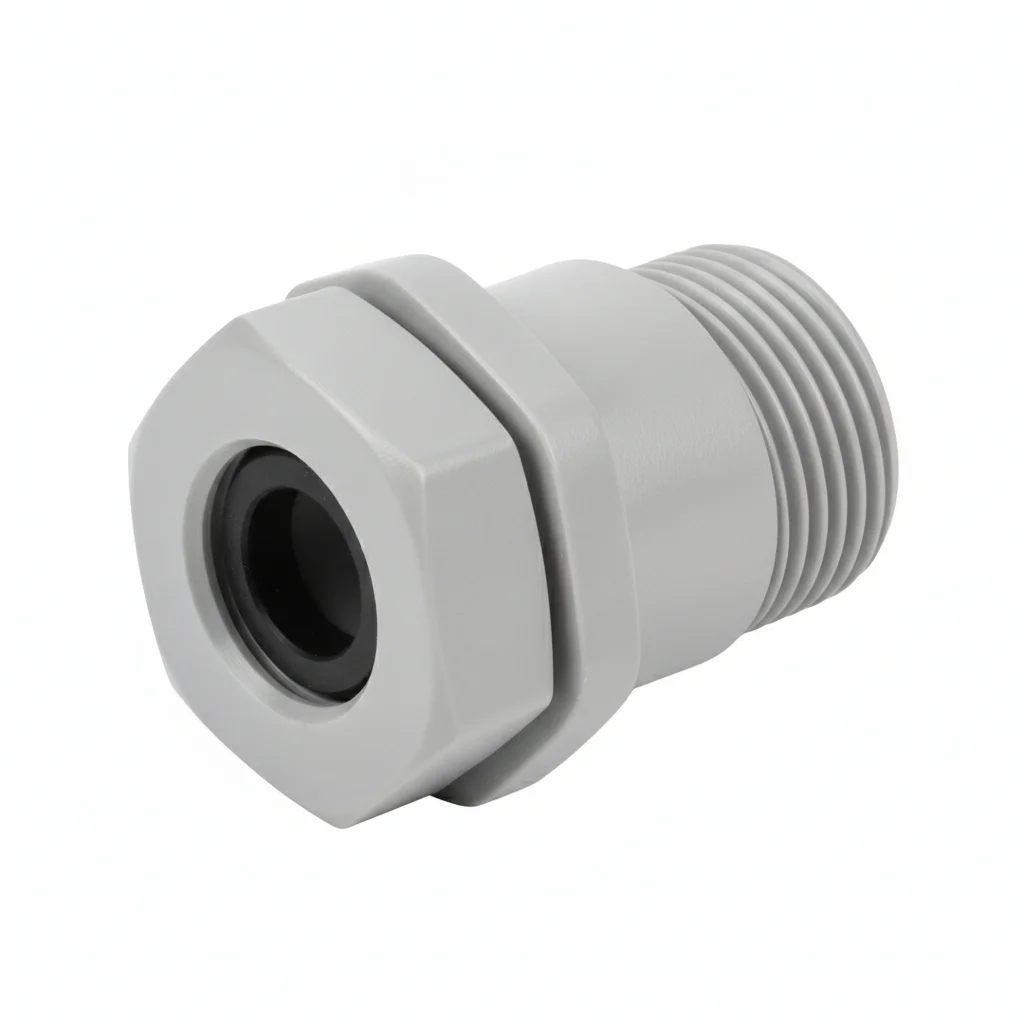
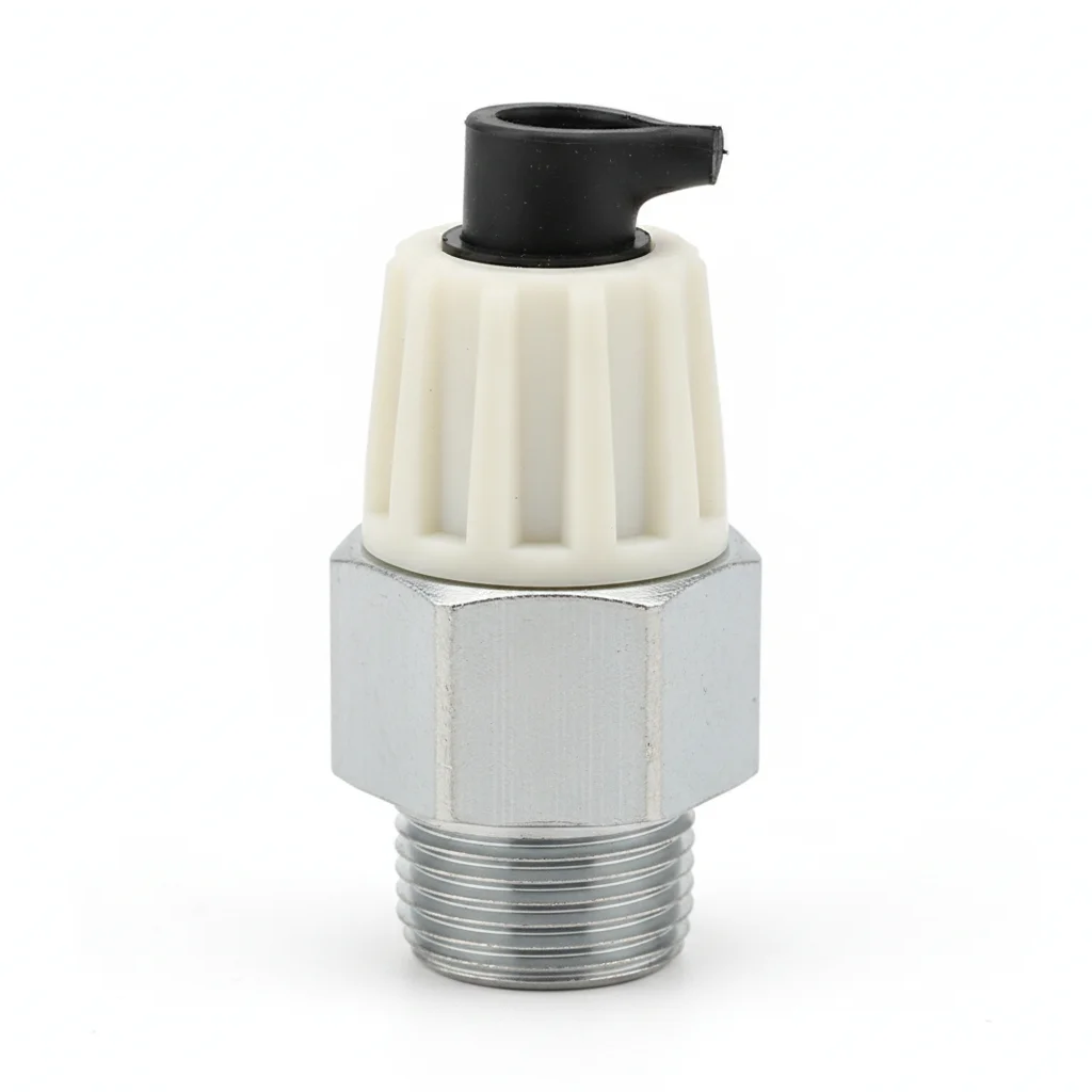
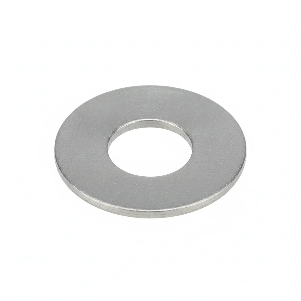
| Seal Strip | Nylon Cable Gland | Waterproof Breather Valve | Flat Washer | Flat Washer | |
|---|---|---|---|---|---|
| SPEC | D-Section 10×15mm | PG7-PG21 | M12×1.5 | M10-M12 | M10-M12 |
| MATERIAL | EPDM Rubber | PA66+EPDM | PTFE Membrane+PA66 | 304 Stainless | 304 Stainless |
| GRADE | — | — | — | A2 | A2 |
| FINISH | HDG >=55um per ISO 1461 | HDG >=55um per ISO 1461 | HDG >=55um per ISO 1461 | Passivated | Passivated |
| CORROSION | Not applicable (polymer) | C3 (ISO 12944-2) | C3 (ISO 12944-2) | C3 (ISO 12944-2) | C3 (ISO 12944-2) |
| TEMP | -20°C to +80°C | -20°C to +80°C | -20°C to +80°C | -20°C to +80°C | -20°C to +80°C |
| WEIGHT | ~0.5 kg/piece | ~0.5 kg/piece | ~0.5 kg/piece | ~0.005kg | ~0.005kg |
| MOQ | 100 pcs | 100 pcs | 100 pcs | 500 pcs | 500 pcs |
| PACK | VCI paper + carton | VCI paper + carton | VCI paper + carton | Plastic bag | Plastic bag |
| STD | ISO 898-1, GB/T 3098.1 | ISO 898-1, GB/T 3098.1 | ISO 898-1, GB/T 3098.1 | ISO 7089 | ISO 7089 |
| USE | Cabinet Door Seal | Cable Entry Seal | Cabinet Pressure Balance | Load distribution | Load distribution |
PROCEDURE
- Wipe the cabinet door frame and gland seating area with isopropyl alcohol to remove dust and grease before applying the EPDM D-section 10×15mm strip.
- Route cables through the PG7-PG21 PA66+EPDM gland with a downward U-bend so water cannot track along the cable into the enclosure.
- Tighten the gland locking nut evenly with a wrench until the EPDM cone visibly compresses around the cable; avoid over-tightening that could crush the insulation.
- Fit the M12×1.5 waterproof breather valve with PTFE membrane on the upper cabinet wall, ensuring the membrane side faces outward for pressure equalization.
- Seal any unused cable entry holes with blanking plugs and verify the door seal closes with even compression along the full perimeter.
COMMON ERRORS
| ✕ WRONG | CONSEQUENCE | ✓ CORRECT |
|---|---|---|
| Using a non-waterproof breather plug instead of a PTFE-membrane waterproof breather valve | Rainwater seeps into the cabinet through the plug, pooling on battery module casings and leading to corrosion and electrolyte leakage. | Specify a waterproof breather valve with PTFE microporous membrane (pore size 0.1-10μm) rated for IP65 or higher, matched to cabinet volume. |
| Overtightening the PA66+EPDM cable gland locking nut | The cable insulation is crushed, creating a path for moisture ingress and increasing the risk of short circuits. | Tighten only until the EPDM cone deforms around the cable; follow the gland manufacturer's recommended torque. |
| Installing the cable entry pointing upward without a drip loop | Water runs along the cable into the gland and cabinet, causing false insulation alarms or equipment damage. | Orient the gland downward and form a U-bend in the cable outside the cabinet so water drips off before reaching the gland. |
MAINTENANCE
Every 2 years, gently blow dust off the PTFE membrane of the breather valve with compressed air; replace if airflow drops below 50% of initial value. At each overhaul window, check the cable gland locking nut for looseness and inspect the EPDM seal strip for compression set; replace if set exceeds 25%.
Plan B · IP67 Outdoor Harsh
C4 Harsh per ISO 12944-2
| Thickened Seal Strip | Cable Gland | Metal Waterproof Breather Valve | Flat Washer | Flat Washer | |
|---|---|---|---|---|---|
| SPEC | D-Section 20×20mm | M16-M63 | 316L PTFE Membrane | M10-M12 | M10-M12 |
| MATERIAL | EPDM Rubber | 316L+EPDM | 316L+PTFE | 304 Stainless | 304 Stainless |
| GRADE | — | — | — | A2 | A2 |
| FINISH | HDG >=55um per ISO 1461 | HDG >=55um per ISO 1461 | HDG >=55um per ISO 1461 | Passivated | Passivated |
| CORROSION | Not applicable (polymer) | C3 (ISO 12944-2) | C3 (ISO 12944-2) | C3 (ISO 12944-2) | C3 (ISO 12944-2) |
| TEMP | -20°C to +80°C | -20°C to +80°C | -20°C to +80°C | -20°C to +80°C | -20°C to +80°C |
| WEIGHT | ~0.5 kg/piece | ~0.5 kg/piece | ~0.5 kg/piece | ~0.005kg | ~0.005kg |
| MOQ | 100 pcs | 100 pcs | 100 pcs | 500 pcs | 500 pcs |
| PACK | VCI paper + carton | VCI paper + carton | VCI paper + carton | Plastic bag | Plastic bag |
| STD | ISO 898-1, GB/T 3098.1 | ISO 898-1, GB/T 3098.1 | ISO 898-1, GB/T 3098.1 | ISO 7089 | ISO 7089 |
| USE | Outdoor Cabinet Door Seal | IP68 Cable Entry | Outdoor Waterproof & Breathable | Load distribution | Load distribution |
PROCEDURE
- Degrease the cable entry area with acetone and verify the cabinet surface roughness is below Ra 3.2 μm.
- Fit the 316L cable gland over the stripped cable, ensuring the EPDM sealing ring seats without twisting.
- Mount the thickened EPDM seal strip (20×20 mm) on the door frame, aligning corners without stretching.
- Tighten the gland nut to the torque recommended in IEC 62444—avoid over-compressing the cable.
- Position the 316L PTFE breather valve at the top of the cabinet, oriented to shed water, and secure with a 304 washer.
- Perform a water spray test per IEC 60529 IP67 to verify no ingress before commissioning.
COMMON ERRORS
| ✕ WRONG | CONSEQUENCE | ✓ CORRECT |
|---|---|---|
| Using a nylon gland instead of the specified 316L for outdoor exposure | UV radiation degrades nylon, causing cracking and water ingress within a few seasons. | Select the 316L gland with EPDM seal as per the BOM; verify material grade before installation. |
| Mounting the breather valve in a horizontal position or upside down | Rainwater can pool on the PTFE membrane and block airflow, causing pressure imbalance and seal stress. | Install the valve vertically with the membrane facing downward to allow drainage. |
MAINTENANCE
Seasonally inspect the 316L gland and thickened EPDM seal for UV cracking or compression set, and verify the breather valve's airflow is not blocked by debris—clean gently with compressed air. Replace any component showing Shore A hardness increase beyond specification or visible corrosion on the 316L surface.
Plan C · Extreme Environment/Marine Configuration
C5-M Extreme per ISO 12944-2
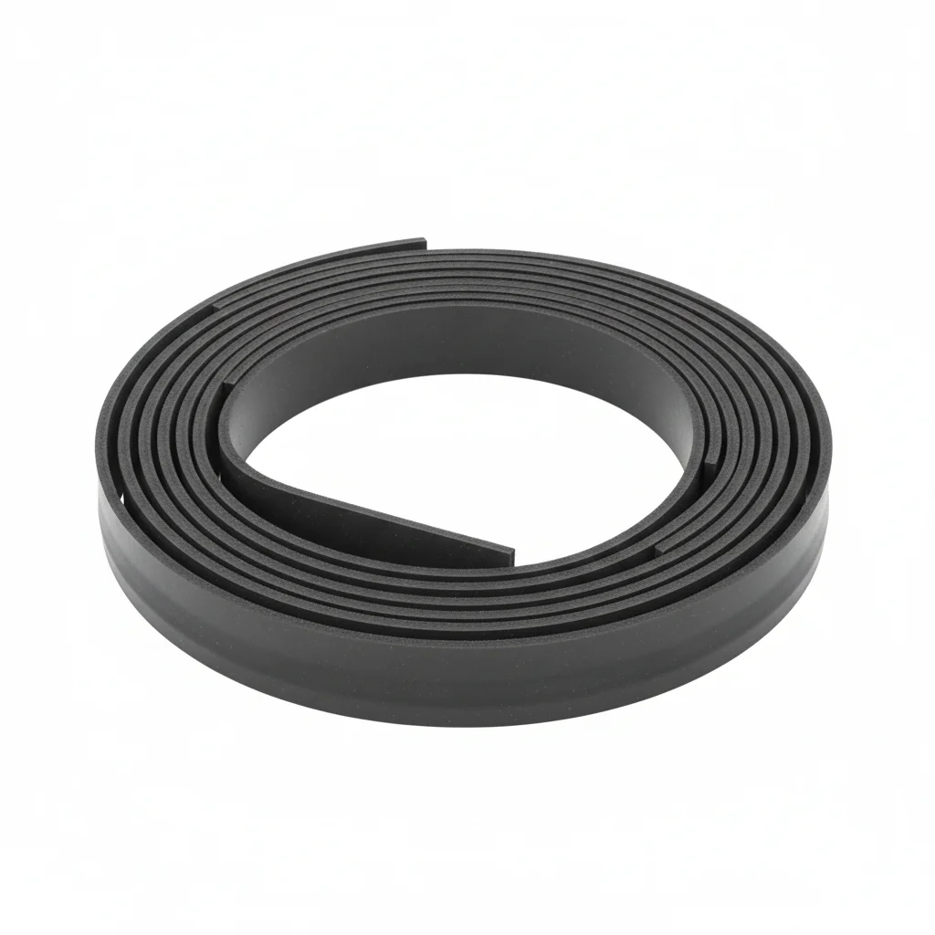
| Silicone Rubber Seal Strip | Door Lock | Explosion-Proof Seal Strip | Cabinet Seal Tester | Hinge | |
|---|---|---|---|---|---|
| SPEC | D-Section 20×20mm | IP67 | D-Section 20×20mm | Handheld | Load Capacity 200kg |
| MATERIAL | EPDM Rubber | 316L | EPDM Rubber | EPDM Rubber | 316L |
| GRADE | Temp. Range -60~200°C | — | ATEX | — | A4-80 |
| FINISH | HDG >=55um per ISO 1461 | HDG >=55um per ISO 1461 | HDG >=55um per ISO 1461 | HDG >=55um per ISO 1461 | HDG >=55um per ISO 1461 |
| CORROSION | Not applicable (polymer) | C3 (ISO 12944-2) | Not applicable (polymer) | Not applicable (polymer) | C3 (ISO 12944-2) |
| TEMP | -20°C to +80°C | -20°C to +80°C | -20°C to +80°C | -20°C to +80°C | -20°C to +80°C |
| WEIGHT | ~0.5 kg/piece | ~0.5 kg/piece | ~0.5 kg/piece | ~0.5 kg/piece | ~0.5 kg/piece |
| MOQ | 100 pcs | 100 pcs | 100 pcs | 100 pcs | 100 pcs |
| PACK | VCI paper + carton | VCI paper + carton | VCI paper + carton | VCI paper + carton | VCI paper + carton |
| STD | ISO 898-1, GB/T 3098.1 | ISO 898-1, GB/T 3098.1 | ISO 898-1, GB/T 3098.1 | ISO 898-1, GB/T 3098.1 | ISO 898-1, GB/T 3098.1 |
| USE | Extreme Temperature Seal | Marine Energy Storage Cabinet | Explosion-Proof Energy Storage Cabinet | Inspection Seal Integrity Test | Marine Cabinet Door Hinge |
PROCEDURE
- Clean the marine cabinet surfaces with MEK and achieve a surface roughness below Ra 1.6 μm.
- Apply a marine-grade anti-corrosion compound to all threaded entries, and use PTFE-encapsulated washers for isolation.
- Install the silicone rubber seal strip (rated -60~200°C) and door lock (IP67, 316L), ensuring compression meets the 20×20 mm cross-section specification.
- Secure the 316L hinges (load capacity 200 kg) with A4-80 fasteners, verifying alignment within 0.3 mm.
- Mount the explosion-proof EPDM seal strip on hazardous-area cabinets, confirming ATEX compliance.
- Validate seal integrity using the handheld cabinet seal tester, and document results for the compliance audit.
COMMON ERRORS
| ✕ WRONG | CONSEQUENCE | ✓ CORRECT |
|---|---|---|
| Substituting standard EPDM seal strip for the silicone rubber version in extreme temperature cycles | EPDM hardens below -20°C and loses elasticity, causing dust ingress and false insulation alarms. | Use the specified silicone rubber strip that remains flexible across the -60~200°C range. |
| Overtightening the 316L hinge bolts on thin marine cabinet walls | Local distortion of the door frame reduces seal compression, leading to water ingress. | Follow the torque value for A4-80 fasteners and use load-spreading washers to avoid over-stressing the frame. |
MAINTENANCE
At each overhaul window, inspect the silicone seal strip for compression set and the 316L components for pitting or crevice corrosion, especially around the hinges and lock. Verify the breather valve's PTFE membrane airflow is maintained; replace if clogged, and confirm the door seal tester reading remains within acceptable limits for IP67.
SELECTION GUIDE
Still Unsure Which Seal Plan Fits Your Site?
| Operating condition | Recommended option | Key basis |
|---|---|---|
| Indoor or sheltered outdoor site | Plan A · IP65 Nylon Standard: EPDM D-section seal strip (10×15mm), nylon cable gland PG7-PG21 (PA66+EPDM), waterproof breather valve M12×1.5 (PTFE membrane + PA66) | IEC 60529 (IP65); IEC 62444 (cable glands) |
| Outdoor unobstructed site | Plan B · IP67 316L Enhanced: thickened EPDM D-section seal strip (20×20mm), cable gland M16-M63 (316L+EPDM, IP68), metal waterproof breather valve (316L+PTFE membrane) | IEC 60529 (IP67); IEC 62444 (cable glands); ISO 12944-2 (C4) |
| Offshore platform / C5-M environment / highest protection requirements | Plan C · Extreme/Marine Configuration: silicone rubber seal strip (D-section 20×20mm, temperature range -60~200°C), 316L door lock (IP67), explosion-proof seal strip (ATEX), handheld cabinet seal tester | IEC 60529 (IP67); ISO 12944-2 (C5-M) |
| Site corrosivity category per ISO 12944-2 | C3 → Plan A materials/coating; C4 harsh → Plan B; C5-M extreme → Plan C (316L/Duplex/Titanium) | ISO 12944-2 (C3/C4/C5-M) |
SUPPLIER CAPABILITY
Quality, Delivery & Customization
Quality Control
- ✓MTC material certificates with every batch
- ✓Key parts sampled for hardness/salt spray/torque coefficient
- ✓100% inspection or AQL sampling before shipment
Delivery
- ✓Standard parts made to order: 7-15 days
- ✓Custom parts: 25-45 days
- ✓FOB/CIF/DDP supported
Customization
- ✓Drawing review and material matching
- ✓Non-standard sizes/heads/threads
- ✓Small-batch prototyping supported
Certification
- ✓Material certificates (MTC)
- ✓Spectrographic analysis reports
- ✓Salt spray test reports (on request)
MOQ: No MOQ for standard parts; custom parts assessed by process complexity
FAQ
FAQ
RELATED READING
Keep Reading & Next Step
NEXT: SELECTION & RFQ
Busbar & Electrical Connection UpgradeFollow this page's selection path to the same-scenario RFQ page.
RELATED TOPIC
Incoming Inspection of Transmission Fasteners: The Inspection Process Passed Down by Senior Workers, Don't Find It TroublesomeBEYOND TECHNICAL SPECS
Finding the right factory, controlling quality, delivering on time — that's the real challenge. We cover fasteners, rubber, plastics, industrial textiles. One team, end to end.
SEE CAPABILITIES →