
Energy Storage Insulation Washers: PC vs Epoxy vs Ceramic
DC arcs do not self-extinguish. Insulation washers prevent arcing. Compare PC (3mm, ≥2kV), epoxy (8mm, >10kV), and ceramic (3-5mm, >30kV) for battery rack isolation. Match voltage class and environment to avoid breakdown
RISK AUDIT // ENGINEERING DIAGNOSIS
Procurement Pitfall Guide
"Three failure modes that turn battery racks into live hazards"
QC-AUDIT // REV.5
SCALE 1:1 · 03 ITEMS
RISK-01
Insulation Washer Breakdown Under High Voltage Makes the Battery Rack Live
Corrective Measures
RISK-02
Bolt Insulation Sleeves Crack Under Sustained Compression — the Torque Itself Fractures the Sleeve
Corrective Measures
RISK-03
Surface Leakage on Insulation Washers in Condensing Humidity — a Sound Washer Still Leaks When Wet
Corrective Measures
FIELD-SPECIFIC INSIGHT
DC Arc Prevention: Insulation Washer Selection Checklist
In energy storage cabinets, DC voltage ranges from 500-1500V. Unlike AC, DC arcs do not self-extinguish. The insulation washer is the first line of defense. Key differences: material dielectric strength, creepage distance, and environmental resistance
WHAT TO CHECK
- 1PC washers (3mm, ≥2kV) are suitable for <500VDC but degrade with moisture and dust accumulation
- 2Epoxy washers (8mm, >10kV) provide higher creepage distance for >1000VDC and resist moisture better
- 3Ceramic washers (3-5mm, >30kV) offer the highest insulation but are brittle; use only in extreme environments
- 4Bolt insulation sleeves (nylon or epoxy) are mandatory to prevent metal bolts from becoming conductive paths
- 5Cable trays must not be overfilled; power and signal cables should be separated to avoid EMI and overheating
| Check | Why it matters | What to specify |
|---|---|---|
| Material dielectric strength | Determines maximum DC voltage the washer can withstand without breakdown | Specify withstand voltage ≥ system voltage × 1.5 (e. G. , ≥2kV for 500VDC) |
| Creepage distance | Dust and moisture reduce effective insulation; longer creepage reduces leakage risk | Minimum creepage distance per IEC 61439-1 for pollution degree 3 |
| Flame retardancy rating | Prevents fire propagation in case of arc or thermal runaway | UL 94 V-0 for all insulation components |
| Bolt insulation sleeve installation | Missing sleeve creates a metal conductive bridge bypassing the washer | Include insulation sleeve for every bolt passing through module mounting hole |
Insulation resistance should be tested with a 2500VDC megohmmeter during commissioning and annually. Values below 1MΩ indicate failure
Evidence level: source-page-only
INDUSTRY TECH REFERENCE
Fastener Scope by Storage Scale: Home, C&I, and Station
Before choosing insulation parts, find which tier the cabinet falls into — scale decides the cooling approach, and cooling decides which fasteners you need and how many.
| Storage type | Capacity | Typical form | Cooling | Fastener opportunity |
|---|---|---|---|---|
| Residential | 5–20 kWh | Wall-mounted cabinet | Natural convection | Small bolts + sealing parts |
| Commercial & industrial | 50–500 kWh | Floor-standing cabinet | Mostly forced air | Cabinet bolts + busbar connection hardware |
| Large stations | 1–100 MWh+ | 20/40-ft container | Mostly liquid cooling | Full fastener scope + consumables (seals, O-rings, insulation washers) |
Capacity tiers and cooling approaches follow common industry practice; confirm against the project's actual design parameters.
INDUSTRY TECH REFERENCE
How Condensation Turns the Insulation Washer into a Leakage Path
Example: an outdoor storage cabinet with high internal humidity and large day/night temperature swings.
- 1Internal humidity must stay below 90% RH — sustained exceedance is where condensation forms
- 2Day/night temperature swings make condensation settle on the washer surface as a water film
- 3The film turns a dry insulation surface into a leakage path — condensation is a direct short-circuit risk
- 4In a 1500 V DC system, a leakage path can draw short-circuit current on the order of 100 kA
- 5Countermeasure: hold humidity below 90% RH; before and after the rainy season, check washer surfaces for water film
"Short-circuit current 100 kA" is a magnitude estimate; other figures are industry research values.
INDUSTRY TECH REFERENCE
Which Standards Govern Insulation Coordination
Verify insulation and safety performance against this standard set — each standard maps to a specific fastener or insulation-part check.
Standard list for cross-checking; apply the version in force for the project.
PLAN COMPARISON
Three-Plan Core Parameter Comparison
Compare row by row. Click column headers to jump to plan details.
| A · Plan A · Low Voltage Energy Storage Standard Insulation | B · Plan B · High Voltage Container Energy Storage Enhanced | C · Plan C · Extreme Environment/Offshore Configuration | |
|---|---|---|---|
| 1. POLYCARBONATE INSULATION WASHER | |||
| SPEC | 3mm thick, withstand voltage ≥2kV | 8mm thick, withstand voltage >10kV | 10mm thick |
| MATERIAL | Polycarbonate | Epoxy Resin | Epoxy Resin |
| GRADE | UL 94 V-0 | UL 94 V-0 | Withstand voltage >20kV |
| FINISH | HDG >=55um per ISO 1461 | HDG >=55um per ISO 1461 | HDG >=55um per ISO 1461 |
| 2. NYLON INSULATION BOLT SLEEVE | |||
| SPEC | Wall thickness 1.5mm M6-M10 | 8mm thick | 3-5mm thick |
| MATERIAL | PA66 | Polycarbonate | Al₂O₃ Ceramic |
| GRADE | UL 94 V-2 | Withstand voltage ≥5kV | Withstand voltage >30kV |
| FINISH | HDG >=55um per ISO 1461 | HDG >=55um per ISO 1461 | HDG >=55um per ISO 1461 |
| 3. FLAME-RETARDANT CABLE TRAY | |||
| SPEC | Width 25-60mm | Wall thickness 2mm | M6-M12 |
| MATERIAL | PVC V-0 Flame Retardant | Epoxy Resin | PTFE |
| GRADE | / | UL 94 V-0 | Temperature resistance 260°C |
| FINISH | HDG >=55um per ISO 1461 | HDG >=55um per ISO 1461 | HDG >=55um per ISO 1461 |
| 4. FLAT WASHER | |||
| SPEC | M10-M12 | Width 40-80mm | Custom |
| MATERIAL | 304 Stainless | Steel + Fireproof Coating | Silicone Rubber |
| GRADE | A2 | Fire resistance 30min | Withstand voltage >10kV |
| FINISH | Passivated | HDG >=55um per ISO 1461 | HDG >=55um per ISO 1461 |
| 5. FLAT WASHER | |||
| SPEC | M10-M12 | M10-M12 | 2500VDC |
| MATERIAL | 304 Stainless | 304 Stainless | — |
| GRADE | A2 | A2 | — |
| FINISH | Passivated | Passivated | HDG >=55um per ISO 1461 |
SELECTION GUIDE
Choose by Voltage Class
| Operating condition | Recommended option | Key basis |
|---|---|---|
| <500VDC low voltage energy storage (residential/small commercial) | Plan A – PC insulation washer (3mm, withstand ≥2kV) standard insulation | UL 1973 (stationary storage battery safety) |
| >1000VDC high voltage container (>1MWh) | Plan B – epoxy separator (8mm, withstand >10kV) enhanced insulation | IEC 61439-1 creepage distance, IEC 60664-1 insulation coordination |
| Battery rack fixing bolt passing through module mounting hole | Add nylon (PA66) insulation sleeve (wall ≥1.5mm) + insulation washer | Prevents metal conductive bridge that bypasses insulation (UL 1973) |
| Cable tray bundling signal/control cables | Fill rate ≤60%, lay power and signal in separate trays (spacing ≥200mm), flame retardant V-0 | Prevents overheating and EMI packet loss, limits fire spread (UL 9540A) |
Plan A · Low Voltage Energy Storage Standard Insulation
C3 (ISO 12944-2) indoor, dry environment
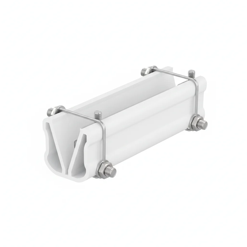
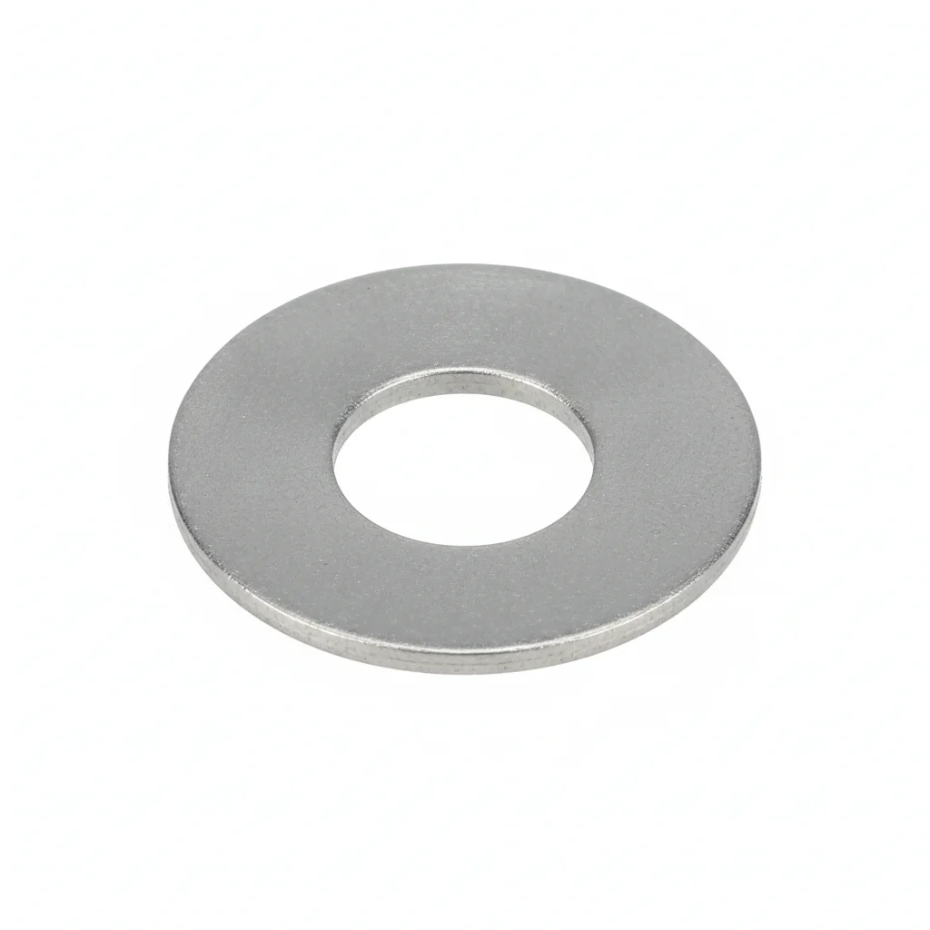
| Polycarbonate Insulation Washer | Nylon Insulation Bolt Sleeve | Flame-Retardant Cable Tray | Flat Washer | Flat Washer | |
|---|---|---|---|---|---|
| SPEC | 3mm thick, withstand voltage ≥2kV | Wall thickness 1.5mm M6-M10 | Width 25-60mm | M10-M12 | M10-M12 |
| MATERIAL | Polycarbonate | PA66 | PVC V-0 Flame Retardant | 304 Stainless | 304 Stainless |
| GRADE | UL 94 V-0 | UL 94 V-2 | / | A2 | A2 |
| FINISH | HDG >=55um per ISO 1461 | HDG >=55um per ISO 1461 | HDG >=55um per ISO 1461 | Passivated | Passivated |
| CORROSION | C3 (ISO 12944-2) | C3 (ISO 12944-2) | C3 (ISO 12944-2) | C3 (ISO 12944-2) | C3 (ISO 12944-2) |
| TEMP | -20°C to +80°C | -20°C to +80°C | -20°C to +80°C | -20°C to +80°C | -20°C to +80°C |
| WEIGHT | ~0.5 kg/piece | ~0.5 kg/piece | ~0.5 kg/piece | ~0.005kg | ~0.005kg |
| MOQ | 100 pcs | 100 pcs | 100 pcs | 500 pcs | 500 pcs |
| PACK | VCI paper + carton | VCI paper + carton | VCI paper + carton | Plastic bag | Plastic bag |
| STD | ISO 898-1, GB/T 3098.1 | ISO 898-1, GB/T 3098.1 | ISO 898-1, GB/T 3098.1 | ISO 7089 | ISO 7089 |
| USE | Battery rack and module isolation | Bolt insulation isolation | Control/Signal cable laying | Load distribution | Load distribution |
PROCEDURE
- Clean the battery rack mounting surface with anhydrous alcohol and let dry for 30 minutes to remove dust and moisture that reduce creepage distance.
- Place the 3mm polycarbonate insulation washer (≥2kV withstand) between the battery module and rack; center it over the mounting hole.
- Slide the PA66 nylon bolt sleeve (wall thickness 1.5mm, UL 94 V-2) over the bolt, covering the section that passes through the rack.
- Insert the bolt through the sleeve and washer, then tighten to a snug fit—do not over-torque, as excessive compression can crack the PC washer.
- After all bolts are installed, perform a DC 2500V insulation resistance test between the battery rack and ground, verifying ≥100MΩ.
COMMON ERRORS
| ✕ WRONG | CONSEQUENCE | ✓ CORRECT |
|---|---|---|
| Forgetting the nylon bolt sleeve on a rack fixing bolt | The metal bolt directly bridges the battery module shell and rack, creating a conductive path that bypasses the insulation washer and can energize the rack during a fault. | Every bolt passing through the rack must have a PA66 sleeve (≥1.5mm wall) plus a PC washer under the head; verify sleeve covers the full rack thickness. |
| Using a water-based cleaner or wiping dust off the PC washer | Moisture residue on the surface reduces creepage distance; wiping can generate static charge that attracts more dust, accelerating tracking and breakdown under DC voltage. | Blow dust off with dry compressed air; for stubborn stains, wipe with anhydrous alcohol and let dry 30 minutes before re-energizing. |
| Selecting a 3mm PC washer for a 600VDC busbar | The washer's dielectric strength (≥2kV) is insufficient for the voltage class, risking breakdown and a live rack. | Match washer thickness to voltage: 3mm for <500VDC, 5mm for 500-1000VDC, 8mm for >1000VDC; for >1000VDC use epoxy separators (Plan B). |
MAINTENANCE
During annual outage inspections, test insulation resistance with a 2500V DC Megger; rack-to-ground readings must be ≥100MΩ. Clean surfaces with dry compressed air or anhydrous alcohol as needed, and re-test 48 hours after rain or in dry weather.
Plan B · High Voltage Container Energy Storage Enhanced
C4 Harsh per ISO 12944-2
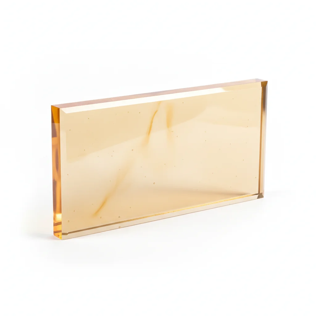
| Epoxy Resin Insulation Separator | Thickened Insulation Washer | Epoxy Resin Insulation Bolt Sleeve | Fireproof Cable Tray | Flat Washer | |
|---|---|---|---|---|---|
| SPEC | 8mm thick, withstand voltage >10kV | 8mm thick | Wall thickness 2mm | Width 40-80mm | M10-M12 |
| MATERIAL | Epoxy Resin | Polycarbonate | Epoxy Resin | Steel + Fireproof Coating | 304 Stainless |
| GRADE | UL 94 V-0 | Withstand voltage ≥5kV | UL 94 V-0 | Fire resistance 30min | A2 |
| FINISH | HDG >=55um per ISO 1461 | HDG >=55um per ISO 1461 | HDG >=55um per ISO 1461 | HDG >=55um per ISO 1461 | Passivated |
| CORROSION | C3 (ISO 12944-2) | C3 (ISO 12944-2) | C3 (ISO 12944-2) | C3 (ISO 12944-2) | C3 (ISO 12944-2) |
| TEMP | -20°C to +80°C | -20°C to +80°C | -20°C to +80°C | -20°C to +80°C | -20°C to +80°C |
| WEIGHT | ~0.5 kg/piece | ~0.5 kg/piece | ~0.5 kg/piece | ~0.5 kg/piece | ~0.005kg |
| MOQ | 100 pcs | 100 pcs | 100 pcs | 100 pcs | 500 pcs |
| PACK | VCI paper + carton | VCI paper + carton | VCI paper + carton | VCI paper + carton | Plastic bag |
| STD | ISO 898-1, GB/T 3098.1 | ISO 898-1, GB/T 3098.1 | ISO 898-1, GB/T 3098.1 | ISO 898-1, GB/T 3098.1 | ISO 7089 |
| USE | High voltage battery rack module isolation | High voltage battery rack | High voltage bolt insulation | High voltage high current cable laying | Load distribution |
PROCEDURE
- Clean the epoxy resin separator and thickened insulation washer surfaces with anhydrous alcohol to remove any dust or grease that could compromise the >10kV withstand voltage.
- Position the epoxy resin insulation bolt sleeve (wall thickness 2mm) over each M6-M10 bolt, ensuring full coverage of the section passing through the battery rack.
- Place the 8mm thickened insulation washer between the bolt head and the battery rack, and the epoxy separator between the module and rack to maintain the required creepage distance for >1000VDC.
- Tighten bolts in a cross-pattern sequence to uniform torque, using a calibrated wrench to avoid over-stressing the epoxy components.
- After installation, perform an insulation resistance test using a 2500VDC Megger, confirming readings ≥100MΩ between the battery rack and ground, and log results.
COMMON ERRORS
| ✕ WRONG | CONSEQUENCE | ✓ CORRECT |
|---|---|---|
| Omitting the epoxy bolt sleeve on a fixing bolt | The metal bolt directly contacts the module shell, creating a conductive path that bypasses the insulation washer, leading to leakage current and potential electrocution. | Install the epoxy resin insulation bolt sleeve (wall thickness 2mm) on every bolt passing through the battery rack, and verify with a Megger that resistance ≥100MΩ. |
| Using a thinner polycarbonate washer (3mm) instead of the 8mm thickened version | The 3mm washer is rated for only ≥2kV, insufficient for >1000VDC systems, risking dielectric breakdown and arcing. | Select the 8mm thickened insulation washer with ≥5kV withstand voltage for all high-voltage battery rack isolations. |
MAINTENANCE
At each overhaul window or annually, clean the epoxy surfaces with dry compressed air to prevent dust accumulation that reduces creepage distance. Perform insulation resistance testing with a 2500VDC Megger, ensuring ≥100MΩ. Replace any epoxy separator or washer showing cracks or tracking paths. Verify the fireproof cable tray's integrity, as it provides 30min fire resistance.
Plan C · Extreme Environment/Offshore Configuration
C5-M Extreme per ISO 12944-2
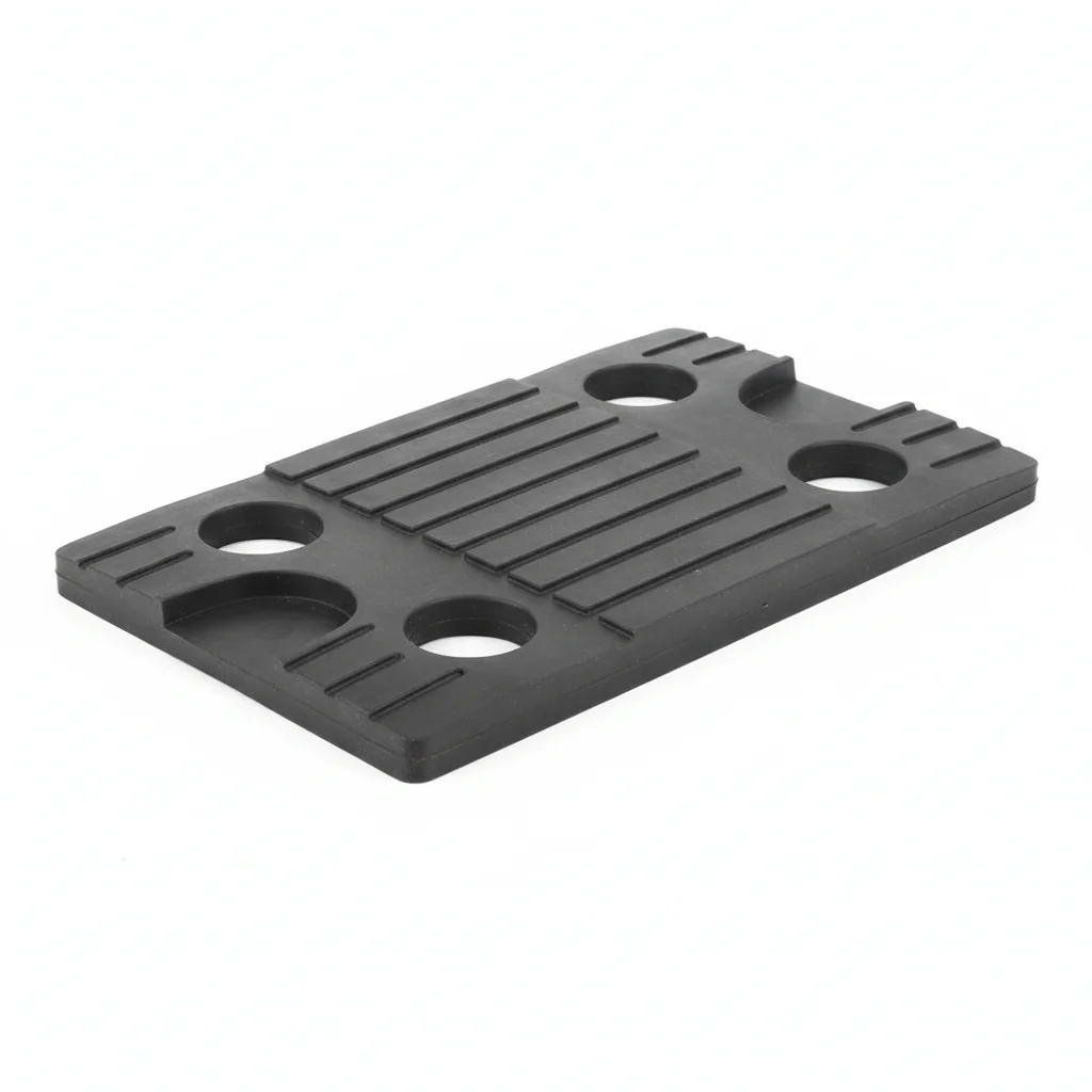
| Epoxy Resin Separator | Ceramic Insulation Washer | Insulation Bolt Sleeve | Silicone Rubber Insulation Pad | Insulation Resistance Tester | |
|---|---|---|---|---|---|
| SPEC | 10mm thick | 3-5mm thick | M6-M12 | Custom | 2500VDC |
| MATERIAL | Epoxy Resin | Al₂O₃ Ceramic | PTFE | Silicone Rubber | — |
| GRADE | Withstand voltage >20kV | Withstand voltage >30kV | Temperature resistance 260°C | Withstand voltage >10kV | — |
| FINISH | HDG >=55um per ISO 1461 | HDG >=55um per ISO 1461 | HDG >=55um per ISO 1461 | HDG >=55um per ISO 1461 | HDG >=55um per ISO 1461 |
| CORROSION | C3 (ISO 12944-2) | C3 (ISO 12944-2) | C3 (ISO 12944-2) | C3 (ISO 12944-2) | C3 (ISO 12944-2) |
| TEMP | -20°C to +80°C | -20°C to +80°C | -20°C to +80°C | -20°C to +80°C | -20°C to +80°C |
| WEIGHT | ~0.5 kg/piece | ~0.5 kg/piece | ~0.5 kg/piece | ~0.5 kg/piece | ~0.5 kg/piece |
| MOQ | 100 pcs | 100 pcs | 100 pcs | 100 pcs | 100 pcs |
| PACK | VCI paper + carton | VCI paper + carton | VCI paper + carton | VCI paper + carton | VCI paper + carton |
| STD | ISO 898-1, GB/T 3098.1 | ISO 898-1, GB/T 3098.1 | ISO 898-1, GB/T 3098.1 | ISO 898-1, GB/T 3098.1 | ISO 898-1, GB/T 3098.1 |
| USE | High voltage module isolation | Highest insulation level | High temperature environment insulation | Elastic insulation isolation | Periodic insulation resistance testing |
PROCEDURE
- Clean all ceramic and epoxy surfaces with anhydrous alcohol; avoid water-based cleaners that leave residues. Ensure surfaces are dry before assembly.
- Fit the PTFE insulation bolt sleeve over each bolt to provide high-temperature insulation up to 260°C, especially in offshore environments.
- Place ceramic insulation washers (3-5mm thick, >30kV withstand) between bolt heads and the structure, and epoxy resin separators (10mm, >20kV) for module isolation.
- Tighten bolts using a calibrated torque wrench, applying even pressure to prevent cracking the brittle ceramic washers.
- After installation, use the 2500VDC insulation resistance tester to verify ≥100MΩ between the rack and ground, and document readings for compliance with C5-M standards.
COMMON ERRORS
| ✕ WRONG | CONSEQUENCE | ✓ CORRECT |
|---|---|---|
| Using a metal bolt without the PTFE sleeve in high-temperature zones | The bolt becomes a conductive path and may overheat, compromising insulation and causing arcing in extreme environments. | Always install the PTFE insulation bolt sleeve (rated 260°C) on every bolt, especially where temperatures may rise. |
| Over-tightening ceramic washers, causing cracking | Cracked ceramic loses its >30kV insulation capability, leading to potential breakdown and arcing. | Use a torque wrench set to the manufacturer's specification, and inspect ceramic washers for cracks after tightening; replace any damaged units. |
MAINTENANCE
Conduct inspections at each scheduled maintenance window, cleaning insulation surfaces with dry compressed air to remove salt deposits and dust. Test insulation resistance with the 2500VDC tester, ensuring ≥100MΩ. Replace any ceramic washers showing chips or cracks, and re-apply protective coatings as needed to maintain C5-M corrosion protection.
REFERENCED STANDARDS
Referenced Standards
SUPPLIER CAPABILITY
Quality, Delivery & Customization
Quality Control
- ✓MTC material certificates with every batch
- ✓Key parts sampled for hardness/salt spray/torque coefficient
- ✓100% inspection or AQL sampling before shipment
Delivery
- ✓Standard parts made to order: 7-15 days
- ✓Custom parts: 25-45 days
- ✓FOB/CIF/DDP supported
Customization
- ✓Drawing review and material matching
- ✓Non-standard sizes/heads/threads
- ✓Small-batch prototyping supported
Certification
- ✓Material certificates (MTC)
- ✓Spectrographic analysis reports
- ✓Salt spray test reports (on request)
MOQ: No MOQ for standard parts; custom parts assessed by process complexity
FAQ
FAQ
RELATED READING
Keep Reading & Next Step
BEYOND TECHNICAL SPECS
Finding the right factory, controlling quality, delivering on time — that's the real challenge. We cover fasteners, rubber, plastics, industrial textiles. One team, end to end.
SEE CAPABILITIES →