
PV Foundation Hardware: Ground Screws vs Embedded Bolts vs Concrete
Selecting the right foundation hardware for ground-mounted solar farms affects cost, schedule, and long-term stability. Compare helical ground screws (Q235B HDG), embedded bolts (grade 8.8 HDG), and concrete foundations on pullout resistance, corrosion in acidic soil, and verticality tolerance. Key standards: GB 50797, ISO 1461
RISK AUDIT // ENGINEERING DIAGNOSIS
Procurement Pitfall Avoidance Guide
"Field failures in PV foundation hardware often trace to three overlooked details: pullout safety in loose ground, galvanized coating life in aggressive soil, and verticality control during pile driving."
QC-AUDIT // REV.5
SCALE 1:1 · 03 ITEMS
RISK-01
Insufficient Pullout Resistance of Helical Ground Screws in Loose Soil
Corrective Measures
RISK-02
Accelerated Consumption of Galvanized Coating on Helical Ground Screws in Acidic Soil
Corrective Measures
RISK-03
Difficulty Adjusting Mounting Structure Installation Due to Ground Screw Verticality Deviation
Corrective Measures
FIELD-SPECIFIC INSIGHT
Foundation Hardware Selection: 4 Critical Checks for PV Mounting
The foundation hardware choice impacts not only cost but also long-term structural integrity. The most overlooked differences are pullout resistance in loose soil, galvanized coating life in acidic soil, and verticality deviation during installation. Use these checks to specify the right hardware
WHAT TO CHECK
- 1Check pullout resistance: In sandy soil (φ=30°), a φ76mm ground screw provides only 5-8kN pullout; ensure depth ≥1. 6m to meet GB 50797 safety factor ≥1.6
- 2Check coating thickness: In acidic soil (pH<5), HDG consumption is 8-12μm/year
- 3Check verticality tolerance: Deviation >2% causes bolt hole misalignment
- 4Check fastener grade: Use grade 8.8 bolts for flange connections; verify torque retention per maintenance schedule
| Check | What to specify | Why it matters |
|---|---|---|
| Pullout resistance in loose soil | Minimum pile depth 1. 6m in sand; pullout test per GB 50797 with safety factor ≥1.6 | — |
| Galvanized coating thickness | Consider epoxy coating for pH<5 | 85μm coating depletes in 10 years in acidic soil (pH<5), reducing load capacity |
| Verticality deviation | Inspection after installation | >2% deviation adds 20-30 min rework per pile |
| Bolt grade and torque | Grade 8.8 HDG bolts; torque to 80% of proof load; re-torque after 6 months | Grade 8.8 bolts required for flange connections; undertorqued bolts loosen under vibration |
Data based on typical soil conditions; actual values require geotechnical report. Coating life estimates assume C3 environment per ISO 12944-2
Evidence level: source-page-only
INDUSTRY TECH REFERENCE
Foundation Options Compared: Ground Screws vs Embedded Bolts
Load capacity, relative cost, and acceptance gates are where the two schemes differ most. The comparison:
| Item | Helical ground screw | Embedded anchor bolt + concrete |
|---|---|---|
| Installation speed | Rotary driving, about 3 min per pile | Embedment ≥10d (240 mm for M24) with second-stage grouting |
| Pullout / capacity | φ76 in clay ≈15-20 kN; in sand only 5-8 kN (magnitude estimate) | 5-10× a ground screw, independent of soil type (magnitude estimate) |
| Relative cost | Baseline (lowest) | 2-3× a ground screw (magnitude estimate) |
| Key fasteners | Flange bolts M12-M16, grade 8.8 HDG | Anchors M20-M30, grade 8.8 HDG/Dacromet; U-bolts M16-M30 |
| Acceptance gate | Full-array re-torque within 72 h | Full second-stage grout; sample 10% of torque yearly |
"~3 min per pile" is a field experience value; pullout capacities and the capacity/cost ratios are magnitude estimates for comparison only.
INDUSTRY TECH REFERENCE
How a Sand-Soil Ground Screw Gets Pulled Out
Sand has no cohesion — a helical screw anchors only through the soil compressed under its helix. The failure chain:
- 1A φ76 screw resists about 15-20 kN in clay, but only 5-8 kN in sand (magnitude estimate)
- 2At 35 m/s wind, uplift on one pile reaches about 10-15 kN (magnitude estimate) — sand piles drop below a safety factor of 1
- 3Freeze-thaw cycling loosens the soil year after year and the compressed-soil anchorage fails bit by bit
- 4The moment wind uplift exceeds pullout resistance, the screw lifts out and the flange joint opens
- 5One pulled pile drags the whole row over — repair runs in the cramped space under the array at 3-5× the cost of new build (magnitude estimate)
Pullout capacity, uplift force, and repair-cost ratio are magnitude estimates.
INDUSTRY TECH REFERENCE
Ground Screw Installation and Acceptance Checks
Verticality and re-torque are the two gates most often waived in acceptance — and the first to fail when trouble hits.
- Run pullout tests on trial piles per code before the full install: where sand/desert resistance is weak, deepen to ≥2 m and enlarge the helix
- Fit the pile driver with an inclination sensor to hold verticality within ±0.5° (recommended) — past 2°, a 2 m pile top shifts about 70 mm (2 m × tan2°), and misaligned flange holes force on-site reaming
- Flange bolts M12-M16, grade 8.8 HDG, torqued diagonally in steps, then re-torque the whole array within 72 h (recommended)
±0.5° and the 72 h re-torque are recommended values; the 70 mm offset is computed as 2 m × tan2°; pullout figures are magnitude estimates.
INDUSTRY TECH REFERENCE
How Poor Grouting Dooms Embedded Anchor Bolts
Embedded anchors are strong, but the second-stage grout is their weakest link. The degradation path:
- 1Anchor capacity runs 5-10× that of a ground screw and ignores soil type (magnitude estimate) — at 2-3× the cost (magnitude estimate)
- 2Embedment ≥10d (240 mm for M24); everything hinges on fully compacted second-stage grout
- 3Voids in the grout → cracks open under wind load → rainwater works its way in
- 4Freeze-thaw cycles widen the cracks year after year, while the U-bolt — carrying the full wind bending moment — degrades along with them
- 5The foundation is written off in 5-8 years (typical cycle) — repair runs near 3-5× the cost of new build (magnitude estimate)
Capacity/cost ratios and the repair-cost ratio are magnitude estimates; the 5-8-year write-off window follows industry experience.
INDUSTRY TECH REFERENCE
Embedded Anchor O&M: Torque Sampling After Commissioning
Wind-induced loosening is the dominant failure mode for anchor and U-bolts — sample torque on a fixed cycle after commissioning.
- Anchors M20-M30, grade 8.8, hot-dip galvanized (≥85 μm or per GB/T 13912 tiers) or Dacromet
- U-bolts get nylon-insert lock nuts plus spring washers — they carry the entire wind bending moment, so anti-loosening starts here
- Sample about 10% of bolt torque each year; if any value drops more than 20%, re-torque the whole batch (recommended)
- Slope the foundation top to shed water so it cannot seep down along the bolts
The 10% sampling rate and 20% degradation threshold are recommended values.
PLAN COMPARISON
Three-Plan Core Parameter Comparison
Compare row by row. Click column headers to jump to plan details.
| A · Plan A · Helical Ground Screws | B · Plan B · Embedded Bolts + Concrete Foundation | C · Plan C · Concrete Independent Foundation | |
|---|---|---|---|
| 1. HELICAL GROUND SCREW | |||
| SPEC | Diameter 76/89mm, length 1.5-2.5m | M20-M30, L-shaped/J-shaped/Straight | M20-M30 |
| MATERIAL | Q235B hot-dip galvanized ≥65μm | Grade 8.8 hot-dip galvanized/Dacromet | Hot-dip galvanized ≥65μm |
| GRADE | — | Grade 8.8 | Grade 8.8 |
| FINISH | HDG, >=55um per ISO 1461 | HDG, >=55um per ISO 1461 | HDG, >=55um per ISO 1461 |
| 2. CONNECTION FLANGE | |||
| SPEC | 8-12mm thick steel plate | M16-M24 | Reinforcement per design |
| MATERIAL | Q235B hot-dip galvanized | Hot-dip galvanized ≥65μm | HRB400 |
| GRADE | — | Grade 8.8 | — |
| FINISH | HDG, >=55um per ISO 1461 | HDG, >=55um per ISO 1461 | HDG, >=55um per ISO 1461 |
| 3. LOCK BOLT | |||
| SPEC | M12-M16 | Customized per design | 20-30mm thick steel plate |
| MATERIAL | Carbon steel hot-dip galvanized | Q235B hot-dip galvanized | Q235B hot-dip galvanized |
| GRADE | Grade 8.8 | — | — |
| FINISH | HDG, >=55um per ISO 1461 | HDG, >=55um per ISO 1461 | HDG, >=55um per ISO 1461 |
SELECTION GUIDE
How to Choose a Foundation Scheme Based on Project Conditions?
| Operating condition | Recommended option | Key basis |
|---|---|---|
| Soft soil, sandy soil, plastic soil; tight schedule; cost-sensitive | Plan A Helical Ground Screws (Q235B hot-dip galvanized) | GB 50797 pullout safety factor ≥1.6; installs in ≤3 minutes per pile with no concrete curing per NB/T 10115-2018 |
| Complex geology (rock, hard clay); permanent structure; high load-bearing capacity | Plan B Embedded Bolts + Concrete Foundation | Curing ≥7 days, higher integrity and settlement resistance, suitable for permanent high-load stations |
| Very poor geology (silt, backfill); heavy load; high stability requirement | Plan C Concrete Independent Foundation | Curing ≥14 days, greatest stability and strongest resistance to uneven settlement |
Plan A · Helical Ground Screws
C3 standard environment per ISO 12944-2
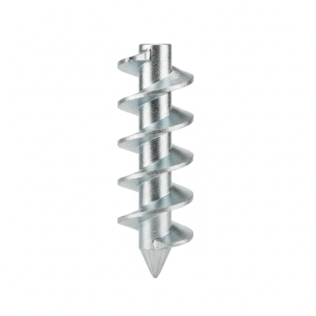
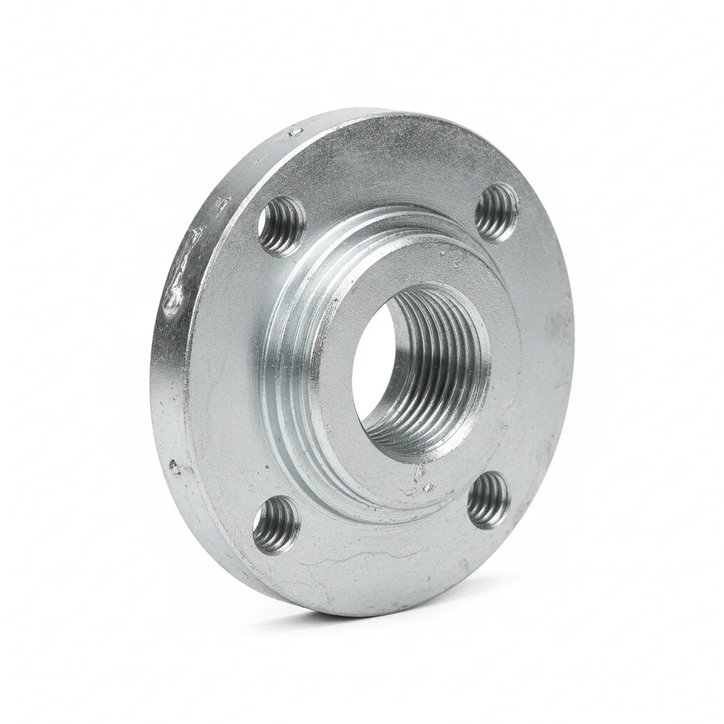
| Helical Ground Screw | Connection Flange | Lock Bolt | |
|---|---|---|---|
| SPEC | Diameter 76/89mm, length 1.5-2.5m | 8-12mm thick steel plate | M12-M16 |
| MATERIAL | Q235B hot-dip galvanized ≥65μm | Q235B hot-dip galvanized | Carbon steel hot-dip galvanized |
| GRADE | — | — | Grade 8.8 |
| FINISH | HDG, >=55um per ISO 1461 | HDG, >=55um per ISO 1461 | HDG, >=55um per ISO 1461 |
| CORROSION | C3 (ISO 12944-2) | C3 (ISO 12944-2) | C3 (ISO 12944-2) |
| TEMP | -20°C to +80°C | -20°C to +80°C | -20°C to +80°C |
| WEIGHT | ~0.5 kg/piece | ~0.5 kg/piece | ~0.5 kg/piece |
| MOQ | 100 pcs | 100 pcs | 100 pcs |
| PACK | VCI paper + carton | VCI paper + carton | VCI paper + carton |
| STD | ISO 898-1, GB/T 3098.1 | ISO 898-1, GB/T 3098.1 | ISO 898-1, GB/T 3098.1 |
| USE | Main support foundation for mounting structure | Connection between ground screw and post | Flange connection fastening |
PROCEDURE
- Step 1: Verify soil bearing capacity at the drive point; reject locations with buried cobbles or N-value >50 per geotechnical report.
- Step 2: Screw the Q235B HDG helical ground screw (Φ76/89mm, 1.5-2.5m) vertically into the ground using a torque motor, maintaining verticality within 2%.
- Step 3: Attach the connection flange (8-12mm Q235B HDG) to the screw top; align the mounting post holes within ±20mm adjustability.
- Step 4: Secure the flange with M12-M16 Grade 8.8 lock bolts, applying a calibrated torque wrench to achieve the specified torque (refer to project spec).
- Step 5: Conduct a pullout test on a sample pile (≤3 per site) to confirm ≥80% of design pullout resistance; document results per GB 50797.
COMMON ERRORS
| ✕ WRONG | CONSEQUENCE | ✓ CORRECT |
|---|---|---|
| Driving the ground screw into soil with hidden cobbles or high N-value (>50) without adjusting depth. | Blade damage or refusal; pullout resistance drops below the 1.6 safety factor required by GB 50797, risking pile uplift under wind load. | Pre-drill pilot holes or switch to Plan B (embedded bolts) in such geologies; verify soil conditions before driving. |
| Over-torquing the M12-M16 lock bolts beyond the specified torque to compensate for misalignment. | Thread stripping or bolt fracture; flange connection fails under cyclic wind loading, leading to structural loosening. | Realign the post within the ±20mm adjustability; use a torque wrench and follow the specified torque range for Grade 8.8 bolts. |
MAINTENANCE
Annually measure the HDG coating thickness on the above-ground 200mm section of the pile; if thinning >30%, repair coating. At each major overhaul, re-torque the M12-M16 lock bolts to spec and visually inspect for corrosion on the flange and bolts.
Plan B · Embedded Bolts + Concrete Foundation
C4 harsh environment per ISO 12944-2
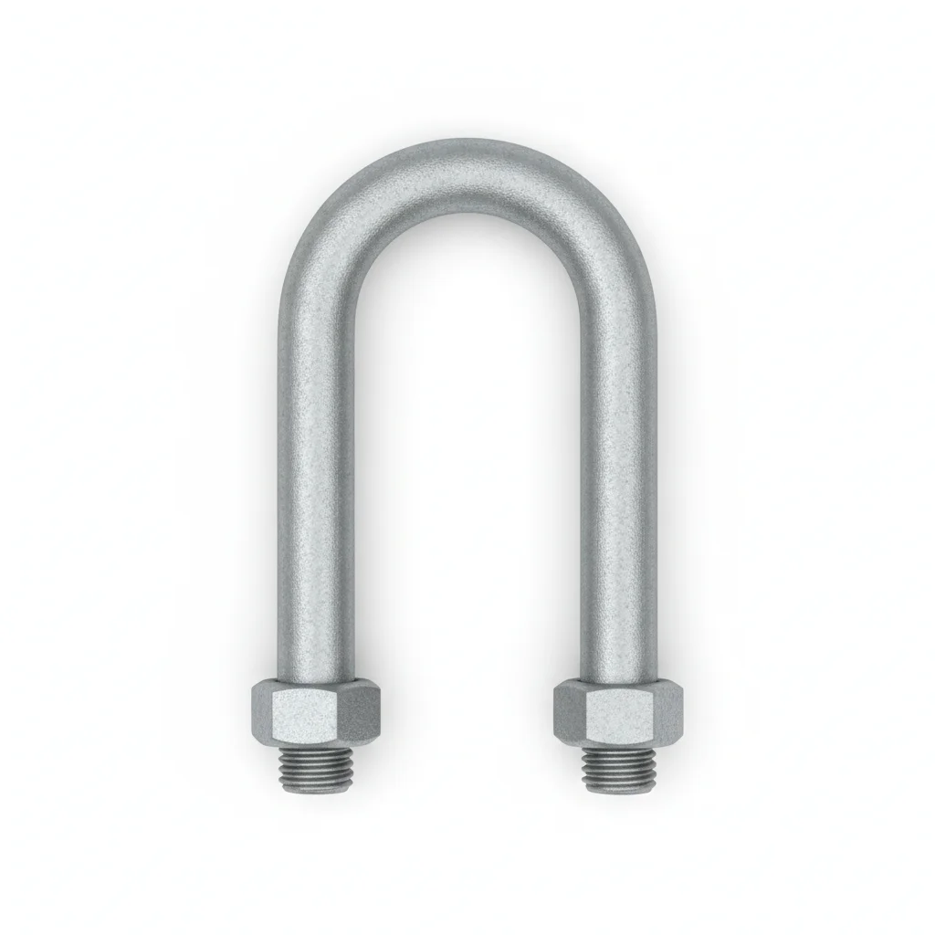
| Cast-in Anchor Bolt | U-Bolt | Anchor Bolt Cage | Leveling Shim | |
|---|---|---|---|---|
| SPEC | M20-M30, L-shaped/J-shaped/Straight | M16-M24 | Customized per design | 2-5mm stainless steel |
| MATERIAL | Grade 8.8 hot-dip galvanized/Dacromet | Hot-dip galvanized ≥65μm | Q235B hot-dip galvanized | 304 stainless steel |
| GRADE | Grade 8.8 | Grade 8.8 | — | — |
| FINISH | HDG, >=55um per ISO 1461 | HDG, >=55um per ISO 1461 | HDG, >=55um per ISO 1461 | HDG, >=55um per ISO 1461 |
| CORROSION | C3 (ISO 12944-2) | C3 (ISO 12944-2) | C3 (ISO 12944-2) | C3 (ISO 12944-2) |
| TEMP | -20°C to +80°C | -20°C to +80°C | -20°C to +80°C | -20°C to +80°C |
| WEIGHT | ~0.5 kg/piece | ~0.5 kg/piece | ~0.5 kg/piece | ~0.5 kg/piece |
| MOQ | 100 pcs | 100 pcs | 100 pcs | 100 pcs |
| PACK | VCI paper + carton | VCI paper + carton | VCI paper + carton | VCI paper + carton |
| STD | ISO 898-1, GB/T 3098.1 | ISO 898-1, GB/T 3098.1 | ISO 898-1, GB/T 3098.1 | ISO 898-1, GB/T 3098.1 |
| USE | Connection between foundation and mounting structure post | Fixing mounting structure posts on concrete foundation | Embedment in mass concrete | Adjustment of foundation top surface elevation |
PROCEDURE
- Prepare the foundation formwork and rebar cage, ensuring the cast-in anchor bolts (M20-M30, grade 8.8) are positioned accurately within the cage using templates.
- Align the anchor bolts to the specified verticality tolerance before pouring concrete; use leveling shims (2-5mm stainless steel) to fine-tune the top surface elevation after curing.
- Pour concrete and allow curing for at least 7 days before applying any load to the embedded bolts.
- After curing, attach the mounting structure post using U-bolts (M16-M24) and tighten with a calibrated torque wrench to the recommended torque for grade 8.8 fasteners.
- Apply a protective coating (epoxy or Dacromet) to the exposed threads and surfaces to meet the C4 corrosion class requirement.
COMMON ERRORS
| ✕ WRONG | CONSEQUENCE | ✓ CORRECT |
|---|---|---|
| Setting anchor bolts without a template, causing misalignment with the mounting structure holes. | Bolt holes may not align, requiring reaming or field modification, adding 20-30 minutes per foundation and potentially weakening the connection. | Use a rigid template to hold the anchor bolts in exact position during concrete pour, verifying alignment before and after pouring. |
| Tightening U-bolts before concrete has fully cured (less than 7 days). | Premature loading can crack the concrete or pull out the anchor bolts, reducing load capacity and compromising structural integrity. | Wait at least 7 days for concrete curing before installing and torquing the U-bolts. |
MAINTENANCE
Inspect anchor bolts and U-bolts for corrosion at each seasonal maintenance window, especially in coastal or industrial environments. Re-torque any fasteners that have loosened to the specified torque for grade 8.8. Check the coating thickness on exposed threads annually; if thinning exceeds 30%, apply a repair coating.
Plan C · Concrete Independent Foundation
C4 harsh environment per ISO 12944-2
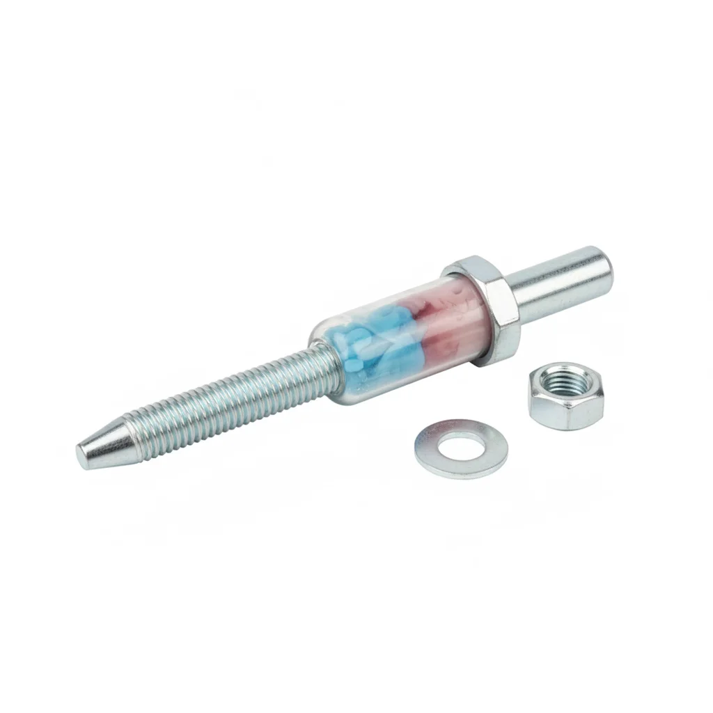
| U-Bolt | Foundation Reinforcement Cage | Cast-in Plate | Chemical Anchor | |
|---|---|---|---|---|
| SPEC | M20-M30 | Reinforcement per design | 20-30mm thick steel plate | M12-M20 |
| MATERIAL | Hot-dip galvanized ≥65μm | HRB400 | Q235B hot-dip galvanized | Carbon steel Dacromet |
| GRADE | Grade 8.8 | — | — | Grade 8.8/10.9 |
| FINISH | HDG, >=55um per ISO 1461 | HDG, >=55um per ISO 1461 | HDG, >=55um per ISO 1461 | HDG, >=55um per ISO 1461 |
| CORROSION | C3 (ISO 12944-2) | C3 (ISO 12944-2) | C3 (ISO 12944-2) | C3 (ISO 12944-2) |
| TEMP | -20°C to +80°C | -20°C to +80°C | -20°C to +80°C | -20°C to +80°C |
| WEIGHT | ~0.5 kg/piece | ~0.5 kg/piece | ~0.5 kg/piece | ~0.5 kg/piece |
| MOQ | 100 pcs | 100 pcs | 100 pcs | 100 pcs |
| PACK | VCI paper + carton | VCI paper + carton | VCI paper + carton | VCI paper + carton |
| STD | ISO 898-1, GB/T 3098.1 | ISO 898-1, GB/T 3098.1 | ISO 898-1, GB/T 3098.1 | ISO 898-1, GB/T 3098.1 |
| USE | Fixing posts on independent foundation | Reinforcement within concrete foundation | Connection plate at post base | Post-installed anchoring to existing concrete foundation |
PROCEDURE
- Excavate and prepare the foundation pit, then place the reinforcement cage (HRB400) and cast-in plate (20-30mm thick Q235B HDG) according to design drawings.
- Position the U-bolts (M20-M30, grade 8.8) through the cast-in plate, ensuring proper embedment depth and alignment.
- Pour concrete and allow curing for at least 14 days before applying any load to the foundation.
- After curing, mount the post onto the U-bolts and tighten to the specified torque using a calibrated wrench.
- Apply a protective coating (epoxy or Dacromet) to the exposed threads and connections to meet the C4 corrosion class requirement.
COMMON ERRORS
| ✕ WRONG | CONSEQUENCE | ✓ CORRECT |
|---|---|---|
| Using chemical anchors (M12-M20) in wet or uncured concrete, leading to poor adhesion. | Chemical anchors may not achieve the required pullout resistance, risking foundation failure under wind uplift loads. | Ensure concrete is fully cured (≥14 days) and dry before installing chemical anchors; follow the manufacturer's instructions for hole preparation and injection. |
| Neglecting to protect the cast-in plate and U-bolts from concrete splatter during pouring, causing corrosion later. | Concrete residue can trap moisture and accelerate corrosion, reducing the service life of the fasteners. | Cover the threads and exposed parts of the cast-in plate and U-bolts with protective tape or grease before pouring, and clean them thoroughly after. |
MAINTENANCE
Inspect all foundation bolts and plates at each seasonal maintenance window, especially after heavy storms. Re-torque any loosened fasteners to the specified torque. Check for corrosion on exposed surfaces and reapply protective coating if the HDG layer is damaged or thinning.
REFERENCED STANDARDS
Technical Basis and Reference Standards
"Design Standard for Photovoltaic Power Stations" (revised, effective 2025-04-01)
Design Qualification of Solar Trackers"Code for Structural Design of Photovoltaic Mounting Structures"
Code for Design of Building Foundation"Technical Code for Foundation of Solar Power Station Mounting Structures"
Geotechnical Engineering DesignHot-dip galvanized coatings on fabricated iron and steel articles - Technical conditions
GB/T 13912-2020Metallic coatings - Hot-dip galvanized coatings on fabricated iron and steel articles
SUPPLIER CAPABILITY
Quality, Delivery & Customization
Quality Control
- ✓MTC material certificates with every batch
- ✓Key parts sampled for hardness/salt spray/torque coefficient
- ✓100% inspection or AQL sampling before shipment
Delivery
- ✓Standard parts made to order: 7-15 days
- ✓Custom parts: 25-45 days
- ✓FOB/CIF/DDP supported
Customization
- ✓Drawing review and material matching
- ✓Non-standard sizes/heads/threads
- ✓Small-batch prototyping supported
Certification
- ✓Material certificates (MTC)
- ✓Spectrographic analysis reports
- ✓Salt spray test reports (on request)
MOQ: No MOQ for standard parts; custom parts assessed by process complexity
FAQ
Frequently Asked Questions
RELATED READING
Keep Reading & Next Step
BEYOND TECHNICAL SPECS
Finding the right factory, controlling quality, delivering on time — that's the real challenge. We cover fasteners, rubber, plastics, industrial textiles. One team, end to end.
SEE CAPABILITIES →