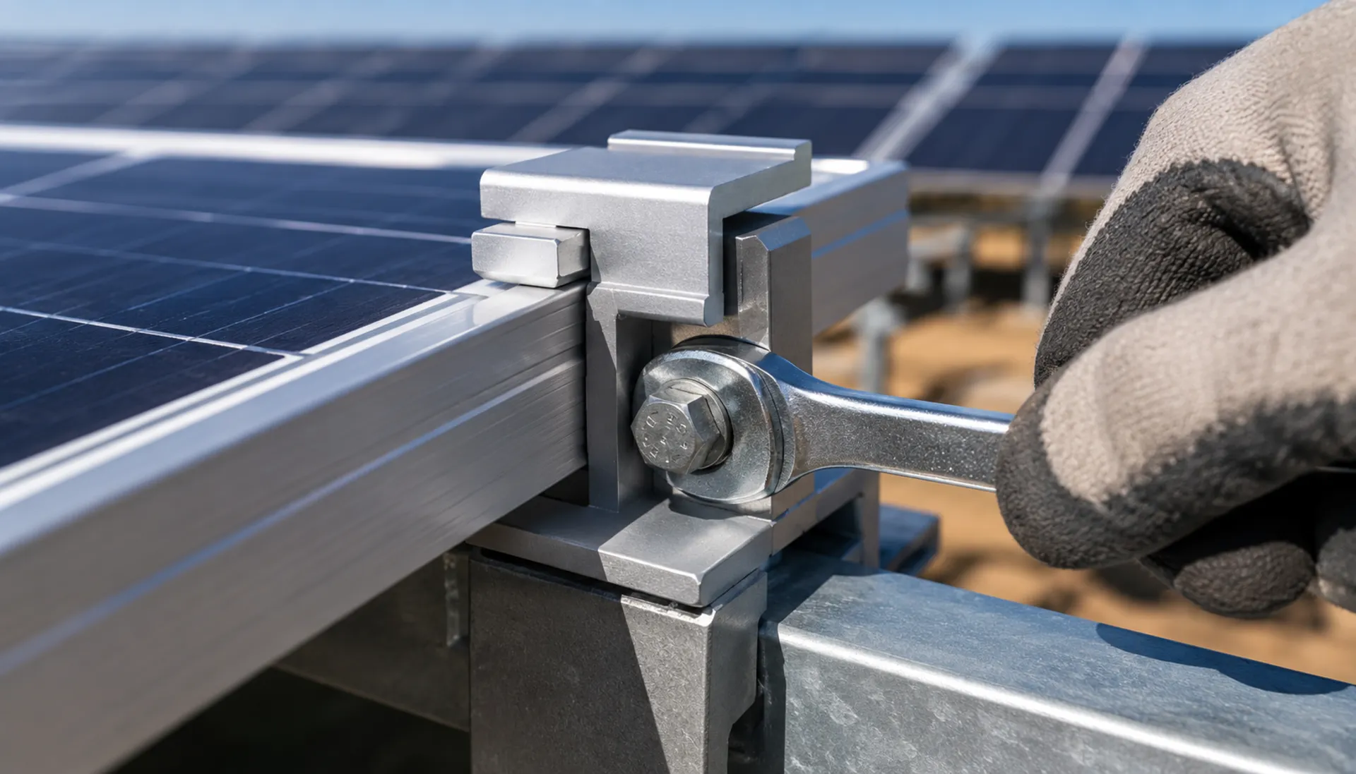
Solar Mounting Structure Fasteners: Material & Coating Comparison
Select the right bolt material and coating for your ground-mounted solar plant. Compare carbon steel + hot-dip galvanized, 304 stainless steel, and 316 stainless steel based on corrosion class, strength, and lifecycle. Includes torque coefficient control and thermal expansion considerations
RISK AUDIT // ENGINEERING DIAGNOSIS
Procurement Pitfall Avoidance Guide
"A clamp bolt that holds in May can back off by September — thermal cycling, lot-to-lot torque scatter, and coastal salt decide which joint lets go first."
QC-AUDIT // REV.5
SCALE 1:1 · 03 ITEMS
RISK-01
Bolt Torque Coefficient Fluctuation Leads to Preload Loss of Control
Corrective Measures
RISK-02
Lack of Slotted Holes in Long-Span Brackets Leads to Bolt Shearing from Thermal Expansion/Contraction
Corrective Measures
RISK-03
Large Hole Position Tolerance in Bracket Connectors Leads to On-Site Reaming and Rework
Corrective Measures
FIELD-SPECIFIC INSIGHT
3 Critical Checks for Solar Bracket Fastener Procurement
Beyond material grade, three factors often cause field failures: torque coefficient consistency, hole type for thermal movement, and hole position tolerance. These are not covered by standard material specs but directly affect preload, fatigue life, and installation schedule
WHAT TO CHECK
- 1Torque coefficient (k-value) must be controlled within ±0. 010 per batch
- 2Long-span brackets (>6m) require slotted holes to accommodate thermal expansion/contraction; round holes cause bolt shear fatigue in 2-3 years in desert climates
- 3Hole position tolerance >±2mm forces on-site reaming, reducing load area by 30-40%
| Check | Why it matters | What to specify |
|---|---|---|
| Torque coefficient consistency | Batch variation >±0. 010 causes preload scatter; under-torque leads to loosening, over-torque crushes washers | Require k-value test report per batch; target k=0. 20±0. 02 |
| Hole type for thermal expansion | Bolts shear under cyclic stress | Use slotted holes on one side of each span; specify slip allowance per EN 1993-1-8 |
| Hole position tolerance | Tolerance >±2mm causes misalignment; reaming reduces bolt shear capacity by 30-40% | Require dimensional inspection report |
| Coating thickness verification | Pitting initiates within 5 years | Specify HDG ≥65μm per ISO 1461; require magnetic thickness gauge report |
All values are based on typical engineering practice. Actual project requirements may vary; verify with structural engineer
Evidence level: source-page-only
INDUSTRY TECH REFERENCE
Four Breaking Points for Bracket Bolts: Risks and Fixes
Bracket bolts rarely fail for lack of static strength — fatigue, thermal movement, and corrosion fight them. Four critical breaking points:
| Risk | Key figures | Countermeasure |
|---|---|---|
| Transverse wind alternating shear | Fatigue limit at 10⁷ cycles ≈ 40-50% of static strength | Keep design stress within 60% of the fatigue limit (recommended) |
| Thermal expansion shears bolts | 80 m of racking moves about 72 mm over an 80-90°C swing | Add slotted sliding joints every 20-30 m (recommended) |
| Coating too thin for the site | GB/T 13912 tiers — bracket bolts start at ≥70 μm | Step up to Dacromet or 304 near the coast |
| Stress-corrosion cracking (SCC) | Neck rust is the earliest warning sign | Inspect before every winter; replace the bolt outright |
"About" figures trace to the KB (not estimates); the 60% design cap and 20-30 m joint spacing are recommended values.
INDUSTRY TECH REFERENCE
The Bracket Bolt Fracture Chain: Fatigue Meets Thermal Stress
Bracket bolts break not from static overload, but from alternating shear and thermal stress stacking up.
- 1The whole load path — post → beam → purlin → module — rides on M10-M20 HDG bolts under alternating shear from transverse wind
- 2After 10⁷ cycles the fatigue limit falls to 40-50% of static strength — keep design stress within 60% of that limit (recommended)
- 3An 80-90°C swing moves 80 m of racking about 72 mm; the slotted sliding joint is the only release path
- 4Lock every connection and the thermal stress lands on the bolts — alternating stress stacks up and fracture comes early
- 5Before each winter, check the bolt necks: rust is an SCC sign — replace the bolt outright, never weld or patch
The 40-50% fatigue ratio and 72 mm movement are KB-sourced (not estimates); the 60% cap and inspection cadence are recommendations.
INDUSTRY TECH REFERENCE
Bracket Bolts: Procurement and Incoming Inspection
Bulk project procurement with material tiered by corrosion environment — three checks at goods-in:
- Full-chain size M10-M20, mostly hot-dip galvanized — a 100 MW plant needs about 500-800k pieces (magnitude estimate)
- Tier material by site: inland per GB/T 13912 tiers from ≥70 μm; coastal steps up to Dacromet or 304
- Inspect thread coating and necks lot by lot: rust at the neck is an SCC sign — reject or replace the bolt outright
"About 500-800k pieces per 100 MW" is a magnitude estimate.
INDUSTRY TECH REFERENCE
Standards for Bracket Design and Coating Acceptance
Reference these standards when specifying and accepting:
Standards listed for navigation; acceptance criteria per the official texts.
PLAN COMPARISON
Three-Plan Core Parameter Comparison
Compare row by row. Click column headers to jump to plan details.
| A · Plan A · Economical | B · Plan B · High Weather Resistance | C · Plan C · Advanced Corrosion Protection | |
|---|---|---|---|
| 1. HEX HEAD BOLT | |||
| SPEC | M8×25 ~ M16×60 | M8×25 ~ M16×60 | M10×30 ~ M20×80 |
| MATERIAL | Carbon Steel + Hot-Dip Galvanized (≥65μm) | 304 Stainless Steel (A2-70) | 316 Stainless Steel (A4-80) |
| GRADE | Grade 8.8 | Grade 70 | Grade 80 |
| FINISH | HDG >=55um per ISO 1461 | HDG >=55um per ISO 1461 | HDG >=55um per ISO 1461 |
| 2. SOCKET HEAD CAP SCREW | |||
| SPEC | M6×20 ~ M12×40 | M6×20 ~ M12×40 | Customized as required |
| MATERIAL | Carbon Steel + Hot-Dip Galvanized | 304 Stainless Steel | Carbon Steel + Hot-Dip Plastic (PE/PA) |
| GRADE | Grade 8.8 | A2-70 | 8.8/10.9 |
| FINISH | HDG >=55um per ISO 1461 | HDG >=55um per ISO 1461 | HDG >=55um per ISO 1461 |
| 3. ALUMINUM MID CLAMP BLOCK | |||
| SPEC | Length 50mm | Length 50mm | Length 60mm |
| MATERIAL | 6063-T5 + Anodized | 304 Stainless Steel | 316 Stainless Steel |
| FINISH | HDG >=55um per ISO 1461 | HDG >=55um per ISO 1461 | HDG >=55um per ISO 1461 |
| 4. ALUMINUM END CLAMP BLOCK | |||
| SPEC | Length 50mm | M10×30 ~ M16×50 | Length 60mm |
| MATERIAL | 6063-T5 + Anodized | Carbon Steel + Dacromet Coating | 316 Stainless Steel |
| GRADE | — | Grade 10.9 | — |
| FINISH | HDG >=55um per ISO 1461 | HDG >=55um per ISO 1461 | HDG >=55um per ISO 1461 |
Plan A · Economical
C3 per ISO 12944-2; coastal <3km and offshore salt-spray sites step up to Grade 70 / duplex 2205 hardware
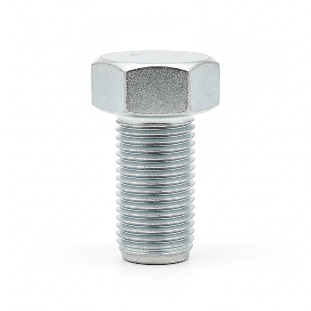
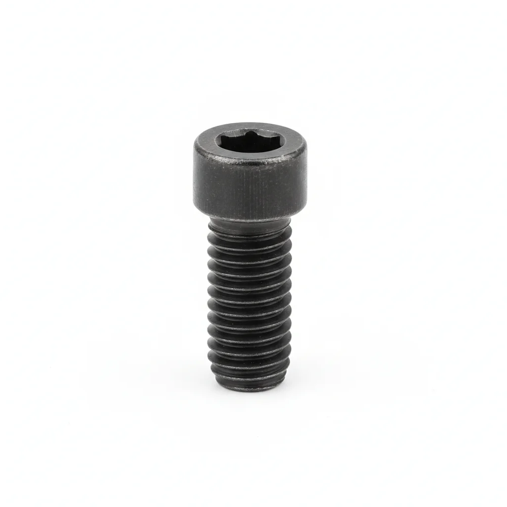
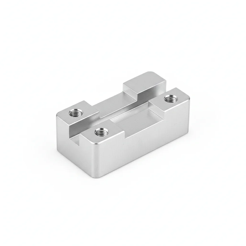
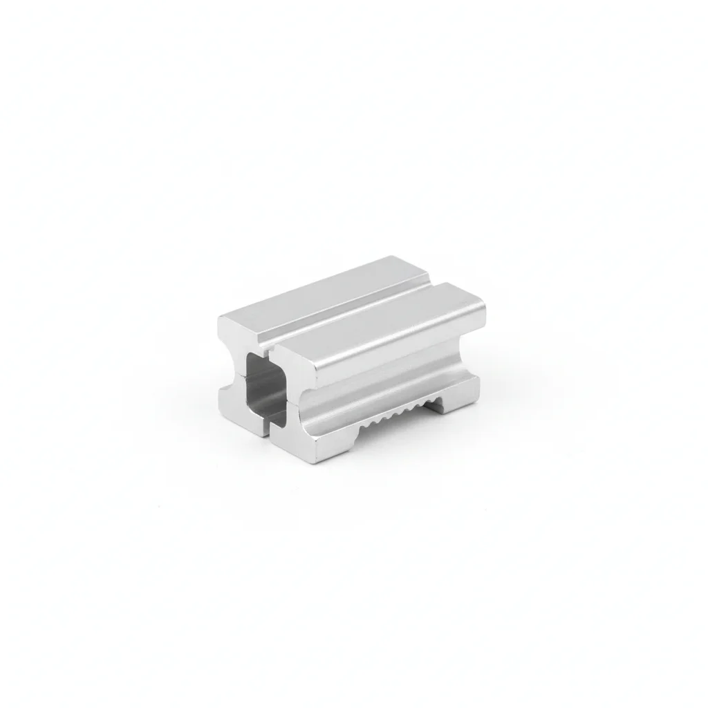
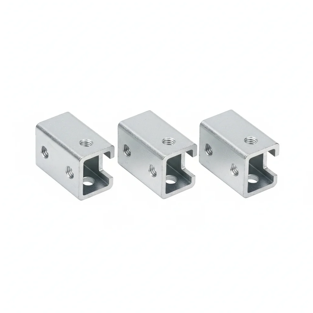
| Hex Head Bolt | Socket Head Cap Screw | Aluminum Mid Clamp Block | Aluminum End Clamp Block | Rail Connector | |
|---|---|---|---|---|---|
| SPEC | M8×25 ~ M16×60 | M6×20 ~ M12×40 | Length 50mm | Length 50mm | Compatible with C-channel rail |
| MATERIAL | Carbon Steel + Hot-Dip Galvanized (≥65μm) | Carbon Steel + Hot-Dip Galvanized | 6063-T5 + Anodized | 6063-T5 + Anodized | Q235B Hot-Dip Galvanized |
| GRADE | Grade 8.8 | Grade 8.8 | — | — | — |
| FINISH | HDG >=55um per ISO 1461 | HDG >=55um per ISO 1461 | HDG >=55um per ISO 1461 | HDG >=55um per ISO 1461 | HDG >=55um per ISO 1461 |
| CORROSION | C3 (ISO 12944-2) | C3 (ISO 12944-2) | C3 (ISO 12944-2) | C3 (ISO 12944-2) | C3 (ISO 12944-2) |
| TEMP | -20°C to +80°C | -20°C to +80°C | -20°C to +80°C | -20°C to +80°C | -20°C to +80°C |
| WEIGHT | ~0.5 kg/piece | ~0.5 kg/piece | ~0.5 kg/piece | ~0.5 kg/piece | ~0.5 kg/piece |
| MOQ | 100 pcs | 100 pcs | 100 pcs | 100 pcs | 100 pcs |
| PACK | VCI paper + carton | VCI paper + carton | VCI paper + carton | VCI paper + carton | VCI paper + carton |
| STD | ISO 898-1, GB/T 3098.1 | ISO 898-1, GB/T 3098.1 | ISO 898-1, GB/T 3098.1 | ISO 898-1, GB/T 3098.1 | ISO 898-1, GB/T 3098.1 |
| USE | Main bracket connection | Module and rail fixing | Module center fixing | Array edge fixing | Rail splicing |
PROCEDURE
- Lay out C-channel rails per the racking drawing; keep the slotted holes in long-span bracket joints free so thermal expansion does not buckle the rail.
- Fix rail connectors with hex head bolts M8×25 to M16×60, grade 8.8 hot-dip galvanized per EN ISO 10684; engage full thread and seat washers flat against the rail.
- Clamp modules with the aluminum mid/end clamp blocks (50mm); tighten socket head cap screws M6×20 to M12×40 evenly, working from the array center outward.
- Torque with a calibrated wrench only; verify the lot torque coefficient before tensioning — scatter stays within standard deviation 0.010 per GB 50205.
- Mark each tightened bolt with a witness line and record lot number and torque value on the array map for later audit.
COMMON ERRORS
| ✕ WRONG | CONSEQUENCE | ✓ CORRECT |
|---|---|---|
| Mixing grade 8.8 HDG bolts with plain black bolts of the same size from site stock. | In coastal air the black bolts rust first; crevice corrosion at the rail interface undercuts the coating of adjacent galvanized parts and the joint loosens in the first storm season. | Segregate fasteners by plan grade and coating; within 3km of coastline or offshore, use Grade 70 stainless or duplex 2205 hardware only. |
| Re-drilling bracket holes on site to force misaligned rails to fit. | Re-drilled holes remove the slotted allowance for thermal expansion; summer heat buckles the rail, popping module clamps and cracking glass. | Use the designed slotted holes; if hole position tolerance is exceeded, replace the bracket rather than modify it. |
| Driving clamp screws with an impact wrench to save time. | Impact torque overshoots and strips the aluminum rail channel; torque scatter doubles, so the same tool setting gives different preload per bolt. | Use a calibrated torque wrench only — impact tools are banned for PV clamp bolts. |
MAINTENANCE
After the first storm season, re-check clamp bolt torque on a sample per array and re-torque any bolt below the lot setpoint. Annually inspect rail connectors and bracket interfaces for white rust on HDG parts (per ISO 1461) and pitting on stainless parts; at coastal sites within 3km shorten the interval per plan B. Replace any clamp block showing deformation, and keep the witness-line record current for warranty audits.
Plan B · High Weather Resistance
C4 Harsh per ISO 12944-2
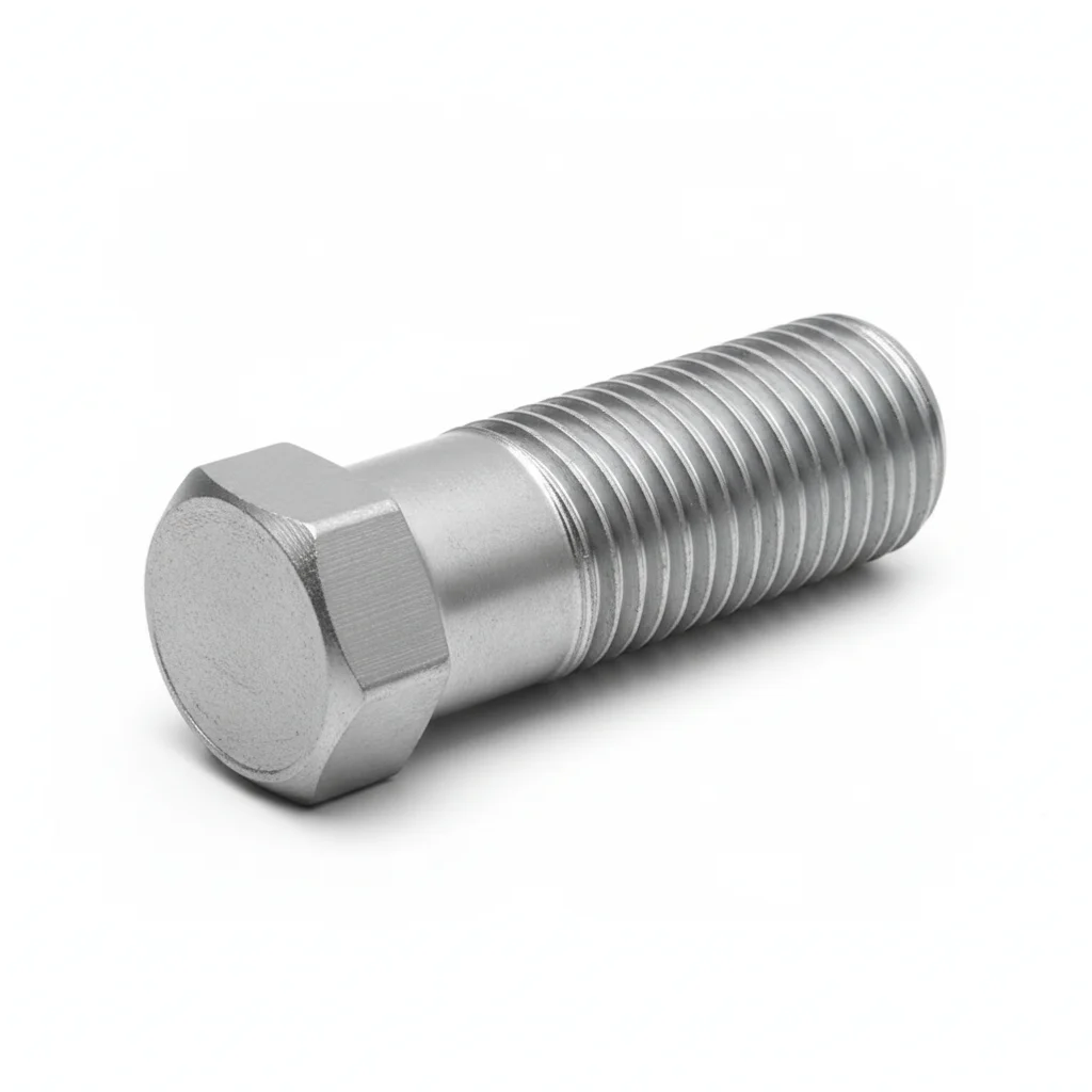
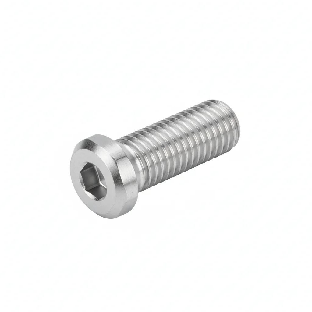
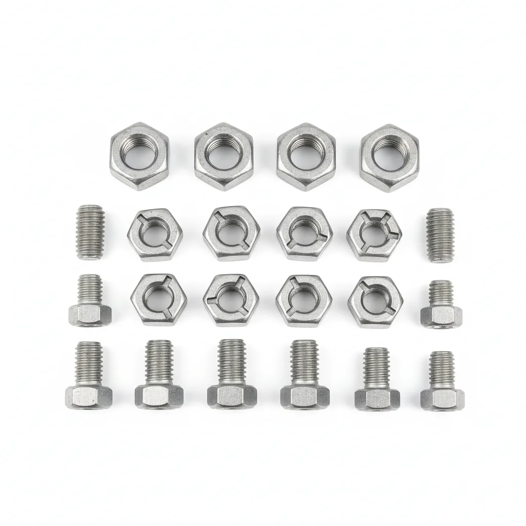
| Hex Head Bolt | Socket Head Cap Screw | Mid Clamp Block | Dacromet Bolt | Aluminum Mid Clamp Block | |
|---|---|---|---|---|---|
| SPEC | M8×25 ~ M16×60 | M6×20 ~ M12×40 | Length 50mm | M10×30 ~ M16×50 | Length 50mm |
| MATERIAL | 304 Stainless Steel (A2-70) | 304 Stainless Steel | 304 Stainless Steel | Carbon Steel + Dacromet Coating | 6063-T5 + Anodized |
| GRADE | Grade 70 | A2-70 | — | Grade 10.9 | — |
| FINISH | HDG >=55um per ISO 1461 | HDG >=55um per ISO 1461 | HDG >=55um per ISO 1461 | HDG >=55um per ISO 1461 | HDG >=55um per ISO 1461 |
| CORROSION | C3 (ISO 12944-2) | C3 (ISO 12944-2) | C3 (ISO 12944-2) | C3 (ISO 12944-2) | C3 (ISO 12944-2) |
| TEMP | -20°C to +80°C | -20°C to +80°C | -20°C to +80°C | -20°C to +80°C | -20°C to +80°C |
| WEIGHT | ~0.5 kg/piece | ~0.5 kg/piece | ~0.5 kg/piece | ~0.5 kg/piece | ~0.5 kg/piece |
| MOQ | 100 pcs | 100 pcs | 100 pcs | 100 pcs | 100 pcs |
| PACK | VCI paper + carton | VCI paper + carton | VCI paper + carton | VCI paper + carton | VCI paper + carton |
| STD | ISO 898-1, GB/T 3098.1 | ISO 898-1, GB/T 3098.1 | ISO 898-1, GB/T 3098.1 | ISO 898-1, GB/T 3098.1 | ISO 898-1, GB/T 3098.1 |
| USE | Main bracket connection | Module fixing | Module fixing in high corrosion areas | High strength + corrosion resistance | Usable in regular areas |
PROCEDURE
- Clean threads and bearing surfaces with a lint-free cloth dipped in acetone to remove any residual machining oil or debris before assembly.
- For 304 stainless steel fasteners, apply a molybdenum disulfide-based anti-seize compound to threads to prevent galling during tightening.
- For Dacromet-coated bolts (Grade 10.9), verify coating integrity—no bare metal spots—and handle with clean gloves to avoid contaminating the coating.
- Tighten in a cross-pattern sequence with a calibrated torque wrench; for the Dacromet bolts, follow the torque values specified for Grade 10.9 to achieve proper preload without over-stressing.
- After installation, mark each bolt head with a torque seal paint line to allow visual verification of any loosening during subsequent inspections.
COMMON ERRORS
| ✕ WRONG | CONSEQUENCE | ✓ CORRECT |
|---|---|---|
| Mixing 304 stainless steel bolts with carbon steel washers or nuts | Galvanic corrosion at the contact point can rapidly degrade the stainless steel, leading to premature failure in the humid, coastal-influenced environment. | Ensure all mating components (bolts, nuts, washers) are of the same 304 stainless steel grade or use isolation washers to prevent bimetallic contact. |
| Using an impact wrench on Dacromet-coated Grade 10.9 bolts | Impact tools deliver uncontrolled torque spikes that can exceed the bolt's proof load, causing yielding or fracture, and the Dacromet coating may chip, exposing bare steel to corrosion. | Tighten with a slow-speed, calibrated torque wrench, and never exceed the specified torque range for Grade 10.9 fasteners. |
MAINTENANCE
Perform visual inspections at each seasonal maintenance cycle, focusing on coastal or industrial areas for any signs of rust or discoloration. For Dacromet-coated bolts, check for coating damage (scratches or chips) that could expose the carbon steel substrate. If any corrosion is found on more than 5% of the surface area, replace the fastener immediately. Verify torque security on a sample of bolts annually, especially after high-wind events, and re-torque any that have loosened below the specified value.
Plan C · Advanced Corrosion Protection
C5-M Extreme per ISO 12944-2
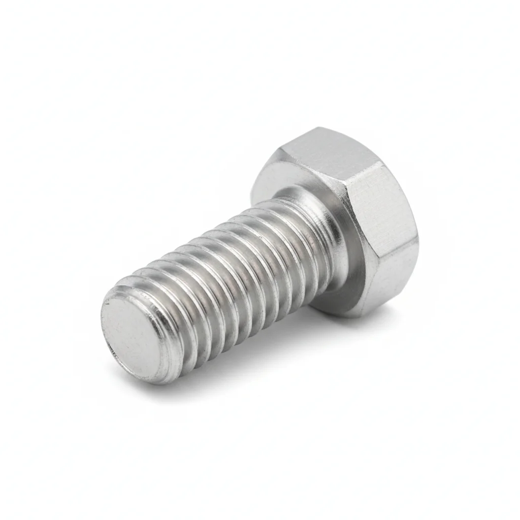
| Hex Head Bolt | Hot-Dip Plastic Coated Bolt | Clamp Block | End Clamp Block | |
|---|---|---|---|---|
| SPEC | M10×30 ~ M20×80 | Customized as required | Length 60mm | Length 60mm |
| MATERIAL | 316 Stainless Steel (A4-80) | Carbon Steel + Hot-Dip Plastic (PE/PA) | 316 Stainless Steel | 316 Stainless Steel |
| GRADE | Grade 80 | 8.8/10.9 | — | — |
| FINISH | HDG >=55um per ISO 1461 | HDG >=55um per ISO 1461 | HDG >=55um per ISO 1461 | HDG >=55um per ISO 1461 |
| CORROSION | C3 (ISO 12944-2) | C3 (ISO 12944-2) | C3 (ISO 12944-2) | C3 (ISO 12944-2) |
| TEMP | -20°C to +80°C | -20°C to +80°C | -20°C to +80°C | -20°C to +80°C |
| WEIGHT | ~0.5 kg/piece | ~0.5 kg/piece | ~0.5 kg/piece | ~0.5 kg/piece |
| MOQ | 100 pcs | 100 pcs | 100 pcs | 100 pcs |
| PACK | VCI paper + carton | VCI paper + carton | VCI paper + carton | VCI paper + carton |
| STD | ISO 898-1, GB/T 3098.1 | ISO 898-1, GB/T 3098.1 | ISO 898-1, GB/T 3098.1 | ISO 898-1, GB/T 3098.1 |
| USE | Critical structural connection | Buried or underwater installation | Dedicated for offshore solar | Array edge fixing |
PROCEDURE
- Degrease all fastener components with MEK solvent and allow to fully evaporate; verify surface roughness of mating parts is below Ra 1.6μm for optimal sealing.
- For 316 stainless steel (A4-80) bolts, apply a marine-grade anti-seize compound containing molybdenum disulfide to threads and under the bolt head to prevent galling in salt-laden environments.
- For hot-dip plastic-coated bolts intended for buried or underwater use, inspect the plastic layer for any pinholes or damage; repair with an approved sealant if necessary before installation.
- Tighten fasteners using a calibrated torque wrench in a cross-pattern sequence. For critical structural connections, use a hydraulic tensioner to achieve precise preload control, and verify with a torque-audit on 10% of the installed bolts.
- After tightening, apply a protective sealant over the bolt head and nut to create a moisture barrier, and install a corrosion monitoring coupon near critical joints to track environmental aggressiveness.
COMMON ERRORS
| ✕ WRONG | CONSEQUENCE | ✓ CORRECT |
|---|---|---|
| Substituting 304 stainless steel fasteners for 316 in critical offshore connections | 304 has lower resistance to chloride pitting; in a high salt-spray environment, pitting can initiate within months, leading to stress corrosion cracking and sudden fastener failure. | Verify that all fasteners in critical offshore or chemical plant areas are clearly marked as 316 or A4-80 grade; do a PMI (positive material identification) test on a sample to confirm composition. |
| Over-tightening hot-dip plastic-coated bolts | Excessive torque can crack or delaminate the plastic coating, exposing the carbon steel core to corrosive elements, which leads to rapid rusting and loss of structural integrity. | Use a torque wrench set to the manufacturer's specified value for plastic-coated bolts, and avoid using impact tools that can damage the coating. |
MAINTENANCE
Inspect fasteners at every overhaul window or seasonally, whichever is more frequent, focusing on areas with visible salt deposits or chemical exposure. Use a dye penetrant test on a 10% sample of critical structural bolts annually to detect any micro-cracks. Replace any fastener showing pitting depth greater than 0.3mm or corrosion affecting more than 5% of its surface area. For plastic-coated bolts, check for coating integrity; any damage must be repaired or the bolt replaced. Record all inspection results and corrective actions in the maintenance log for compliance audits.
SELECTION GUIDE
Which bracket hardware class matches your site's corrosion category?
| Operating condition | Recommended option | Key basis |
|---|---|---|
| Check project site corrosion level (inland vs coastal) | Assess per ISO 9223; coastal <3km and offshore salt-spray sites step up to Grade 70 / duplex 2205 hardware | ISO 9223, ISO 12944-2 |
| Cost priority, design life 20 years, corrosion ≤C3 | Plan A Economical: carbon steel + hot-dip galvanized ≥65μm, Grade 8.8 (lowest cost) | ISO 12944-2 C3, ISO 1461 (≥65μm) |
| Design life 25 years, coastline <3km / industrial pollution / annual humidity >80% | Plan B High Weather Resistance: 304 SS (A2-70) or Dacromet-coated carbon steel Grade 10.9 (cost +15-25%) | ISO 12944-2 C4, EN 1993-1-8 (A2-70) |
| Design life >30 years, offshore / chemical plant (cost +40-60%) | Plan C Advanced Corrosion Protection: 316 SS (A4-80), 2-3% Mo, chloride pitting resistance >3x that of 304 | ISO 12944-2 C5-M, EN 1993-1-8 (A4-80) |
REFERENCED STANDARDS
Technical Basis and Reference Standards
Mechanical properties of fasteners — Bolts, screws and studs
Design Qualification of Solar TrackersFasteners — Hot dip galvanized coatings
Standard for Design of Steel StructuresCorrosion of metals and alloys — Classification of atmospheric corrosivity
Design of Joints in Steel StructuresMechanical properties of stainless steel fasteners (A2-70/A4-80)
NB/T 10115-2018Design Specification for Photovoltaic Support Structures
ISO 1461Hot dip galvanized coatings on fabricated iron and steel articles — ≥65μm life basis
SUPPLIER CAPABILITY
Quality, Delivery & Customization
Quality Control
- ✓MTC material certificates with every batch
- ✓Key parts sampled for hardness/salt spray/torque coefficient
- ✓100% inspection or AQL sampling before shipment
Delivery
- ✓Standard parts made to order: 7-15 days
- ✓Custom parts: 25-45 days
- ✓FOB/CIF/DDP supported
Customization
- ✓Drawing review and material matching
- ✓Non-standard sizes/heads/threads
- ✓Small-batch prototyping supported
Certification
- ✓Material certificates (MTC)
- ✓Spectrographic analysis reports
- ✓Salt spray test reports (on request)
MOQ: No MOQ for standard parts; custom parts assessed by process complexity
FAQ
Frequently Asked Questions
RELATED READING
Keep Reading & Next Step
NEXT: SELECTION & RFQ
PV Electrical ConnectorsFollow this page's selection path to the same-scenario RFQ page.
BEYOND TECHNICAL SPECS
Finding the right factory, controlling quality, delivering on time — that's the real challenge. We cover fasteners, rubber, plastics, industrial textiles. One team, end to end.
SEE CAPABILITIES →