
PV Grounding Clamp Material Comparison: 304 vs 316 vs 316L
Poor grounding is a 'silent killer' in PV power stations. The grounding clamp material directly impacts contact resistance and corrosion resistance. This page compares 304, 316, and 316L stainless steel grounding clamps for different environments (C3 inland, C4 coastal, C5 offshore) and lightning protection levels, with a focus on avoiding galvanic corrosion and ensuring reliable lightning current path
RISK AUDIT // ENGINEERING DIAGNOSIS
Procurement Pitfall Avoidance Guide
"In PV plants, a seemingly intact clamp can hide a broken grounding path."
QC-AUDIT // REV.5
SCALE 1:1 · 03 ITEMS
RISK-01
Poor contact between grounding clamp and module frame causes lightning damage
Corrective Measures
RISK-02
Galvanic corrosion at copper-aluminum contact surface causes grounding disconnection
Corrective Measures
RISK-03
Insufficient cross-section of grounding braid leads to inadequate lightning current carrying capacity
Corrective Measures
FIELD-SPECIFIC INSIGHT
Grounding Clamp Selection: 3 Critical Checks for PV Engineers
The anodized layer on aluminum module frames (Al₂O₃, an insulator) prevents metal-to-metal contact. Ordinary grounding clamps relying on spring force cannot penetrate this layer, leading to high contact resistance and arcing under lightning current. Spiked teeth or serrated washers are required to pierce the oxide layer. Additionally, copper-aluminum galvanic corrosion (potential difference ~2V) can cause grounding disconnection within 1-2 years in humid environments. The table below summarizes key selection criteria
WHAT TO CHECK
- 1Spiked teeth or serrated washers: Must penetrate Al₂O₃ layer on module frame to achieve metal-to-metal contact; without this, contact resistance remains high
- 2Material compatibility: 304 SS for C3 inland; 316 SS for C4 coastal; 316L for C5 offshore/offshore to avoid galvanic corrosion with aluminum frame
- 3Cross-section of copper braid: Minimum 6mm² for standard, 16mm² for Class I lightning protection per IEC 62305-3; undersized braid melts under 100kA lightning current
- 4Torque specification: Insufficient tightening torque of mounting bolt increases contact resistance; re-torque to specified value during installation and maintenance
| Check | Why it matters | What to specify |
|---|---|---|
| Contact surface preparation | Al₂O₃ layer on frame is an insulator; without penetration, contact resistance is high, leading to arcing under lightning | Use grounding clamps with spiked teeth or serrated washers; specify 'penetrate anodized coating' in installation instructions |
| Material selection for environment | Galvanic corrosion between copper braid and aluminum frame (potential difference ~2V) causes white corrosion and disconnection | For C3: 304 SS; for C4: 316 SS; for C5: 316L; apply conductive paste (copper-based or silver-based) to contact surfaces |
| Copper braid cross-section | Undersized braid melts under lightning current, disconnecting the grounding path | Minimum 6mm² for standard, 16mm² for Class I lightning protection per IEC 62305-3; verify with supplier test report |
| Torque and maintenance | Loose bolts increase contact resistance; corrosion reduces clamping force over time | Specify torque value in installation manual; inspect every 6 months; re-torque if below 80% of specified torque; replace if corrosion >5% surface area |
All grounding clamps must comply with UL 467 or equivalent. For export to EU/US, DNV or UL certification may be required. Contact resistance should be verified with a micro-ohmmeter after installation
Evidence level: source-page-only
INDUSTRY TECH REFERENCE
Why Grounding Failure Only Surfaces in a Lightning Strike
Walking the toothed grounding clamp path — frame → racking → grid, with the link breaking at tooth penetration.
- 1The anodized layer on aluminum frames is an insulator — teeth must pierce it to open the frame → racking → grid path
- 2Worn or unseated teeth raise joint resistance — investigate any point above 10 Ω (distinct from the array-level target)
- 3Pre-storm-season full-array test: array resistance must meet ≤4 Ω (GB 50169) — a poor path only shows up when lightning strikes
- 4On a strike, voltage surges across the high-impedance point → insulation breakdown / arcing — grounding failures are the most hidden kind
- 5Countermeasure: focus this test round on whether the toothed washer still pierces the anodized layer — tooth condition is where trouble starts
The ≤4 Ω array target and >10 Ω point threshold are traced (GB 50169 / KB inspection threshold), not estimates.
INDUSTRY TECH REFERENCE
Grounding Parts and Cable Clamps: Specs and Volumes
Per-project volumes and acceptance checks for the two hardware lines — pin each down at ordering and goods-in.
| Part | Material / size | Per-project volume | Acceptance check |
|---|---|---|---|
| Toothed grounding part (clamp/washer) | 304 + copper piercing tip, M6-M8 | Tens of thousands per 100 MW (magnitude estimate) | Array ground resistance ≤4 Ω (GB 50169) |
| Cable clamp | 304/PA66, φ4-8 mm | Thousands per MW (magnitude estimate) | Clamp spacing ≤500 mm (recommended); stainless clamps at critical runs |
| Full-array test node | — | — | Full-array test before every storm season; check tooth penetration into the anodized layer |
Per-project volumes are magnitude estimates; ≤500 mm clamp spacing is recommended.
INDUSTRY TECH REFERENCE
Grounding Checkup Before the Storm Season
Grounding faults stay invisible in routine checks — the pre-storm-season round is the first line of defense.
- Accept the array at ≤4 Ω (GB 50169) — when it fails, locate point by point before replacing anything
- Investigate any joint above 10 Ω, measuring point by point with a milliohm meter; start with the clamp-to-frame contact face
- Full-array test before every storm season — confirm the toothed washer/clamp still pierces the anodized layer; tooth penetration is the focus of this round
- Inspect ground straps and clamps twice a year — stainless clamps at critical runs (recommended)
- IR-scan straps and cable runs for local hot spots — local heating mostly means rising contact resistance
≤4 Ω / >10 Ω are traced thresholds; inspection cadence and stainless-clamp runs follow the KB scheme (recommended).
PLAN COMPARISON
Three-Plan Core Parameter Comparison
Compare row by row. Click column headers to jump to plan details.
| A · Plan A · Standard Grounding Configuration | B · Plan B · Enhanced Lightning Protection Configuration | C · Plan C · Extreme Environment / Regulatory Compliance | |
|---|---|---|---|
| 1. W-TYPE GROUNDING CLAMP | |||
| SPEC | For 6mm² ground wire | For 10mm² ground wire | For 16mm² ground wire |
| MATERIAL | 304 Stainless Steel with Spiked Teeth | 316 Stainless Steel with Spiked Teeth | 316L Stainless Steel Electropolished |
| GRADE | UL 467 | UL 467+DNV | UL 467+DNV GL |
| FINISH | HDG >=55um per ISO 1461 | HDG >=55um per ISO 1461 | HDG >=55um per ISO 1461 |
| 2. RAIL GROUNDING CLAMP | |||
| SPEC | For C-channel rail | For C-channel rail | For C-channel + frame + ground wire |
| MATERIAL | 304 Stainless Steel | 316 Stainless Steel | 316L Stainless Steel |
| GRADE | UL 467 | UL 467 | IP68 |
| FINISH | HDG >=55um per ISO 1461 | HDG >=55um per ISO 1461 | HDG >=55um per ISO 1461 |
| 3. MODULE FRAME GROUNDING CLAMP | |||
| SPEC | For 30-50mm frame | For 30-50mm frame | 16mm² Silver-plated |
| MATERIAL | 304 Stainless Steel with Teeth | 316 Stainless Steel with Teeth | T2 Copper Silver-plated |
| GRADE | UL 467 | UL 467 | IEC 62305 |
| FINISH | HDG >=55um per ISO 1461 | HDG >=55um per ISO 1461 | HDG >=55um per ISO 1461 |
| 4. COPPER BRAID GROUNDING STRAP | |||
| SPEC | 6mm² Tin-plated | 16mm² Tin-plated | 50g/tube |
| MATERIAL | T2 Copper Tin-plated | T2 Copper Tin-plated | Silver-Based Conductive Paste |
| GRADE | IEC 62305 | IEC 62305 Class I Lightning Protection | Contact resistance <1μΩ·cm² |
| FINISH | HDG >=55um per ISO 1461 | HDG >=55um per ISO 1461 | HDG >=55um per ISO 1461 |
| 5. BRASS GROUNDING TERMINAL | |||
| SPEC | M6/M8/M10 | 100g/tube | M6-M10 |
| MATERIAL | Brass | Copper-Based Conductive Paste | 316L Stainless Steel |
| GRADE | Tin-plated | Contact resistance <5μΩ·cm² | Electropolished |
| FINISH | HDG >=55um per ISO 1461 | HDG >=55um per ISO 1461 | HDG >=55um per ISO 1461 |
SELECTION GUIDE
Not sure which to choose?
| Operating condition | Recommended option | Key basis |
|---|---|---|
| Ordinary inland site, C3 (ISO 12944-2), wind <25m/s | Plan A Standard Grounding: 304 SS spiked-teeth grounding clamp + 6mm² tin-plated copper braid | UL 467 (contact resistance <0.01Ω), IEC 62305, ISO 12944-2 C3 |
| Large station >1MW / high lightning area / coastal C4-C5 | Plan B Enhanced Lightning Protection: 316 SS spiked-teeth clamp + 16mm² tin-plated copper braid (Class I lightning protection) | IEC 62305-3 Class I, UL 467, ISO 12944-2 C4-C5 |
| Offshore / export requiring DNV/UL dual certification | Plan C Extreme: 316L electropolished clamp + 16mm² silver-plated copper braid + silver-based conductive paste | DNV GL, UL 467, IEC 62305, ISO 3506-1:2020 |
Plan A · Standard Grounding Configuration
C3 inland per ISO 12944-2
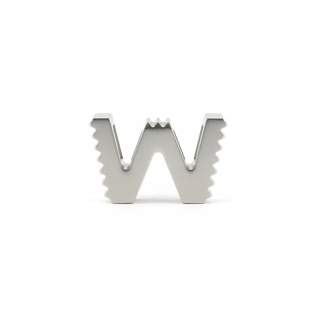
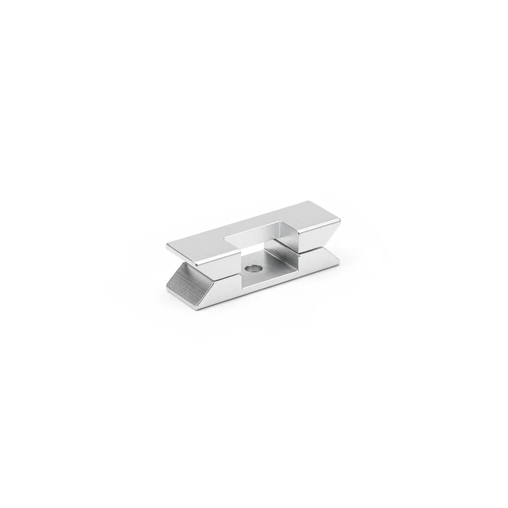
| W-Type Grounding Clamp | Rail Grounding Clamp | Module Frame Grounding Clamp | Copper Braid Grounding Strap | Brass Grounding Terminal | |
|---|---|---|---|---|---|
| SPEC | For 6mm² ground wire | For C-channel rail | For 30-50mm frame | 6mm² Tin-plated | M6/M8/M10 |
| MATERIAL | 304 Stainless Steel with Spiked Teeth | 304 Stainless Steel | 304 Stainless Steel with Teeth | T2 Copper Tin-plated | Brass |
| GRADE | UL 467 | UL 467 | UL 467 | IEC 62305 | Tin-plated |
| FINISH | HDG >=55um per ISO 1461 | HDG >=55um per ISO 1461 | HDG >=55um per ISO 1461 | HDG >=55um per ISO 1461 | HDG >=55um per ISO 1461 |
| CORROSION | C3 (ISO 12944-2) | C3 (ISO 12944-2) | C3 (ISO 12944-2) | C3 (ISO 12944-2) | C3 (ISO 12944-2) |
| TEMP | -20°C to +80°C | -20°C to +80°C | -20°C to +80°C | -20°C to +80°C | -20°C to +80°C |
| WEIGHT | ~0.5 kg/piece | ~0.5 kg/piece | ~0.5 kg/piece | ~0.5 kg/piece | ~0.5 kg/piece |
| MOQ | 100 pcs | 100 pcs | 100 pcs | 100 pcs | 100 pcs |
| PACK | VCI paper + carton | VCI paper + carton | VCI paper + carton | VCI paper + carton | VCI paper + carton |
| STD | ISO 898-1, GB/T 3098.1 | ISO 898-1, GB/T 3098.1 | ISO 898-1, GB/T 3098.1 | ISO 898-1, GB/T 3098.1 | ISO 898-1, GB/T 3098.1 |
| USE | Module frame grounding, suitable for mass installation | Rail to ground wire connection | Single module grounding | Module to rail grounding connection | Connection terminal |
PROCEDURE
- Clean the module frame surface with isopropyl alcohol to remove dust and grease; ensure the spiked teeth of the 304 stainless steel clamp will contact bare aluminum after piercing the anodized layer.
- Position the W-Type Grounding Clamp with the toothed side facing the frame, insert the 6mm² tin-plated copper braid strap, and align the bolt hole with the pre-drilled hole on the frame.
- Hand-tighten the bolt, then use a calibrated torque wrench to tighten to the specified value (e.g., 6-8 Nm for M6) to ensure the teeth penetrate the anodized layer by at least 0.1mm.
- After installation, use a milliohm meter to measure the resistance between the frame and the grounding clamp; verify it is below 0.01Ω as required by UL 467.
- Apply a thin layer of copper-based conductive paste over the contact area and bolt head to seal out moisture, then mark the bolt with torque seal paint for visual inspection.
COMMON ERRORS
| ✕ WRONG | CONSEQUENCE | ✓ CORRECT |
|---|---|---|
| Using a smooth-surface clamp without spiked teeth on an anodized aluminum frame. | The anodized layer (Al₂O₃) acts as an insulator, preventing metal-to-metal contact; contact resistance remains high, leading to arcing and burning of the clamp during lightning strikes. | Select a grounding clamp with spiked teeth (304 stainless steel, hardness ≥ HV200) and orient the teeth toward the frame so they pierce the oxide layer during tightening. |
| Connecting the copper braid directly to the aluminum frame without an intermediate stainless steel clamp or conductive paste. | Copper-aluminum galvanic corrosion (potential difference ~2V) occurs in humid conditions, producing white Al₂O₃ powder that increases contact resistance and effectively disconnects the grounding path within 1-2 years. | Use a stainless steel grounding clamp as the intermediate medium, apply copper-based conductive paste on the contact surface, and ensure the copper braid is tin-plated to prevent oxidation. |
| Using a 4mm² copper braid for module grounding. | Under a 100kA lightning current, the undersized braid melts instantly, disconnecting the grounding system at the moment of strike, rendering lightning protection ineffective. | For Plan A, use a 6mm² tin-plated copper braid per module (as specified), and for rail-to-grid connections use at least 16mm² per IEC 62305-3. |
MAINTENANCE
Before each thunderstorm season, visually inspect all grounding clamps for corrosion or loosening; annually disassemble and inspect 10% of the clamps for white powder on contact surfaces, and re-torque any loose bolts to the specified value (e.g., 6-8 Nm for M6).
Plan B · Enhanced Lightning Protection Configuration
C4-C5 coastal / high lightning per ISO 12944-2 with IEC 62305 Class I
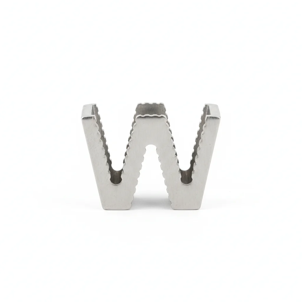
| W-Type Grounding Clamp | Rail Grounding Clamp | Frame Grounding Clamp | Copper Braid Grounding Strap (Reinforced) | Copper-Based Conductive Paste | |
|---|---|---|---|---|---|
| SPEC | For 10mm² ground wire | For C-channel rail | For 30-50mm frame | 16mm² Tin-plated | 100g/tube |
| MATERIAL | 316 Stainless Steel with Spiked Teeth | 316 Stainless Steel | 316 Stainless Steel with Teeth | T2 Copper Tin-plated | Copper-Based Conductive Paste |
| GRADE | UL 467+DNV | UL 467 | UL 467 | IEC 62305 Class I Lightning Protection | Contact resistance <5μΩ·cm² |
| FINISH | HDG >=55um per ISO 1461 | HDG >=55um per ISO 1461 | HDG >=55um per ISO 1461 | HDG >=55um per ISO 1461 | HDG >=55um per ISO 1461 |
| CORROSION | C3 (ISO 12944-2) | C3 (ISO 12944-2) | C3 (ISO 12944-2) | C3 (ISO 12944-2) | C3 (ISO 12944-2) |
| TEMP | -20°C to +80°C | -20°C to +80°C | -20°C to +80°C | -20°C to +80°C | -20°C to +80°C |
| WEIGHT | ~0.5 kg/piece | ~0.5 kg/piece | ~0.5 kg/piece | ~0.5 kg/piece | ~0.5 kg/piece |
| MOQ | 100 pcs | 100 pcs | 100 pcs | 100 pcs | 100 pcs |
| PACK | VCI paper + carton | VCI paper + carton | VCI paper + carton | VCI paper + carton | VCI paper + carton |
| STD | ISO 898-1, GB/T 3098.1 | ISO 898-1, GB/T 3098.1 | ISO 898-1, GB/T 3098.1 | ISO 898-1, GB/T 3098.1 | ISO 898-1, GB/T 3098.1 |
| USE | C5 environment module grounding | Coastal power station rail grounding | Coastal power station module grounding | Class I lightning protection level grounding connection | Apply to all grounding connection surfaces |
PROCEDURE
- Degrease the aluminum frame and rail contact zones with acetone, then abrade the anodized surface where the 316 spiked teeth will bite.
- Apply copper-based conductive paste (contact resistance <5μΩ·cm²) to the copper braid terminal and the frame contact patch.
- Position the 316 W-Type clamp with spiked teeth facing the frame, ensuring the 16mm² tin-plated copper braid is routed without sharp bends.
- Tighten the M6/M8 bolt progressively in a cross pattern to the torque specified for 316 stainless (per ISO 898-1), then verify with a calibrated wrench.
- Measure contact resistance from frame to braid with a micro-ohmmeter—must read below 0.01Ω per UL 467; re-torque if higher.
- Mark each clamp with a torque seal and log the installation date, torque value, and environmental conditions for the 25-year service record.
COMMON ERRORS
| ✕ WRONG | CONSEQUENCE | ✓ CORRECT |
|---|---|---|
| Bolt tightened below the specified torque for 316 stainless steel | Contact resistance stays above 0.01Ω, and under a 100kA lightning surge the high-impedance point arcs, pitting the clamp and frame. | Torque to the value given for M6/M8 316 fasteners (per ISO 898-1) and confirm with a micro-ohmmeter that resistance is below 0.01Ω. |
| Skipping conductive paste between the copper braid and aluminum frame | Moisture ingress creates a Cu-Al galvanic cell (potential difference ~2V), producing white Al₂O₃ corrosion that disconnects the ground within 1-2 years. | Coat both contact faces with copper-based conductive paste (contact resistance <5μΩ·cm²) before assembly. |
MAINTENANCE
Before each thunderstorm season, visually inspect all clamps for corrosion or loosening; annually disassemble a 10% sample to check for white Al₂O₃ powder on contact surfaces, re-torque any clamp below 80% of the specified value, and replace any with pitting deeper than 0.3mm or corrosion covering more than 5% of the surface.
Plan C · Extreme Environment / Regulatory Compliance
C5-M offshore / Class I lightning per ISO 12944-2 with DNV GL certification
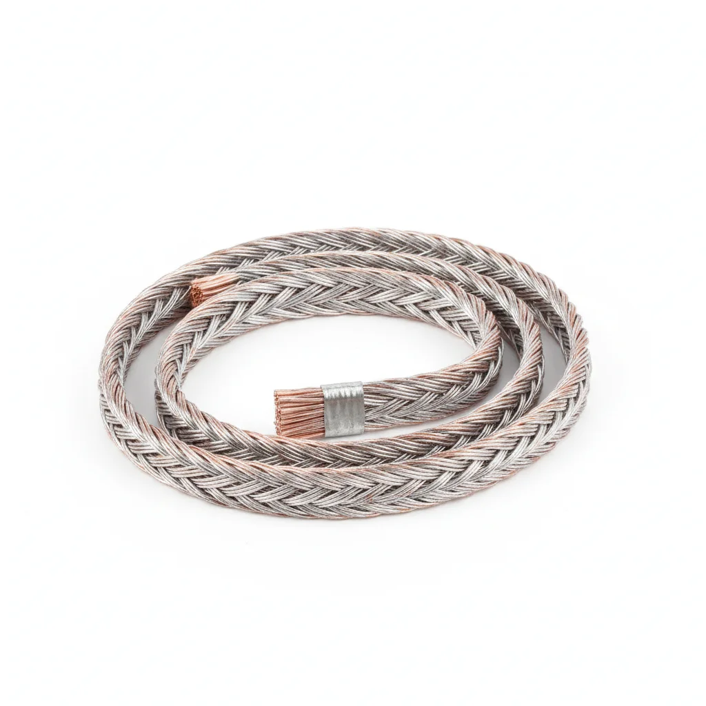
| W-Type Grounding Clamp | Multi-Grounding Clamp | Silver-Plated Copper Braid Grounding Strap | Silver-Based Conductive Paste | Grounding Terminal | |
|---|---|---|---|---|---|
| SPEC | For 16mm² ground wire | For C-channel + frame + ground wire | 16mm² Silver-plated | 50g/tube | M6-M10 |
| MATERIAL | 316L Stainless Steel Electropolished | 316L Stainless Steel | T2 Copper Silver-plated | Silver-Based Conductive Paste | 316L Stainless Steel |
| GRADE | UL 467+DNV GL | IP68 | IEC 62305 | Contact resistance <1μΩ·cm² | Electropolished |
| FINISH | HDG >=55um per ISO 1461 | HDG >=55um per ISO 1461 | HDG >=55um per ISO 1461 | HDG >=55um per ISO 1461 | HDG >=55um per ISO 1461 |
| CORROSION | C3 (ISO 12944-2) | C3 (ISO 12944-2) | C3 (ISO 12944-2) | C3 (ISO 12944-2) | C3 (ISO 12944-2) |
| TEMP | -20°C to +80°C | -20°C to +80°C | -20°C to +80°C | -20°C to +80°C | -20°C to +80°C |
| WEIGHT | ~0.5 kg/piece | ~0.5 kg/piece | ~0.5 kg/piece | ~0.5 kg/piece | ~0.5 kg/piece |
| MOQ | 100 pcs | 100 pcs | 100 pcs | 100 pcs | 100 pcs |
| PACK | VCI paper + carton | VCI paper + carton | VCI paper + carton | VCI paper + carton | VCI paper + carton |
| STD | ISO 898-1, GB/T 3098.1 | ISO 898-1, GB/T 3098.1 | ISO 898-1, GB/T 3098.1 | ISO 898-1, GB/T 3098.1 | ISO 898-1, GB/T 3098.1 |
| USE | Offshore platform module grounding | Offshore environment all-in-one grounding | Highest conductivity grounding | All grounding connections on offshore platform | Offshore grounding system wiring |
PROCEDURE
- Clean the 316L clamp teeth and frame contact area with MEK, then lightly sand the anodized layer where teeth will penetrate.
- Apply silver-based conductive paste (contact resistance <1μΩ·cm²) to the silver-plated braid terminal and the frame surface.
- Mount the multi-grounding clamp so its 316L teeth pierce the frame oxide layer, and connect the 16mm² silver-plated braid to the grounding busbar.
- Tighten the M6-M10 bolt with a hydraulic tensioner to the torque for 316L per ISO 898-1, then verify with a calibrated wrench and mark.
- Perform a dye-penetrant test on 10% of the installed clamps to confirm no micro-cracks from tightening.
- Measure contact resistance with a micro-ohmmeter—each point must be below 0.01Ω per UL 467—and record all data for DNV GL audit.
COMMON ERRORS
| ✕ WRONG | CONSEQUENCE | ✓ CORRECT |
|---|---|---|
| Using a 304 or 316 clamp in the offshore salt-spray zone | Chloride pitting initiates within months, increasing contact resistance and compromising the lightning path before the 25-year design life. | Specify 316L electropolished clamps with DNV GL certification, which resist pitting in C5-M environments. |
| Omitting the silver-based conductive paste on the silver-plated braid connection | Micro-movement and salt ingress create high resistance at the joint, leading to overheating and arcing under lightning current. | Apply silver-based paste (contact resistance <1μΩ·cm²) to every connection surface before tightening. |
MAINTENANCE
At each overhaul window (typically 3-5 years) and before the thunderstorm season, inspect all clamps for chloride pitting or loosening; annually test a 10% sample by disassembly to verify contact surfaces remain free of corrosion products, re-torque any clamp below 80% of specification, and replace any showing pitting depth >0.3mm or corrosion area >5%.
REFERENCED STANDARDS
Referenced Standards and Authoritative References
International standard for lightning protection grounding design of PV arrays, specifying grounding resistance requirements for Class I-IV lightning protection levels.
Grounding and Bonding EquipmentUL safety standard for grounding clamps and grounding connectors.
Electrical Installations – Earthing Arrangements and Protective ConductorsBasic standard for grounding system design and construction.
Code for Design of Lightning Protection of BuildingsMandatory standard for lightning protection design of domestic PV power stations in China.
Mechanical Properties of Corrosion-Resistant Stainless Steel FastenersBasis for material selection of 304/316/316L grounding clamps.
Lightning ProtectionSUPPLIER CAPABILITY
Quality, Delivery & Customization
Quality Control
- ✓MTC material certificates with every batch
- ✓Key parts sampled for hardness/salt spray/torque coefficient
- ✓100% inspection or AQL sampling before shipment
Delivery
- ✓Standard parts made to order: 7-15 days
- ✓Custom parts: 25-45 days
- ✓FOB/CIF/DDP supported
Customization
- ✓Drawing review and material matching
- ✓Non-standard sizes/heads/threads
- ✓Small-batch prototyping supported
Certification
- ✓Material certificates (MTC)
- ✓Spectrographic analysis reports
- ✓Salt spray test reports (on request)
MOQ: No MOQ for standard parts; custom parts assessed by process complexity
FAQ
Frequently Asked Questions
RELATED READING
Keep Reading & Next Step
BEYOND TECHNICAL SPECS
Finding the right factory, controlling quality, delivering on time — that's the real challenge. We cover fasteners, rubber, plastics, industrial textiles. One team, end to end.
SEE CAPABILITIES →