
Inverter Mounting Brackets and Fasteners Comparison
Selecting the right mounting bracket and fasteners for solar inverters is critical to prevent vibration-induced bolt loosening, heat dissipation failure, and fire risks. Compare wall-mount (20-60kW) and floor-mount (60-500kW) configurations, including materials, coatings, and anti-loosen hardware
RISK AUDIT // ENGINEERING DIAGNOSIS
Procurement Pitfall Guide
"Field failures in inverter mounting often trace back to overlooked mechanical details—here are the pitfalls we see most."
QC-AUDIT // REV.5
SCALE 1:1 · 03 ITEMS
RISK-01
Inverter Weight Underestimation Leading to Bracket Overload
Corrective Measures
RISK-02
Wind Vibration and Heat Dissipation Causing Bolt Loosening
Corrective Measures
RISK-03
Fan Vibration Transmitted to DC Terminals Causing Loosening, Arcing, and Fire
Corrective Measures
FIELD-SPECIFIC INSIGHT
Critical Fastener Checks for Inverter Mounting
Inverter mounting failures often stem from underestimated vibration and corrosion. The table below highlights key inspection points for procurement and installation
WHAT TO CHECK
- 1Wall-mount brackets for 20-60kW inverters require load capacity ≥80kg; verify bracket material Q235B hot-dip galvanized ≥65μm per ISO 1461
- 2Floor-mount brackets for 60-500kW inverters need load capacity ≥1500kg; use Q345B hot-dip galvanized ≥85μm and M16 high-strength bolts grade 10.9
- 3Vibration from inverter fans (5-20Hz) can loosen ordinary bolts; use nylon lock nuts or wedge lock washers to maintain preload
- 4In coastal C5 environments, upgrade to 316L stainless steel fasteners and FFKM vibration dampers to prevent corrosion and maintain damping
- 5DC terminal bolt loosening increases contact resistance, causing local heating and fire risk; specify anti-loosen hardware and periodic torque checks
| Check | Why it matters | What to specify |
|---|---|---|
| Bracket load capacity vs inverter weight | Underestimated weight leads to weld fatigue and collapse | Safety factor ≥2.5; verify load capacity in datasheet |
| Bolt material and coating | Corrosion reduces bolt strength; galvanic corrosion with bracket | Hot-dip galvanized ≥65μm for C3; 316L for C5 |
| Anti-loosen feature | Vibration decays preload 30-50% after 10⁴ cycles (order-of-magnitude estimate) | Nylon lock nut or wedge lock washer; specify prevailing torque type |
| Vibration damper hardness | Too soft damper causes excessive movement; too hard transmits vibration | Shore hardness 50-55 for wall-mount; 60-65 for floor-mount |
| DC terminal bolt torque | Loose terminal causes arcing and fire | Torque per manufacturer spec; use lock washers; periodic re-torque |
All fastener specifications must be verified against inverter manufacturer's installation manual. Torque values and inspection intervals are project-specific
Evidence level: source-page-only
INDUSTRY TECH REFERENCE
From an Under-Torqued Base Bolt to a DC Arc
A torque problem at the base bolt travels along the vibration path to the DC side and ends in an arc.
- 1Inverter base expansion bolts (M12) go to 50-60 N·m (stainless steel product rating) — a torque shortfall shows up first as wind-vibration shifting
- 2Shifting strains the DC cables, loosening the MC4 connectors they feed
- 3An unlatched MC4 → higher contact resistance → heating → oxidation → more heat → meltdown
- 4A DC arc has no zero crossing and cannot self-extinguish → fire
- 5Fix it upfront: 304 SS with nylon-insert lock nuts; latch MC4s until they click, then tug-test; scan by IR thermography yearly and treat any hot spot above 10 °C as abnormal (recommended)
The M12 50-60 N·m value is the stainless expansion-bolt product rating (verified in KB §2.4, not an estimate); >10 °C is recommended; the MC4-to-arc mechanism chain follows KB §2.6.
INDUSTRY TECH REFERENCE
Inverter Base Expansion Bolts: Don't Use Steel Torque Values
For the same M12, a stainless expansion bolt and an 8.8 steel one take very different installation torque — match them against this table when ordering and installing.
| Item / size | Torque or spec | Notes |
|---|---|---|
| Inverter base expansion bolt, stainless (M12) | 50-60 N·m | Stainless product rating — follow the maker's spec, not steel values |
| 8.8-grade steel expansion bolt (M12, for reference) | 96-110 N·m | Steel rating, clearly higher — don't mix the two materials |
| Base mounting bolts (anti-vibration setup) | M8-M12, 304 SS + nylon-insert lock nuts | Common base sizes; wind-vibration loosening is the main failure |
Both 50-60 and 96-110 N·m are verified readings from KB §2.4 (stainless expansion-bolt product rating vs 8.8 steel), not estimates; M8-M12/304 per KB §5.
INDUSTRY TECH REFERENCE
Inverter Base Bolts: Locking Choices and Torque Patrol
Wind vibration is the main enemy of base bolts — pick the right locking hardware, then patrol yearly; skip neither.
- Wind-vibration loosening is the main failure of base bolts — fit nylon-insert lock nuts plus spring washers, not plain flat washers
- Torque patrol: sample 10% of the bolts every year; re-tighten the whole batch when decay exceeds 20%
- Material follows the site: 8.8-grade HDG ≥85 μm inland (or per GB/T 13912 tiers); Dacromet or 304 near the coast
- IR scan once a year: a hot spot above 10 °C at the inverter base or terminals is abnormal (recommended)
The 10% sampling and >20% full-batch re-tightening follow KB §2.2 (anchor/U-bolt basis, extended to inverter bases); ≥85 μm per §2.2; >10 °C is a recommended value (§2.4); Dacromet follows the §2.2/§2.3 options. No magnitude estimates.
PLAN COMPARISON
Three-Plan Core Parameter Comparison
Compare row by row. Click column headers to jump to plan details.
| A · Plan A · Wall-Mounted Standard Configuration (20-60kW) | B · Plan B · Floor-Mounted Reinforced Configuration (60-500kW) | C · Plan C · Extreme Environment/Offshore Configuration | |
|---|---|---|---|
| 1. INVERTER WALL-MOUNT BRACKET | |||
| SPEC | For 20-60kW inverter (load capacity ≥80kg) | For 60-500kW, load capacity ≥1500kg | Custom, load capacity ≥2000kg |
| MATERIAL | Q235B Hot-dip Galvanized ≥65μm | Q345B Hot-dip Galvanized ≥85μm | 316L Stainless Steel |
| GRADE | Hot-dip Galvanized | Hot-dip Galvanized + Anti-corrosion Paint | Electropolished |
| FINISH | HDG >=55um per ISO 1461 | HDG >=55um per ISO 1461 | HDG >=55um per ISO 1461 |
| 2. M12 CHEMICAL ANCHOR | |||
| SPEC | M12×160mm | M16×200mm Embedded Type | M16×200mm |
| MATERIAL | Carbon Steel Galvanized + Epoxy Resin Cartridge | 42CrMoA Hot-Dip Galvanized | 316L Stainless Steel + Epoxy |
| GRADE | Tensile Strength ≥18kN | Grade 10.9 | A4-80 |
| FINISH | HDG >=55um per ISO 1461 | HDG >=55um per ISO 1461 | HDG >=55um per ISO 1461 |
| 3. MOUNTING BOLT | |||
| SPEC | M10×30mm | M16×40mm | M16×40mm |
| MATERIAL | 304 Stainless Steel A2-70 | 42CrMoA | 316L Stainless Steel |
| GRADE | Plain | Grade 10.9 | A4-80 |
| FINISH | HDG >=55um per ISO 1461 | HDG >=55um per ISO 1461 | HDG >=55um per ISO 1461 |
| 4. NYLON INSERT LOCK NUT | |||
| SPEC | M10 | NL16 | NL16sp |
| MATERIAL | Carbon Steel Galvanized + Nylon Insert | Carbon Steel Hardened + Dacromet | 316L Stainless Steel |
| GRADE | Hot-dip Galvanized | Dacromet | Electropolished |
| FINISH | HDG >=55um per ISO 1461 | HDG >=55um per ISO 1461 | HDG >=55um per ISO 1461 |
| 5. NATURAL RUBBER VIBRATION DAMPER | |||
| SPEC | 50×50×10mm | 80×80×12mm | 80×80×12mm |
| MATERIAL | Natural Rubber NR | Natural Rubber NR | FFKM Perfluoroelastomer |
| GRADE | Shore Hardness 50-55 | Shore Hardness 60-65 | Temperature Resistance -40~250°C |
| FINISH | HDG >=55um per ISO 1461 | HDG >=55um per ISO 1461 | HDG >=55um per ISO 1461 |
SELECTION GUIDE
Still unsure which mounting plan fits your site?
| Operating condition | Recommended option | Key basis |
|---|---|---|
| String inverter <60kW, wall mounting on concrete/brick wall | Plan A Wall-Mounted: Q235B hot-dip galvanized ≥65μm bracket (load ≥80kg) + M12 chemical anchor (tensile ≥18kN) + 304 A2-70 bolts + nylon lock nut | GB 50017-2017, GB/T 5783/ISO 4017, GB/T 889.1/ISO 7040 |
| Central/string inverter >60kW or floor-mounted | Plan B Floor-Mounted: Q345B hot-dip galvanized ≥85μm bracket (load ≥1500kg) + M16 Grade 10.9 high-strength bolts + wedge lock washer | GB 50017-2017, SS-EN 14399, ISO 12944-2 C4 |
| Within 3km of coast / offshore platform | Plan C Full 316L: 316L floor bracket (load ≥2000kg) + A4-80 fasteners + 316L wedge lock washer | ISO 12944-2 C5-M |
Plan A · Wall-Mounted Standard Configuration (20-60kW)
C3 (ISO 12944-2), HDG ≥65μm
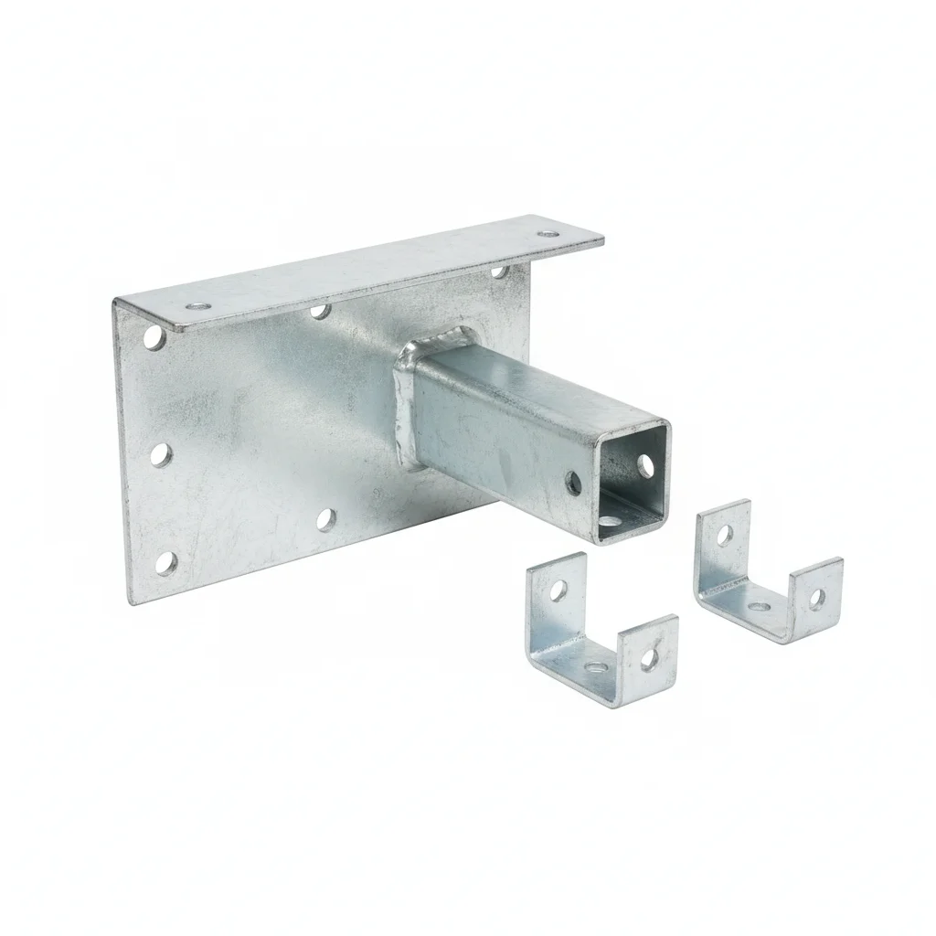
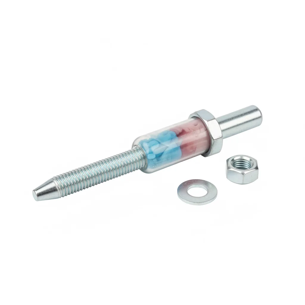
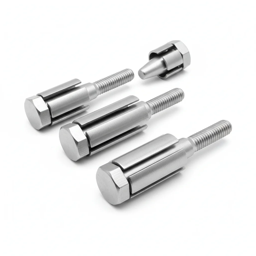
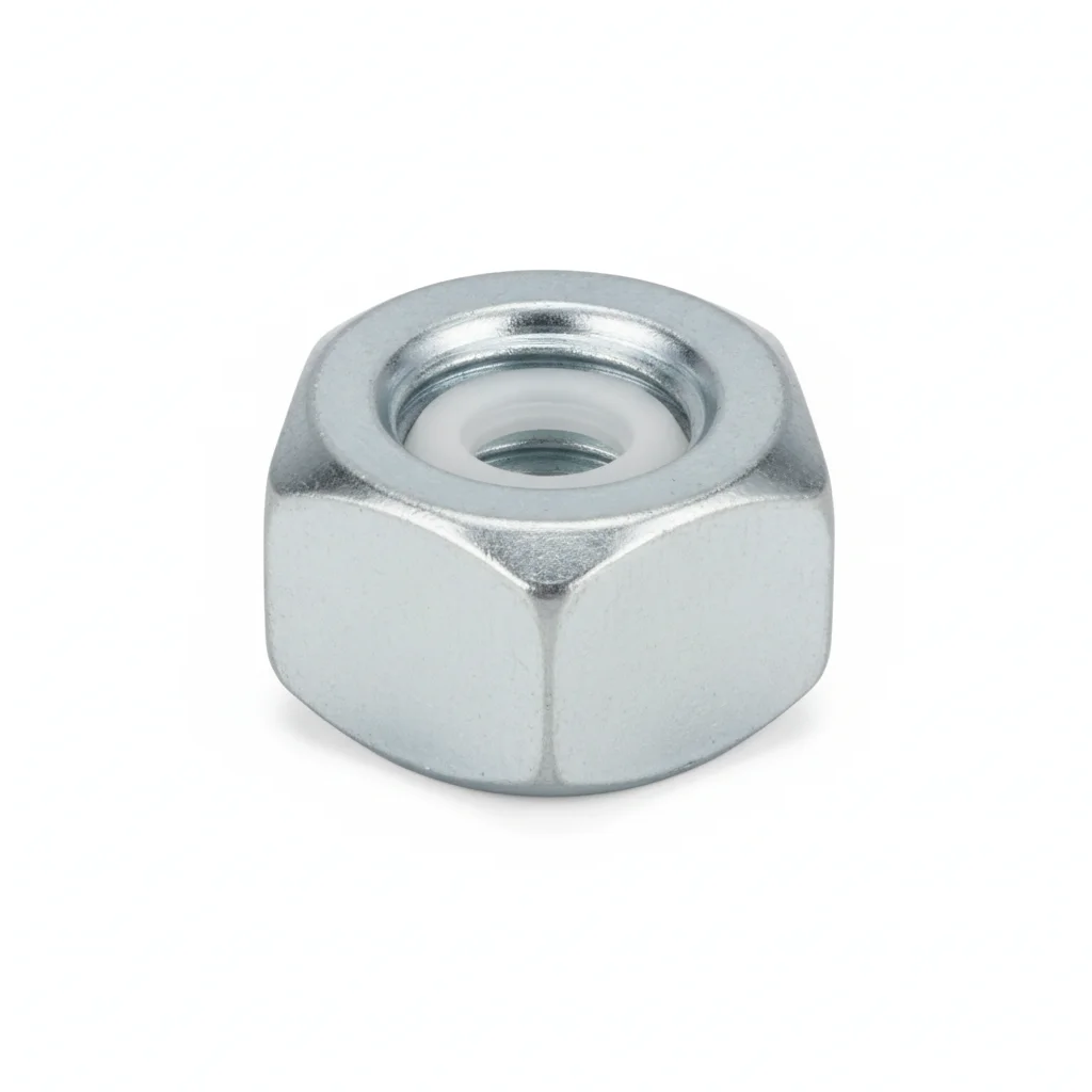
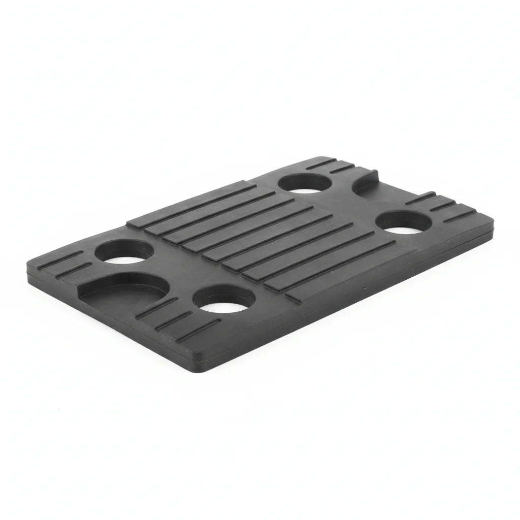
| Inverter Wall-Mount Bracket | M12 Chemical Anchor | Mounting Bolt | Nylon Insert Lock Nut | Natural Rubber Vibration Damper | |
|---|---|---|---|---|---|
| SPEC | For 20-60kW inverter (load capacity ≥80kg) | M12×160mm | M10×30mm | M10 | 50×50×10mm |
| MATERIAL | Q235B Hot-dip Galvanized ≥65μm | Carbon Steel Galvanized + Epoxy Resin Cartridge | 304 Stainless Steel A2-70 | Carbon Steel Galvanized + Nylon Insert | Natural Rubber NR |
| GRADE | Hot-dip Galvanized | Tensile Strength ≥18kN | Plain | Hot-dip Galvanized | Shore Hardness 50-55 |
| FINISH | HDG >=55um per ISO 1461 | HDG >=55um per ISO 1461 | HDG >=55um per ISO 1461 | HDG >=55um per ISO 1461 | HDG >=55um per ISO 1461 |
| CORROSION | C3 (ISO 12944-2) | C3 (ISO 12944-2) | C3 (ISO 12944-2) | C3 (ISO 12944-2) | C3 (ISO 12944-2) |
| TEMP | -20°C to +80°C | -20°C to +80°C | -20°C to +80°C | -20°C to +80°C | -20°C to +80°C |
| WEIGHT | ~0.5 kg/piece | ~0.5 kg/piece | ~0.5 kg/piece | ~0.5 kg/piece | ~0.5 kg/piece |
| MOQ | 100 pcs | 100 pcs | 100 pcs | 100 pcs | 100 pcs |
| PACK | VCI paper + carton | VCI paper + carton | VCI paper + carton | VCI paper + carton | VCI paper + carton |
| STD | ISO 898-1, GB/T 3098.1 | ISO 898-1, GB/T 3098.1 | ISO 898-1, GB/T 3098.1 | ISO 898-1, GB/T 3098.1 | ISO 898-1, GB/T 3098.1 |
| USE | Inverter wall mounting | Fixing bracket to concrete wall | Connecting inverter to bracket | Used with mounting bolt | Vibration damping between bracket and inverter |
PROCEDURE
- Drill holes for M12 chemical anchors in the concrete/brick wall, then clean dust with a brush and blow-out pump.
- Inject the epoxy resin cartridge into the hole, insert the M12×160mm chemical anchor, and allow full cure per the resin data sheet.
- Position the Q235B hot-dip galvanized bracket (load capacity ≥80kg) and secure with the chemical anchors; ensure level using a spirit level.
- Place the natural rubber vibration damper (Shore 50-55) between bracket and inverter, then mount the inverter with M10×30mm 304 stainless steel bolts and nylon insert lock nuts.
- Tighten the M10 bolts to the torque specified in the inverter manual, then verify the inverter is firmly seated against the damper.
COMMON ERRORS
| ✕ WRONG | CONSEQUENCE | ✓ CORRECT |
|---|---|---|
| Using carbon steel bolts instead of 304 stainless steel for the inverter-to-bracket connection. | Carbon steel bolts corrode and seize in outdoor C3 environments, leading to difficult maintenance and potential loss of preload. | Use 304 stainless steel A2-70 bolts (M10×30mm) with nylon insert lock nuts (GB/T 889.1) to resist corrosion and vibration loosening. |
| Overtightening the M10 bolts beyond the manufacturer's recommended torque. | Excessive torque can strip threads or crush the rubber damper, reducing vibration isolation and causing premature loosening. | Follow the inverter manual's torque specification for M10 fasteners; use a calibrated torque wrench and do not exceed the stated value. |
| Neglecting to use the vibration damper between bracket and inverter. | Fan vibration (5-20Hz) is transmitted directly to the bracket, accelerating preload decay of bolts and increasing noise. | Install the natural rubber vibration damper (50×50×10mm, Shore 50-55) to isolate vibration and maintain bolt preload. |
MAINTENANCE
Re-torque the M10 mounting bolts and M12 chemical anchors at each seasonal inspection and after any high-wind event; verify the nylon insert lock nuts still provide prevailing torque. Check the rubber damper for cracks or permanent set. Inspect the galvanized bracket for coating damage per ISO 1461 and touch up with zinc-rich paint if the galvanizing is scratched.
Plan B · Floor-Mounted Reinforced Configuration (60-500kW)
C4 Harsh per ISO 12944-2
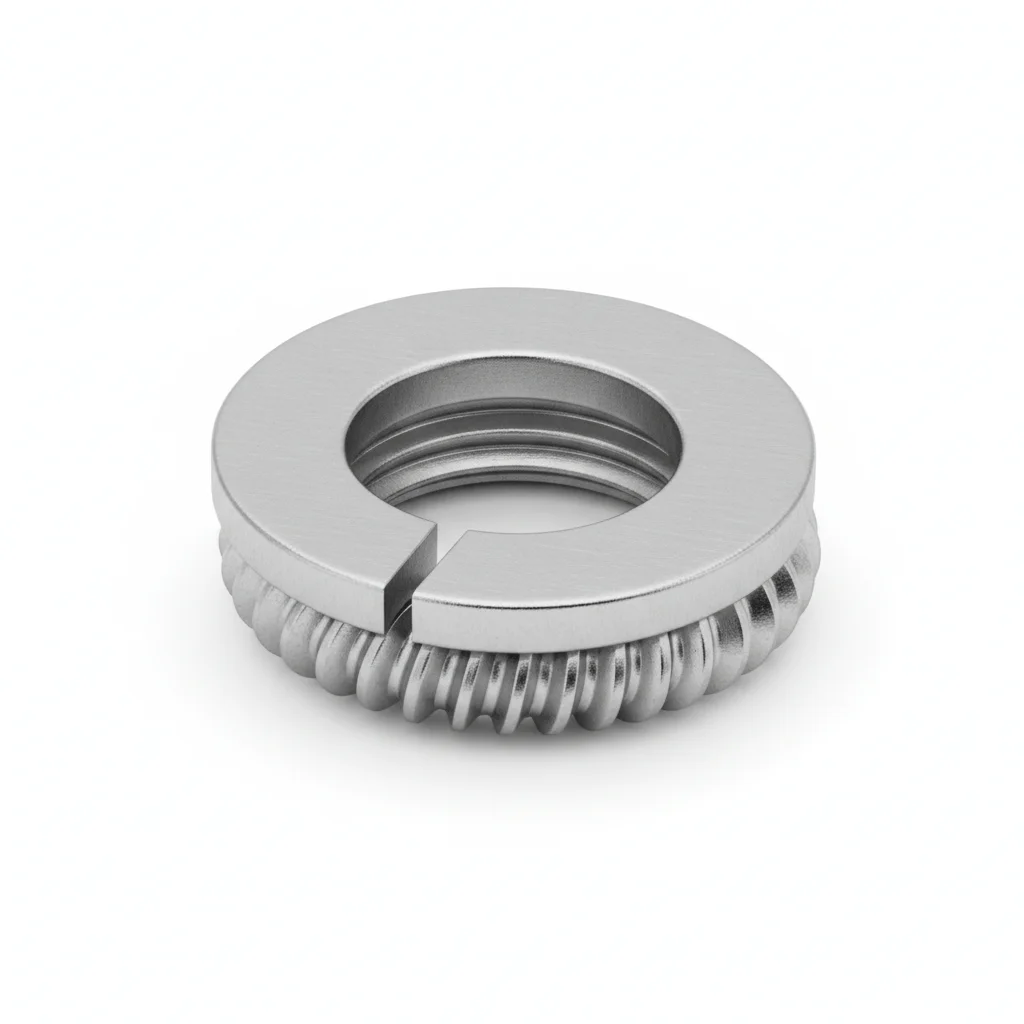
| Inverter Floor-Mount Bracket | M16 Anchor Bolt | M16 High-Strength Bolt | Wedge Lock Washer | Reinforced Vibration Damper | |
|---|---|---|---|---|---|
| SPEC | For 60-500kW, load capacity ≥1500kg | M16×200mm Embedded Type | M16×40mm | NL16 | 80×80×12mm |
| MATERIAL | Q345B Hot-dip Galvanized ≥85μm | 42CrMoA Hot-Dip Galvanized | 42CrMoA | Carbon Steel Hardened + Dacromet | Natural Rubber NR |
| GRADE | Hot-dip Galvanized + Anti-corrosion Paint | Grade 10.9 | Grade 10.9 | Dacromet | Shore Hardness 60-65 |
| FINISH | HDG >=55um per ISO 1461 | HDG >=55um per ISO 1461 | HDG >=55um per ISO 1461 | HDG >=55um per ISO 1461 | HDG >=55um per ISO 1461 |
| CORROSION | C3 (ISO 12944-2) | C3 (ISO 12944-2) | C3 (ISO 12944-2) | C3 (ISO 12944-2) | C3 (ISO 12944-2) |
| TEMP | -20°C to +80°C | -20°C to +80°C | -20°C to +80°C | -20°C to +80°C | -20°C to +80°C |
| WEIGHT | ~0.5 kg/piece | ~0.5 kg/piece | ~0.5 kg/piece | ~0.5 kg/piece | ~0.5 kg/piece |
| MOQ | 100 pcs | 100 pcs | 100 pcs | 100 pcs | 100 pcs |
| PACK | VCI paper + carton | VCI paper + carton | VCI paper + carton | VCI paper + carton | VCI paper + carton |
| STD | ISO 898-1, GB/T 3098.1 | ISO 898-1, GB/T 3098.1 | ISO 898-1, GB/T 3098.1 | ISO 898-1, GB/T 3098.1 | ISO 898-1, GB/T 3098.1 |
| USE | Large inverter floor mounting | Fixing bracket to concrete foundation | Connecting inverter to bracket | Replaces ordinary spring washer | Large inverter vibration damping |
PROCEDURE
- Position the floor-mount bracket on the concrete foundation, aligning the M16 embedded anchor bolts with the bracket holes.
- Level the bracket using shims; ensure verticality within the tolerance specified in GB 50017.
- Place the M16 high-strength bolts (Grade 10.9) through the inverter mounting feet and bracket, adding wedge lock washers under the nut.
- Tighten the bolts in a cross-pattern sequence to the torque specified by the inverter manufacturer; do not exceed the yield strength.
- After initial tightening, mark the bolt heads and nuts with a paint line to enable visual detection of loosening.
- Install the reinforced vibration damper between the inverter and bracket, ensuring full contact and no gaps.
COMMON ERRORS
| ✕ WRONG | CONSEQUENCE | ✓ CORRECT |
|---|---|---|
| Using ordinary flat washers instead of wedge lock washers | Vibration from the inverter fan (5-20Hz) gradually loosens the bolts, leading to reduced heat dissipation and potential structural failure. | Use the specified NL16 wedge lock washers, which maintain preload under vibration. |
| Tightening M16 high-strength bolts without a calibrated torque wrench | Inconsistent preload may cause bolt overloading or loosening, risking bracket fatigue. | Use a calibrated torque wrench and follow the torque values given in the inverter installation manual. |
MAINTENANCE
Re-torque the M16 bolts at the 3-month and 12-month marks after installation, then annually. Check for torque decay; if it exceeds 15%, replace the bolt and wedge lock washer. Inspect for corrosion on the galvanized coating and touch up any damaged areas.
Plan C · Extreme Environment/Offshore Configuration
C5-M Extreme per ISO 12944-2
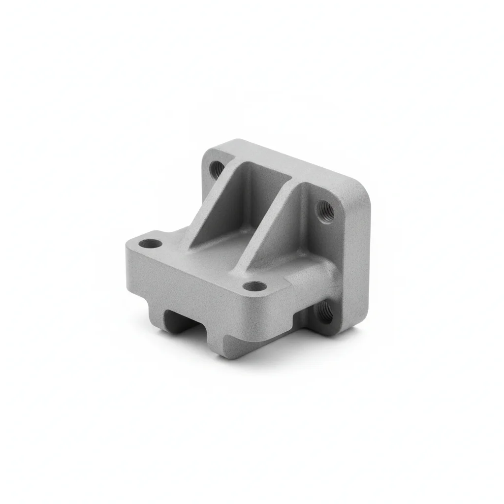
| Floor-Mount Bracket | Chemical Anchor | High-Strength Bolt | Wedge Lock Washer | Vibration Damper | |
|---|---|---|---|---|---|
| SPEC | Custom, load capacity ≥2000kg | M16×200mm | M16×40mm | NL16sp | 80×80×12mm |
| MATERIAL | 316L Stainless Steel | 316L Stainless Steel + Epoxy | 316L Stainless Steel | 316L Stainless Steel | FFKM Perfluoroelastomer |
| GRADE | Electropolished | A4-80 | A4-80 | Electropolished | Temperature Resistance -40~250°C |
| FINISH | HDG >=55um per ISO 1461 | HDG >=55um per ISO 1461 | HDG >=55um per ISO 1461 | HDG >=55um per ISO 1461 | HDG >=55um per ISO 1461 |
| CORROSION | C3 (ISO 12944-2) | C3 (ISO 12944-2) | C3 (ISO 12944-2) | C3 (ISO 12944-2) | C3 (ISO 12944-2) |
| TEMP | -20°C to +80°C | -20°C to +80°C | -20°C to +80°C | -20°C to +80°C | -20°C to +80°C |
| WEIGHT | ~0.5 kg/piece | ~0.5 kg/piece | ~0.5 kg/piece | ~0.5 kg/piece | ~0.5 kg/piece |
| MOQ | 100 pcs | 100 pcs | 100 pcs | 100 pcs | 100 pcs |
| PACK | VCI paper + carton | VCI paper + carton | VCI paper + carton | VCI paper + carton | VCI paper + carton |
| STD | ISO 898-1, GB/T 3098.1 | ISO 898-1, GB/T 3098.1 | ISO 898-1, GB/T 3098.1 | ISO 898-1, GB/T 3098.1 | ISO 898-1, GB/T 3098.1 |
| USE | C5-M environment inverter installation | Coastal/offshore foundation fixing | Connecting inverter to bracket | Highest anti-loosening level for offshore environment | Extreme environment on offshore platforms |
PROCEDURE
- Clean the contact surfaces with a solvent suitable for stainless steel to remove any contamination.
- Position the floor-mount bracket on the foundation, aligning the 316L chemical anchor holes.
- Set the 316L high-strength bolts (A4-80) with 316L wedge lock washers; ensure the fasteners are free from any carbon steel contact to avoid galvanic corrosion.
- Tighten the bolts gradually in a star pattern to the torque specified for A4-80 fasteners.
- Apply a marine-grade anti-seize compound on the threads to prevent galling in the coastal environment.
- Install the FFKM vibration damper, which withstands the temperature range of -40 to 250°C.
COMMON ERRORS
| ✕ WRONG | CONSEQUENCE | ✓ CORRECT |
|---|---|---|
| Mixing carbon steel bolts with 316L bracket in a coastal environment | Rapid galvanic corrosion of the carbon steel, leading to premature failure within months. | Use only 316L stainless steel fasteners (A4-80) and 316L wedge lock washers. |
| Overtightening A4-80 bolts, causing thread galling | Galling seizes the threads, making future disassembly impossible and damaging the bolt. | Apply anti-seize lubricant and tighten to the manufacturer's specified torque. |
MAINTENANCE
Inspect fasteners seasonally for any signs of corrosion or loosening, especially after storms. Re-torque if loosening is detected. Replace any fastener showing pitting or corrosion. Verify the integrity of the FFKM damper, which is rated for -40 to 250°C.
REFERENCED STANDARDS
Referenced Standards and Authoritative References
Design calculation basis for bracket structural load capacity and stability.
Hexagon head bolts — Product grades A and BStandard for dimensions and mechanical properties of general purpose hexagon head bolts.
Prevailing torque type hexagon nuts (with non-metallic insert)Performance requirements for nylon lock nuts.
High-strength structural bolting assemblies for preloadingEuropean standard for wedge lock washers used with high-strength bolts for anti-loosening.
Protection against lightning — Part 3: Physical damage to structures and life hazardDesign reference standard for lightning protection grounding of inverter brackets.
Safety of power converters for use in photovoltaic power systemsSUPPLIER CAPABILITY
Quality, Delivery & Customization
Quality Control
- ✓MTC material certificates with every batch
- ✓Key parts sampled for hardness/salt spray/torque coefficient
- ✓100% inspection or AQL sampling before shipment
Delivery
- ✓Standard parts made to order: 7-15 days
- ✓Custom parts: 25-45 days
- ✓FOB/CIF/DDP supported
Customization
- ✓Drawing review and material matching
- ✓Non-standard sizes/heads/threads
- ✓Small-batch prototyping supported
Certification
- ✓Material certificates (MTC)
- ✓Spectrographic analysis reports
- ✓Salt spray test reports (on request)
MOQ: No MOQ for standard parts; custom parts assessed by process complexity
FAQ
Frequently Asked Questions
RELATED READING
Keep Reading & Next Step
BEYOND TECHNICAL SPECS
Finding the right factory, controlling quality, delivering on time — that's the real challenge. We cover fasteners, rubber, plastics, industrial textiles. One team, end to end.
SEE CAPABILITIES →