
Combiner Box Hardware: Compare Materials, Coatings, and Sealing for PV Plants
Combiner box hardware failures—rusted locks, aged seals, oxidized busbars—can force full box replacement. This page compares Plan A (304 SS, EPDM, C3), Plan B (316 SS, reinforced EPDM, C4), and Plan C (316L, FFKM, C5-M) to help you specify the right corrosion protection, sealing, and grounding components for your project environment
RISK AUDIT // ENGINEERING DIAGNOSIS
Procurement Pitfall Guide
"Field failures in combiner box hardware—seized locks, cracked seals, and oxidized busbars—are common pain points that can shut down entire PV strings."
QC-AUDIT // REV.5
SCALE 1:1 · 03 ITEMS
RISK-01
Door Locks and Hinges Seize, Preventing Maintenance Access
Corrective Measures
RISK-02
Aged Sealing Strip Leaks Water, Causing Electrical Faults
Corrective Measures
RISK-03
Oxidized Grounding Copper Busbar Causes Excessive Ground Resistance
Corrective Measures
FIELD-SPECIFIC INSIGHT
Key Differences Between Standard and Enhanced Combiner Box Hardware
While all plans use stainless steel screws and EPDM sealing strips, the material grade, lock type, and busbar plating differ . The wrong choice can lead to seized locks, water ingress, or high ground resistance within 3 years
WHAT TO CHECK
- 1304 SS screws (A2-70) are adequate for C3 inland; 316 SS (A4-70) or 316L (A4-80) required for coastal C4-C5 to avoid pitting corrosion
- 2Standard EPDM sealing strip (15x20mm hollow) works for C3; reinforced three-chamber EPDM (20x25mm) with 2000h salt spray resistance is needed for C4+ to prevent UV cracking and water ingress
- 3Triangular lock (zinc alloy + 304 body) is for C3; handle lock (316 SS) is easier to operate with gloves and more durable for large boxes in harsh environments
- 4Grounding busbar: tin-plated T2 copper (coating ≥8μm) for C3; tin+nickel underlayer or silver plating for C4-C5 to prevent oxidation and maintain contact resistance <0. 1Ω
| Check | Why it matters | What to specify |
|---|---|---|
| Screw material and grade | Corrosion resistance determines fastener life; seized screws prevent maintenance access | 304 A2-70 for C3, 316 A4-70 for C4, 316L A4-80 for C5-M per ISO 3506-1 |
| Sealing strip material and profile | Aged seals cause water ingress, leading to creepage and string shutdown | EPDM with temperature range -40~120°C; for coastal, specify reinforced three-chamber profile and salt spray resistance ≥2000h per ASTM D395 |
| Lock type and material | Rusted locks seize; handle lock allows gloved operation and withstands higher torque | Zinc alloy + 304 SS for C3; 316 SS handle lock for C4+; IP66 rating for export |
| Grounding busbar plating and thickness | Oxidation increases ground resistance, causing system ground fault and safety hazard | Tin plating ≥8μm for C3; tin+nickel underlayer or silver plating for C4-C5; busbar size per string current |
All specifications must be verified against project environment classification per ISO 12944-2. For export projects, IEC 61439 type test certification may require specific lock and busbar approvals
Evidence level: source-page-only
INDUSTRY TECH REFERENCE
Combiner Box Fastener and Grounding Specs at a Glance
Pin these down before ordering: the usual specs for combiner box mounting, internal fastening, and grounding hardware.
M8-M12, M6-M8 and the M12 50-60 N·m value are KB-sourced specs; ≤4 Ω is traced to GB 50169; >10 Ω is the joint-inspection threshold. No magnitude estimates.
INDUSTRY TECH REFERENCE
Grounding Acceptance: Getting It Right at the Combiner Box Hub
The combiner box is the aggregation point for string grounding — check the array target and the joint-by-joint target separately, never as one number.
| Check point | Key figure | Acceptance practice |
|---|---|---|
| Array ground resistance | ≤4 Ω (GB 50169) | Measure across the array at completion and before each lightning season |
| Joint contact resistance | Investigate above 10 Ω | Test point by point; redo any high-resistance joint |
| Serrated grounding washer | M6-M8, stainless steel + copper piercing points | Verify the washer has bitten through the anodized layer |
≤4 Ω is traced to GB 50169 (KB §2.5); >10 Ω and M6-M8 come from the KB; the before-lightning-season cadence follows KB §2.5. No magnitude estimates.
INDUSTRY TECH REFERENCE
A Combiner Box Burns Out Starting from One Loose Bolt
The causal chain from a loose mounting bolt to a burned-out box — short, and invisible from outside.
- 1The box is fixed to its post with M8-M12 bolts — when they loosen, the box tilts first
- 2Tilting strains the internal busbar joints; loose busbar connections mean higher contact resistance and continuous heating
- 3Heat builds up → overheating → burnout → full box replacement, far costlier than a few bolts
- 4Fix it upfront: 304 SS with nylon-insert lock nuts; scan by IR thermography yearly and treat any hot spot above 10 °C as abnormal (recommended) — don't wait for the burn
M8-M12 and the 304 SS + nylon-insert lock nut are KB-sourced; the >10 °C hot-spot threshold is a recommended value (noted in KB §2.4). No magnitude estimates.
INDUSTRY TECH REFERENCE
Annual Combiner Box Checks: IR Scan and Ground Test
The sneakiest failures stay invisible until lightning season — run these two gates every year.
- IR scan: treat any hot spot above 10 °C as abnormal (recommended); focus on busbar joints and terminals
- Before each lightning season, test array grounding and check that serrated washers have bitten through the anodized layer
- Investigate any joint above 10 Ω — don't wait for the whole-array target to fail
- Mounting bolts and door hardware in 304; if the box tilts, check mounting-bolt torque first
>10 °C is a recommended value (KB §2.4); the ≤4 Ω />10 Ω thresholds and serrated-washer bite check follow KB §2.5; the 304 choice follows the KB §2.4 options (304 SS + nylon lock nuts for combiner/inverter/transformer-box bolts). No magnitude estimates.
PLAN COMPARISON
Three-Plan Core Parameter Comparison
Compare row by row. Click column headers to jump to plan details.
| A · Plan A · Standard Outdoor Configuration | B · Plan B · High Protection Enhanced Configuration | C · Plan C · Extreme Environment/Export Configuration | |
|---|---|---|---|
| 1. COMBINER BOX MOUNTING SCREW SET | |||
| SPEC | M4/M5/M6 × Cross Recessed Pan Head | M4/M5/M6 | M4-M6 |
| MATERIAL | 304 Stainless Steel A2-70 | 316 Stainless Steel A4-70 | 316L Stainless Steel A4-80 |
| GRADE | Plain | Plain | Electropolished |
| FINISH | HDG >=55um per ISO 1461 | HDG >=55um per ISO 1461 | HDG >=55um per ISO 1461 |
| 2. COMBINER BOX TRIANGULAR LOCK | |||
| SPEC | Universal Triangular Lock Core | With Rotating Handle | Certified Grade Dual Point Locking |
| MATERIAL | Zinc Alloy Lock Core + 304 Stainless Steel Lock Body | 316 Stainless Steel | 316L Stainless Steel |
| GRADE | Chrome Plated | Plain | IP66 |
| FINISH | HDG >=55um per ISO 1461 | HDG >=55um per ISO 1461 | HDG >=55um per ISO 1461 |
| 3. COMBINER BOX STAINLESS STEEL HINGE | |||
| SPEC | 50×50mm × 2.0mm Thick | 60×60mm × 2.5mm | 60×60mm Removable Pin |
| MATERIAL | 304 Stainless Steel | 316 Stainless Steel | 316L Stainless Steel |
| GRADE | Plain | Plain | Electropolished |
| FINISH | HDG >=55um per ISO 1461 | HDG >=55um per ISO 1461 | HDG >=55um per ISO 1461 |
| 4. SEALING STRIP | |||
| SPEC | 15×20mm Hollow Structure | 20×25mm Three-Chamber Hollow | 15×20mm |
| MATERIAL | EPDM Rubber | EPDM Rubber | EPDM Rubber |
| GRADE | Black, Temperature Range -40~120°C | Black, Salt Spray Resistance 2000h | Temperature Range -40~250°C, Salt Spray Resistance 5000h |
| FINISH | HDG >=55um per ISO 1461 | HDG >=55um per ISO 1461 | HDG >=55um per ISO 1461 |
| 5. GROUNDING COPPER BUSBAR | |||
| SPEC | 5×20×150mm | 10×30×200mm | 10×30mm + Silver-based Conductive Paste |
| MATERIAL | T2 Copper, Tin Plated (Coating ≥8μm) | T2 Copper, Tin + Nickel Underlayer Plated | T2 Copper, Silver Plated |
| GRADE | Tin Plated | Tin Plated | Silver Plated |
| FINISH | HDG >=55um per ISO 1461 | HDG >=55um per ISO 1461 | HDG >=55um per ISO 1461 |
Plan A · Standard Outdoor Configuration
C3 Standard per ISO 12944-2
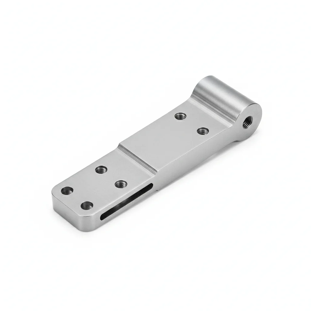
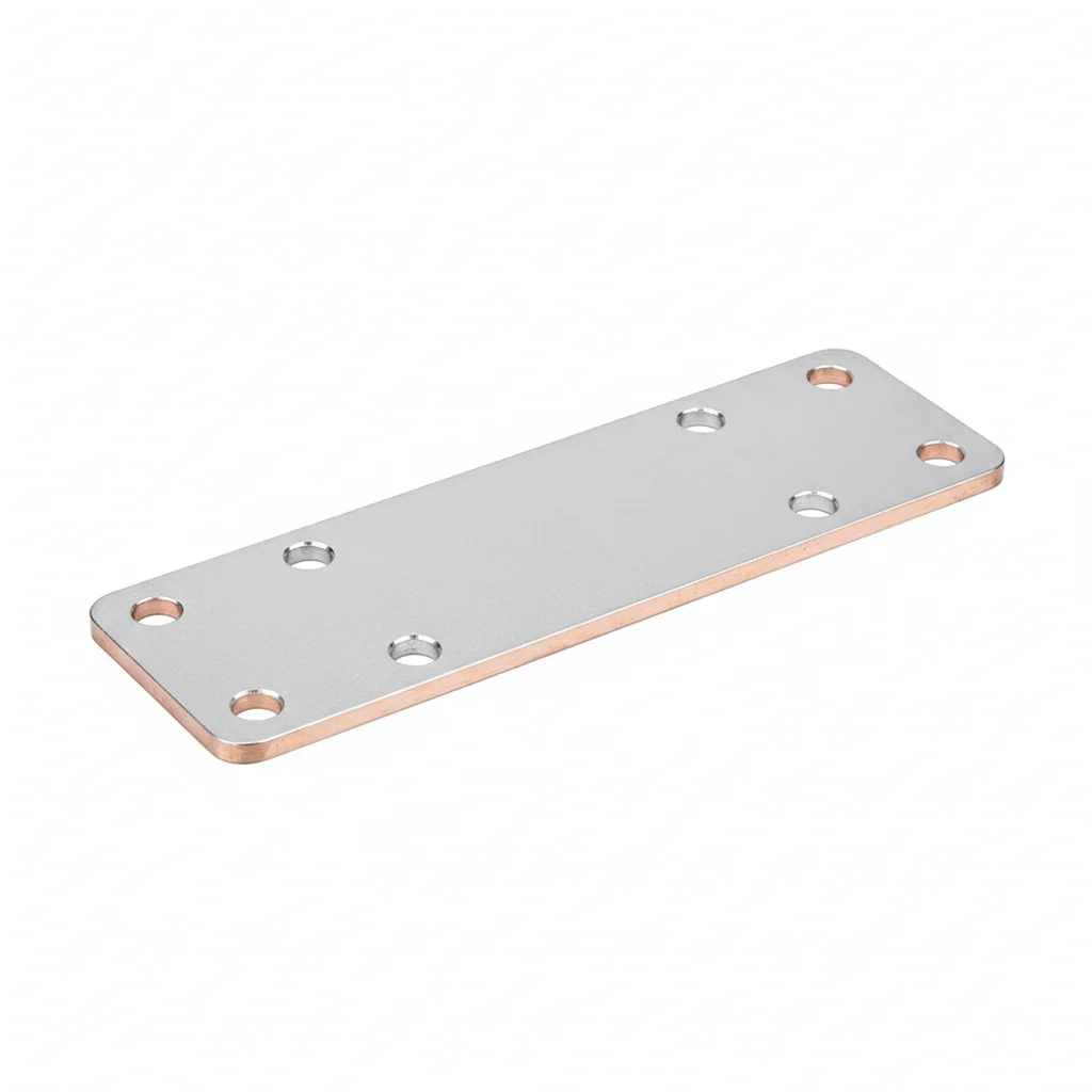
| Combiner Box Mounting Screw Set | Combiner Box Triangular Lock | Combiner Box Stainless Steel Hinge | Sealing Strip | Grounding Copper Busbar | |
|---|---|---|---|---|---|
| SPEC | M4/M5/M6 × Cross Recessed Pan Head | Universal Triangular Lock Core | 50×50mm × 2.0mm Thick | 15×20mm Hollow Structure | 5×20×150mm |
| MATERIAL | 304 Stainless Steel A2-70 | Zinc Alloy Lock Core + 304 Stainless Steel Lock Body | 304 Stainless Steel | EPDM Rubber | T2 Copper, Tin Plated (Coating ≥8μm) |
| GRADE | Plain | Chrome Plated | Plain | Black, Temperature Range -40~120°C | Tin Plated |
| FINISH | HDG >=55um per ISO 1461 | HDG >=55um per ISO 1461 | HDG >=55um per ISO 1461 | HDG >=55um per ISO 1461 | HDG >=55um per ISO 1461 |
| CORROSION | C3 (ISO 12944-2) | C3 (ISO 12944-2) | C3 (ISO 12944-2) | Not applicable (polymer) | C3 (ISO 12944-2) |
| TEMP | -20°C to +80°C | -20°C to +80°C | -20°C to +80°C | -20°C to +80°C | -20°C to +80°C |
| WEIGHT | ~0.5 kg/piece | ~0.5 kg/piece | ~0.5 kg/piece | ~0.5 kg/piece | ~0.5 kg/piece |
| MOQ | 100 pcs | 100 pcs | 100 pcs | 100 pcs | 100 pcs |
| PACK | VCI paper + carton | VCI paper + carton | VCI paper + carton | VCI paper + carton | VCI paper + carton |
| STD | ISO 898-1, GB/T 3098.1 | ISO 898-1, GB/T 3098.1 | ISO 898-1, GB/T 3098.1 | ISO 898-1, GB/T 3098.1 | ISO 898-1, GB/T 3098.1 |
| USE | Mounting and fixing internal box components | Box door locking, waterproof and dustproof cap seal | Box door hinging, load capacity 15kg/pair | Waterproof seal between box door and body | String grounding aggregation, with M6 grounding bolt |
PROCEDURE
- Clean the box door contact surfaces and hinge mounting points, removing any debris or oxidation before fitting the 304 stainless steel components.
- Align the 50×50mm hinge with the door frame, insert the M6 mounting screws, and hand-tighten before final adjustment.
- Tighten all M4/M5/M6 screws in a cross pattern to ensure even pressure on the EPDM sealing strip.
- Install the triangular lock, ensuring the zinc alloy core turns freely and the 304 stainless steel body seats flush against the door.
- Verify the sealing strip compresses evenly along the entire door perimeter; adjust hinge position if gaps appear.
COMMON ERRORS
| ✕ WRONG | CONSEQUENCE | ✓ CORRECT |
|---|---|---|
| Using carbon steel screws instead of 304 stainless steel A2-70 for internal mounting | Corrosion in C3 outdoor conditions seizes the screw heads within 2-3 years, making disassembly for maintenance impossible. | Use 304 stainless steel A2-70 screws rated for C3 per ISO 12944-2 for all internal box component fixings. |
| Overtightening the triangular lock mounting screws, compressing the lock body | The lock core binds and the door cannot be opened, forcing cutting of the lock during inspection. | Tighten the lock mounting screws to a firm hand-tight plus a quarter turn, allowing the lock core to rotate freely. |
MAINTENANCE
During each seasonal inspection, press the EPDM sealing strip to check for rebound and inspect for surface cracks; replace if hardened or indented. Verify hinge pins show no rust and operate smoothly. At the 5-year inspection, measure the sealing strip thickness and compare to the original 15×20mm profile, replacing if compression set exceeds 30%.
Plan B · High Protection Enhanced Configuration
C4 Harsh per ISO 12944-2
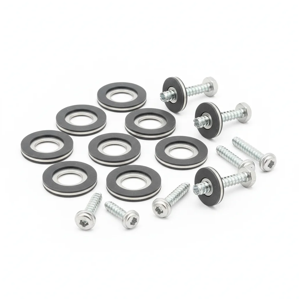
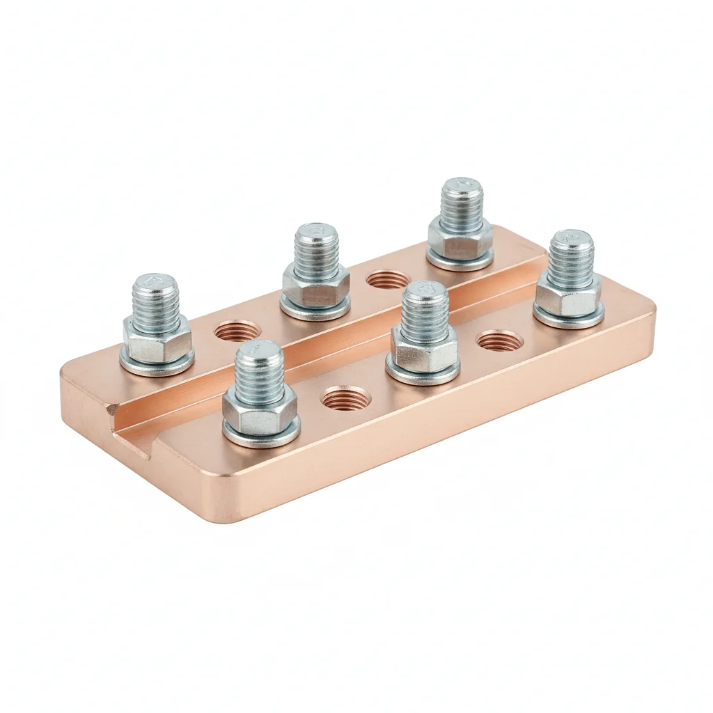
| Screw Set | Combiner Box Handle Lock | Hinge | Reinforced EPDM Sealing Strip | Reinforced Grounding Copper Busbar | |
|---|---|---|---|---|---|
| SPEC | M4/M5/M6 | With Rotating Handle | 60×60mm × 2.5mm | 20×25mm Three-Chamber Hollow | 10×30×200mm |
| MATERIAL | 316 Stainless Steel A4-70 | 316 Stainless Steel | 316 Stainless Steel | EPDM Rubber | T2 Copper, Tin + Nickel Underlayer Plated |
| GRADE | Plain | Plain | Plain | Black, Salt Spray Resistance 2000h | Tin Plated |
| FINISH | HDG >=55um per ISO 1461 | HDG >=55um per ISO 1461 | HDG >=55um per ISO 1461 | HDG >=55um per ISO 1461 | HDG >=55um per ISO 1461 |
| CORROSION | C3 (ISO 12944-2) | C3 (ISO 12944-2) | C3 (ISO 12944-2) | Not applicable (polymer) | C3 (ISO 12944-2) |
| TEMP | -20°C to +80°C | -20°C to +80°C | -20°C to +80°C | -20°C to +80°C | -20°C to +80°C |
| WEIGHT | ~0.5 kg/piece | ~0.5 kg/piece | ~0.5 kg/piece | ~0.5 kg/piece | ~0.5 kg/piece |
| MOQ | 100 pcs | 100 pcs | 100 pcs | 100 pcs | 100 pcs |
| PACK | VCI paper + carton | VCI paper + carton | VCI paper + carton | VCI paper + carton | VCI paper + carton |
| STD | ISO 898-1, GB/T 3098.1 | ISO 898-1, GB/T 3098.1 | ISO 898-1, GB/T 3098.1 | ISO 898-1, GB/T 3098.1 | ISO 898-1, GB/T 3098.1 |
| USE | Replacement for 304 in coastal/chemical pollution environments | Door lock for large combiner boxes, easy to operate with gloves | Box door hinging for C5 environment | Coastal high-humidity environment, three-chamber sealing redundant design | Large combiner box grounding, dual bolt connection |
PROCEDURE
- Clean mating surfaces with a solvent suitable for 316 stainless steel, ensuring no oily residue remains before assembly.
- Fit the 316 SS screws (A4-70) with flat and spring washers, then align the 60×60mm hinge and handle lock before tightening.
- Torque M6 screws to 6-8 Nm in a cross pattern, using a calibrated wrench; for the dual-bolt busbar connection, torque both M6 bolts evenly.
- Press the reinforced EPDM strip (20×25mm three-chamber) into the groove, ensuring no kinks and full contact along the perimeter.
- After mounting the door, test the handle lock operation with gloves and verify the sealing strip compresses uniformly when closed.
COMMON ERRORS
| ✕ WRONG | CONSEQUENCE | ✓ CORRECT |
|---|---|---|
| Reusing 304 SS screws in a coastal C4 environment | Pitting corrosion initiates within months, leading to seized threads and compromised door sealing. | Use 316 SS (A4-70) screws specified for coastal areas, and discard any 304 hardware from the BOM. |
| Overtightening the handle lock mounting bolts | Distorts the lock housing, causing the handle to bind and the sealing strip to deform, reducing IP protection. | Tighten to the recommended 6-8 Nm for M6, and verify smooth handle rotation after installation. |
MAINTENANCE
Inspect the reinforced EPDM sealing strip seasonally for cracks or compression set; replace if finger-press leaves an indentation. Check the 316 SS handle lock and hinge for salt buildup or pitting at each scheduled maintenance window. Re-torque grounding busbar bolts to 6-8 Nm during annual infrared thermography inspections.
Plan C · Extreme Environment/Export Configuration
C5-M Extreme per ISO 12944-2
| Screw Set | IEC Certified Combiner Box Lock | Hinge | Sealing Strip | Grounding Copper Busbar | |
|---|---|---|---|---|---|
| SPEC | M4-M6 | Certified Grade Dual Point Locking | 60×60mm Removable Pin | 15×20mm | 10×30mm + Silver-based Conductive Paste |
| MATERIAL | 316L Stainless Steel A4-80 | 316L Stainless Steel | 316L Stainless Steel | EPDM Rubber | T2 Copper, Silver Plated |
| GRADE | Electropolished | IP66 | Electropolished | Temperature Range -40~250°C, Salt Spray Resistance 5000h | Silver Plated |
| FINISH | HDG >=55um per ISO 1461 | HDG >=55um per ISO 1461 | HDG >=55um per ISO 1461 | HDG >=55um per ISO 1461 | HDG >=55um per ISO 1461 |
| CORROSION | C3 (ISO 12944-2) | C3 (ISO 12944-2) | C3 (ISO 12944-2) | Not applicable (polymer) | C3 (ISO 12944-2) |
| TEMP | -20°C to +80°C | -20°C to +80°C | -20°C to +80°C | -20°C to +80°C | -20°C to +80°C |
| WEIGHT | ~0.5 kg/piece | ~0.5 kg/piece | ~0.5 kg/piece | ~0.5 kg/piece | ~0.5 kg/piece |
| MOQ | 100 pcs | 100 pcs | 100 pcs | 100 pcs | 100 pcs |
| PACK | VCI paper + carton | VCI paper + carton | VCI paper + carton | VCI paper + carton | VCI paper + carton |
| STD | ISO 898-1, GB/T 3098.1 | ISO 898-1, GB/T 3098.1 | ISO 898-1, GB/T 3098.1 | ISO 898-1, GB/T 3098.1 | ISO 898-1, GB/T 3098.1 |
| USE | Offshore platform combiner box, highest corrosion protection level | Export projects to Europe/America, meets IEC 61439 certification | Offshore environment, removable for easy maintenance | Extreme environments: offshore platforms, chemical plant surroundings | Export project grounding, silver-based conductive paste ensures contact resistance |
PROCEDURE
- Degrease all 316L components with an approved solvent and passivate the surfaces to maximize corrosion resistance.
- Apply silver-based conductive paste to the grounding busbar contact area before securing with the M6 bolt.
- Install the IP66 dual-point lock and removable-pin hinge using 316L screws (A4-80), torquing M6 fasteners to 6-8 Nm.
- Fit the FFKM sealing strip (rated -40~250°C) into the groove, ensuring it seats without twisting for continuous compression.
- Perform a functional test of the lock and hinge, then verify the door seal integrity by checking for uniform gap around the perimeter.
COMMON ERRORS
| ✕ WRONG | CONSEQUENCE | ✓ CORRECT |
|---|---|---|
| Using standard EPDM instead of FFKM in offshore salt-laden air | Accelerated degradation of the seal leads to water ingress and electrical faults within a short period. | Specify FFKM sealing strip with 5000h salt spray resistance for C5-M environments. |
| Skipping conductive paste on the silver-plated busbar | Micro-gaps increase contact resistance, causing overheating and ground fault risk despite the silver plating. | Apply silver-based conductive paste to the busbar contact surface before tightening the grounding bolt. |
MAINTENANCE
Inspect the FFKM seal and 316L hardware at each major overhaul window, looking for any signs of chloride stress corrosion. Verify the IP66 lock mechanism operates smoothly and the hinge pin remains free. Reapply silver-based conductive paste and re-torque grounding bolts to 6-8 Nm during annual thermographic inspections.
SELECTION GUIDE
Which combiner box hardware plan fits your site conditions?
| Operating condition | Recommended option | Key basis |
|---|---|---|
| Coastal / high-temperature / high-rainfall area | Plan B Stainless Steel (316 A4-70) + reinforced EPDM sealing strip | Environment class C4-C5 per ISO 12944-2, salt spray resistance ≥2000h per ASTM D395 |
| Export to Europe/America requiring IEC 61439 certification | Plan C Full Range Certified Components (316L A4-80) | IEC 61439 type test certification, IP66 rated lock, salt spray quality 5000h |
| Inland small distributed project (under 500kW) | Plan A (304 A2-70 stainless steel + EPDM sealing strip) | Environment class C3 per ISO 12944-2, meets 25-year service life |
REFERENCED STANDARDS
Referenced Standards & Authoritative References
Core standard for combiner box type testing and protection rating, IP level requirements are specified by this standard.
Copper, aluminium and their alloy bus bars for electrical purposes – Part 1: Copper and copper alloy bus barsRequirements for material, dimensions, and electrical performance of grounding copper busbars.
Cable glands for electrical installationsMechanical and sealing performance standard for cable glands.
Mechanical properties of corrosion-resistant stainless steel fastenersBasis for selecting strength grades of 304/316/316L stainless steel screws.
Standard Test Methods for Rubber Property—Compression SetTest standard for compression recovery performance of EPDM sealing strips.
Low-voltage switchgearSUPPLIER CAPABILITY
Quality, Delivery & Customization
Quality Control
- ✓MTC material certificates with every batch
- ✓Key parts sampled for hardness/salt spray/torque coefficient
- ✓100% inspection or AQL sampling before shipment
Delivery
- ✓Standard parts made to order: 7-15 days
- ✓Custom parts: 25-45 days
- ✓FOB/CIF/DDP supported
Customization
- ✓Drawing review and material matching
- ✓Non-standard sizes/heads/threads
- ✓Small-batch prototyping supported
Certification
- ✓Material certificates (MTC)
- ✓Spectrographic analysis reports
- ✓Salt spray test reports (on request)
MOQ: No MOQ for standard parts; custom parts assessed by process complexity
FAQ
Frequently Asked Questions
RELATED READING
Keep Reading & Next Step
NEXT: SELECTION & RFQ
PV Electrical ConnectorsFollow this page's selection path to the same-scenario RFQ page.
RELATED TOPIC
PV DC CablesRELATED TOPIC
Inverter Mounting BracketsBEYOND TECHNICAL SPECS
Finding the right factory, controlling quality, delivering on time — that's the real challenge. We cover fasteners, rubber, plastics, industrial textiles. One team, end to end.
SEE CAPABILITIES →