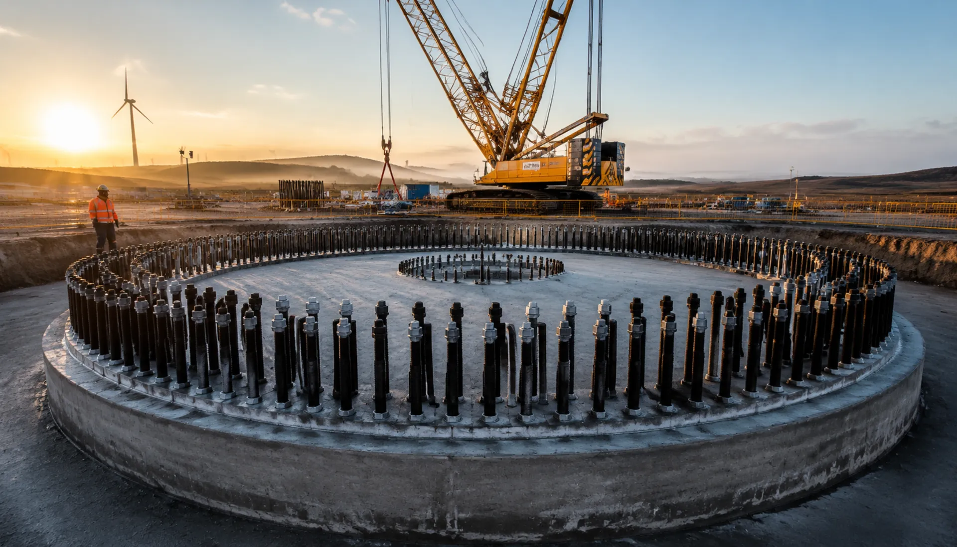
Wind Turbine Anchor Cage: Onshore vs Offshore Selection
Anchor cages fix the tower to concrete foundations, resisting overturning moment and shear. Onshore cages use 42CrMoA bolts with HDG ≥85μm; offshore cages use 34CrNiMo6 with thermal spray aluminum + epoxy ≥320μm. Compare materials, coatings, and corrosion protection to match your project environment
FIELD-SPECIFIC INSIGHT
Anchor Cage Material & Coating: Critical Differences for Procurement
Onshore and offshore anchor cages differ in bolt material, coating system, and corrosion protection strategy. Onshore uses 42CrMoA with HDG ≥85μm; offshore uses 34CrNiMo6 with thermal spray aluminum + epoxy ≥320μm. The wrong choice can lead to premature corrosion or bolt failure
WHAT TO CHECK
- 1Onshore anchor bolts: 42CrMoA, HDG ≥85μm, suitable for C3 environment per ISO 12944-2
- 2Offshore anchor bolts: 34CrNiMo6, thermal spray aluminum + epoxy ≥320μm, for C4 harsh environment
- 3Offshore bolts are larger (M56-M72 vs M48-M64) and longer (3-7m vs 2-5m) to handle wave loads
- 4Offshore requires corrosion protection sleeves (PE/HDPE) on exposed bolt sections; onshore does not
- 5Prestressed anchor cages (for >8MW turbines) apply initial tension 200-400kN/bolt and require 100% UT inspection
| Check | Why it matters | What to specify |
|---|---|---|
| Bolt material and grade | Onshore 42CrMoA 10. 9S vs offshore 34CrNiMo6 10. 9S; offshore alloy offers better toughness in cold, corrosive marine environment | Specify material grade and mechanical properties per ISO 898-1 |
| Coating system and thickness | HDG ≥85μm for onshore; thermal spray aluminum + epoxy ≥320μm for offshore. Insufficient coating leads to early corrosion | Specify coating per ISO 1461 (HDG) or ISO 2063 (thermal spray) plus epoxy topcoat; require thickness measurement report |
| Corrosion protection for exposed threads | Offshore bolts above concrete need PE/HDPE sleeves to prevent chloride attack; onshore bolts are fully embedded | For offshore, require corrosion protection sleeve material (PE100) and installation method |
| Preload and tension control | Offshore must account for wave loads; prestressed cages require initial tension 200-400kN/bolt. Incorrect preload causes fatigue | Specify preload torque per EN 14399 or DNV-ST-0126; for prestressed, require UT inspection of 100% bolts |
All coating thickness values and material grades are from the page data. Verify with project-specific corrosion category and design life
Evidence level: source-page-only
RISK AUDIT // ENGINEERING DIAGNOSIS
Procurement Pitfall Avoidance Guide
"Anchor cage misalignment, carbonation-induced cracking, and bolt loosening are the top field failures we address."
QC-AUDIT // REV.5
SCALE 1:1 · 03 ITEMS
RISK-01
Anchor Cage Embedment Deviation Leads to Misalignment
Corrective Measures
RISK-02
Anchor Cage Reinforcement Rust Expansion and Concrete Cracking After Carbonation
Corrective Measures
✅ Before installation, coat the threaded section with grease or brush on anti-rust oil and wrap with a plastic protective cap.2. ✅ Immediately after pouring, flush exposed threads with a high-pressure water jet (within <30 minutes).3. ✅ Use fully threaded anchor bolts (GB/T 3098.1 Class 10.9) to reduce dead pockets where slurry can lodge.4. ✅ Pre-embed anchor bolts in one pour with the foundation concrete (set in the formwork before concreting); where post-installation is unavoidable, fill reserved holes solid with pre-mixed non-shrink grout to prevent secondary slurry ingress into the threads.RISK-03
Foundation Ring Bolts Loosen Under Impact from Turbine Start-Stop Cycles
Corrective Measures
INDUSTRY TECH REFERENCE
Three Pre-Lift Checks: Position, Flatness, Trial Fit
Run these three checks before the tower lift, and most foundation-joint problems surface before the crane moves.
- Flange-face flatness ≤0.5 mm/m (per GB/T 19072) — out-of-flat means uneven bolt loading; measure it at acceptance
- Face roughness Ra 6.3–12.5 μm, shear transferred by friction — a wrong roughness will not hold shear no matter how tight
- Re-survey the anchor group with a total station and trial-fit every bolt before lifting — fixing out-of-tolerance deviations on the tower means field reaming or rework
INDUSTRY TECH REFERENCE
Offshore Tower-Base Parts: Splash-Zone and Underwater Fittings
The anchor cage is only part of an offshore tower base — splash-zone and underwater corrosion parts follow this sheet, and size plus material decide what fails first within the 25–30-year life.
| Part | Size | Material | Key specs |
|---|---|---|---|
| Transition-piece inspection platform bolts | M16–M24 | 2205 | Harshest in the splash zone |
| Subsea cable J-tube fittings | M12–M20 | 316L | Underwater cathodic-protection zone |
| Sacrificial-anode fixing bolts | M16–M20 | 316L | Replaced periodically |
| Tower-base underwater section | — | — | Needs cathodic protection: sacrificial anodes or impressed current |
Sizes and materials follow the industry scene-spec table; the 25–30-year life is an industry magnitude; verify per project drawings and DNV-ST-0126.
INDUSTRY TECH REFERENCE
From Embedment Deviation to Fatigue Fracture
Anchor-cage failures rarely start with the material — an embedment deviation left unhandled travels all the way to fracture.
- 1Lateral pressure and vibration during pouring shift the anchor bolts — the tower flange holes no longer line up
- 2Forcing the fit loads the bolts in eccentric tension, concentrating stress at the thread root
- 3Under wind-load cycles the stress alternates, and cracks start at the thread root or surface defects
- 4Fracture comes without warning, and the anchor bolts are buried in concrete — invisible to routine visual checks
- 5Prevention: re-survey and trial-fit before the lift, then scheduled UT/MT inspection in service
The page's embedment tolerance figures (>5 mm centerline, >10 mm elevation, ±2 mm allowed) have no KB basis and are not used; the chain relies on KB-sourced mechanisms only.
INDUSTRY TECH REFERENCE
Standards for Wind Foundations and Towers
Reference these standards when specifying and accepting anchor cages:
Standards listed for navigation; acceptance criteria per the official texts.
PLAN COMPARISON
Three-Plan Core Parameter Comparison
Compare row by row. Click column headers to jump to plan details.
| A · ① Onshore Anchor Cage | B · ② Offshore Anchor Cage | C · ③ Prestressed Anchor Cage | |
|---|---|---|---|
| 1. ANCHOR BOLT | |||
| SPEC | M48-M64, L=2-5m | M56-M72, L=3-7m | M48-M64, L=2-5m |
| MATERIAL | 42CrMoA, Hot-dip Galvanized ≥85μm | 34CrNiMo6, Thermal Spray Aluminum + Epoxy ≥320μm | 42CrMoA, Hot-dip Galvanized ≥85μm |
| GRADE | 10.9S | 10.9S | 10.9S |
| FINISH | HDG >=55um per ISO 1461 | HDG >=55um per ISO 1461 | HDG >=55um per ISO 1461 |
| 2. UPPER ANCHOR PLATE | |||
| SPEC | t=40-80mm | t=60-120mm | t=40-80mm |
| MATERIAL | Q345B, Hot-dip Galvanized | Q345B, Thermal Spray Aluminum + Epoxy | Q345B, Hot-dip Galvanized |
| FINISH | HDG >=55um per ISO 1461 | HDG >=55um per ISO 1461 | HDG >=55um per ISO 1461 |
| 3. LOWER ANCHOR PLATE | |||
| SPEC | t=30-60mm | PE/HDPE | t=30-60mm |
| MATERIAL | Q345B | PE100 | Q345B |
| FINISH | HDG >=55um per ISO 1461 | HDG >=55um per ISO 1461 | HDG >=55um per ISO 1461 |
| 4. LEVELING FOOT | |||
| SPEC | M30-M42, Adjustable ±50mm | M10-M12 | M30-M42, Adjustable ±50mm |
| MATERIAL | 42CrMoA | 304 Stainless | 42CrMoA |
| GRADE | 8.8 | A2 | 12.9 |
| FINISH | HDG >=55um per ISO 1461 | Passivated | HDG >=55um per ISO 1461 |
| 5. FLAT WASHER | |||
| SPEC | M10-M12 | M10-M12 | Accessory |
| MATERIAL | 304 Stainless | 304 Stainless | — |
| GRADE | A2 | A2 | — |
| FINISH | Passivated | Passivated | HDG >=55um per ISO 1461 |
① Onshore Anchor Cage
C3 (ISO 12944-2) with HDG ≥85μm per ISO 1461
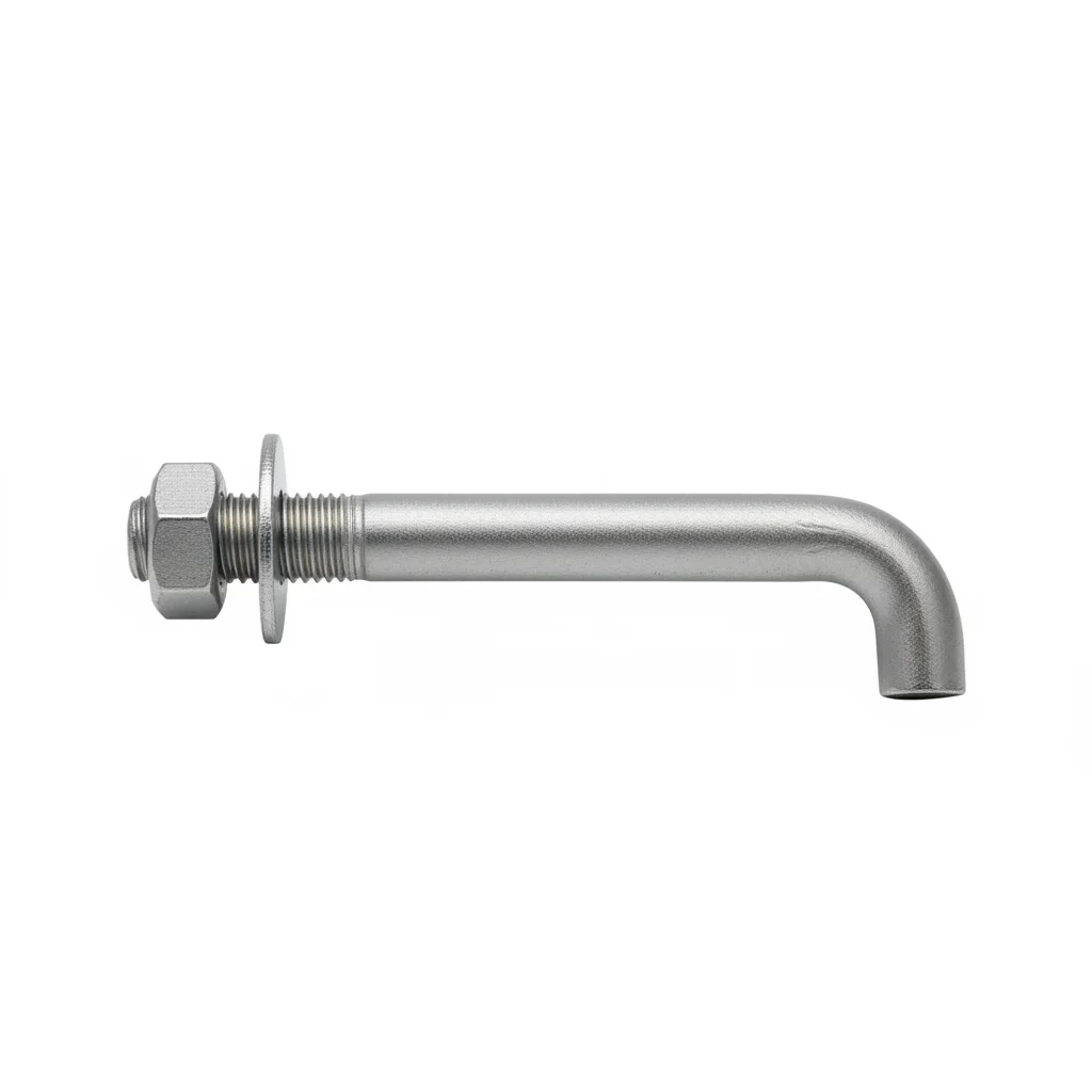
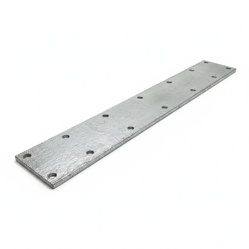
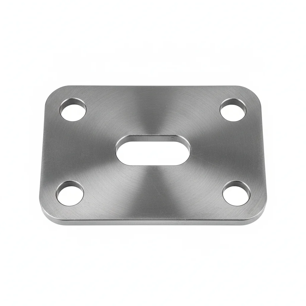
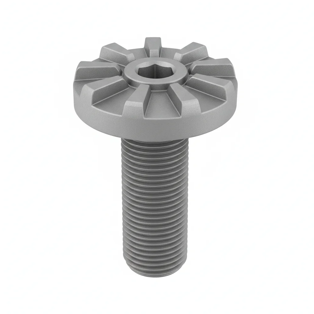
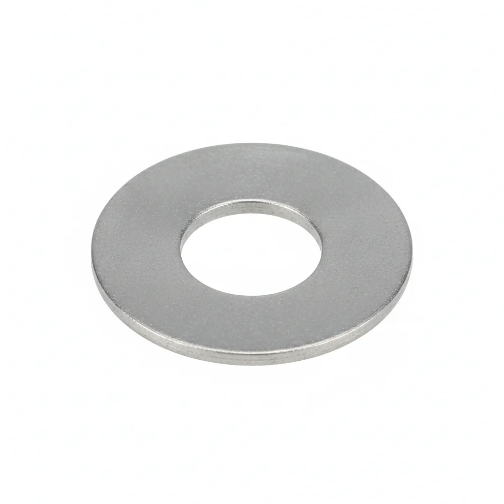
| Anchor Bolt | Upper Anchor Plate | Lower Anchor Plate | Leveling Foot | Flat Washer | |
|---|---|---|---|---|---|
| SPEC | M48-M64, L=2-5m | t=40-80mm | t=30-60mm | M30-M42, Adjustable ±50mm | M10-M12 |
| MATERIAL | 42CrMoA, Hot-dip Galvanized ≥85μm | Q345B, Hot-dip Galvanized | Q345B | 42CrMoA | 304 Stainless |
| GRADE | 10.9S | — | — | 8.8 | A2 |
| FINISH | HDG >=55um per ISO 1461 | HDG >=55um per ISO 1461 | HDG >=55um per ISO 1461 | HDG >=55um per ISO 1461 | Passivated |
| CORROSION | C3 (ISO 12944-2) | C3 (ISO 12944-2) | C3 (ISO 12944-2) | C3 (ISO 12944-2) | C3 (ISO 12944-2) |
| TEMP | -20°C to +80°C | -20°C to +80°C | -20°C to +80°C | -20°C to +80°C | -20°C to +80°C |
| WEIGHT | ~0.5 kg/piece | ~0.5 kg/piece | ~0.5 kg/piece | ~0.5 kg/piece | ~0.005kg |
| MOQ | 100 pcs | 100 pcs | 100 pcs | 100 pcs | 500 pcs |
| PACK | VCI paper + carton | VCI paper + carton | VCI paper + carton | VCI paper + carton | Plastic bag |
| STD | ISO 898-1, GB/T 3098.1 | ISO 898-1, GB/T 3098.1 | ISO 898-1, GB/T 3098.1 | ISO 898-1, GB/T 3098.1 | ISO 7089 |
| USE | Tower Foundation Fixing | Bearing Under Tower Flange | Foundation Bottom Anchoring | Tower Verticality Adjustment | Load distribution |
PROCEDURE
- Prepare the embedment: verify the positioning plate hole positions are within ±2mm tolerance before concrete pour.
- Set the 42CrMoA anchor bolts (M48-M64) into the cage, securing with Q345B upper/lower plates and leveling feet adjusted to ±50mm.
- After concrete cures, tension bolts in a star pattern to the preload specified per EN 14399, using hydraulic tensioners for accuracy.
- Inspect the exposed threads and galvanized surfaces for damage; touch up any areas with zinc-rich paint to maintain ≥85μm protection.
- Record final preload values and mark bolts for visual verification during service.
COMMON ERRORS
| ✕ WRONG | CONSEQUENCE | ✓ CORRECT |
|---|---|---|
| Using a torque wrench instead of a hydraulic tensioner for M48-M64 anchor bolts. | Torque coefficient is unstable for large bolts, leading to inconsistent preload and potential joint loosening under cyclic loads. | Employ hydraulic tensioners to achieve precise preload control, as specified for 10.9S grade bolts. |
| Ignoring positioning plate tolerance during installation. | Anchor bolt deviation exceeds ±2mm, preventing tower flange alignment and requiring costly rework. | Use double-layer positioning templates and real-time monitoring during concrete pouring to keep deviation below 2%. |
MAINTENANCE
Seasonally, check torque on a sample of bolts and re-tension any that have lost more than 15% of specified preload. Inspect for corrosion on exposed threads and re-apply protective coating if HDG thickness falls below 85μm.
② Offshore Anchor Cage
C5-M (ISO 12944-2) for offshore splash zone with 34CrNiMo6 and thermal spray aluminum + epoxy ≥320μm
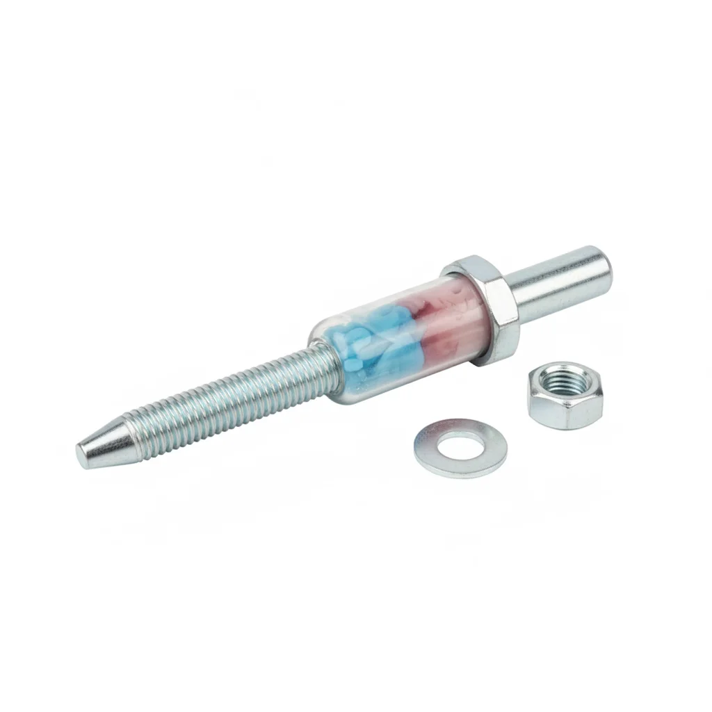
| Anchor Bolt | Upper Anchor Plate | Corrosion Protection Sleeve | Flat Washer | Flat Washer | |
|---|---|---|---|---|---|
| SPEC | M56-M72, L=3-7m | t=60-120mm | PE/HDPE | M10-M12 | M10-M12 |
| MATERIAL | 34CrNiMo6, Thermal Spray Aluminum + Epoxy ≥320μm | Q345B, Thermal Spray Aluminum + Epoxy | PE100 | 304 Stainless | 304 Stainless |
| GRADE | 10.9S | — | — | A2 | A2 |
| FINISH | HDG >=55um per ISO 1461 | HDG >=55um per ISO 1461 | HDG >=55um per ISO 1461 | Passivated | Passivated |
| CORROSION | C3 (ISO 12944-2) | C3 (ISO 12944-2) | C3 (ISO 12944-2) | C3 (ISO 12944-2) | C3 (ISO 12944-2) |
| TEMP | -20°C to +80°C | -20°C to +80°C | -20°C to +80°C | -20°C to +80°C | -20°C to +80°C |
| WEIGHT | ~0.5 kg/piece | ~0.5 kg/piece | ~0.5 kg/piece | ~0.005kg | ~0.005kg |
| MOQ | 100 pcs | 100 pcs | 100 pcs | 500 pcs | 500 pcs |
| PACK | VCI paper + carton | VCI paper + carton | VCI paper + carton | Plastic bag | Plastic bag |
| STD | ISO 898-1, GB/T 3098.1 | ISO 898-1, GB/T 3098.1 | ISO 898-1, GB/T 3098.1 | ISO 7089 | ISO 7089 |
| USE | Offshore Tower Foundation | Bearing Under Tower Flange | Corrosion Protection for Exposed Bolt Section | Load distribution | Load distribution |
PROCEDURE
- Clean M56-M72 34CrNiMo6 threads and bearing faces with acetone; verify surface roughness Ra below 3.2 μm per ISO 2063.
- Slide the PE100 corrosion protection sleeve over the exposed bolt shank before positioning the anchor cage in the formwork.
- Screw on the nut with a calibrated torque wrench, then tension hydraulically to the preload specified in DNV-ST-0126 to account for wave loads.
- Verify verticality of the anchor cage within ±2 mm using the positioning template before concrete pour.
- After concrete cures, re-tension the bolting to the design preload and seal the top of the sleeve with the epoxy topcoat.
COMMON ERRORS
| ✕ WRONG | CONSEQUENCE | ✓ CORRECT |
|---|---|---|
| Leaving the PE100 sleeve off the exposed thread section during installation | Salt spray reaches the 34CrNiMo6 surface and initiates pitting corrosion, reducing fatigue life below the 30-year design life. | Install the full-length PE100 sleeve over the exposed portion of every M56-M72 anchor bolt before assembly. |
| Tightening the offshore bolts with a torque wrench only, ignoring wave-load preload requirements | Preload falls below the DNV-ST-0126 requirement, allowing the flange to open under wave-induced bending moments and causing fatigue cracks. | Use a hydraulic tensioner to apply the preload calculated for wave loads, then verify with a load cell on a 10% sample. |
| Damaging the thermal spray aluminum + epoxy coating when positioning the cage | Bare 34CrNiMo6 is exposed to chloride-laden seawater, leading to rapid galvanic corrosion and loss of section within months. | Use soft slings and edge protectors during lifting; repair any coating damage with a zinc-rich primer and epoxy topcoat before concrete pour. |
MAINTENANCE
Annually inspect the exposed bolt section above the concrete for coating damage and check the PE100 sleeve integrity; re-tension any bolt that has lost more than 15% of its specified preload as measured by an ultrasonic stress meter. At each overhaul window, perform a full visual inspection of the thermal spray aluminum + epoxy system and repair any areas where the coating thickness has fallen below 320 μm.
③ Prestressed Anchor Cage
C5-M (ISO 12944-2) plus fatigue-critical prestress regime for >8MW turbines, 34CrNiMo6 with 100% UT inspection
| Anchor Bolt | Upper Anchor Plate | Lower Anchor Plate | Leveling Foot | Inspection & Maintenance Toolkit | |
|---|---|---|---|---|---|
| SPEC | M48-M64, L=2-5m | t=40-80mm | t=30-60mm | M30-M42, Adjustable ±50mm | Accessory |
| MATERIAL | 42CrMoA, Hot-dip Galvanized ≥85μm | Q345B, Hot-dip Galvanized | Q345B | 42CrMoA | — |
| GRADE | 10.9S | — | — | 12.9 | — |
| FINISH | HDG >=55um per ISO 1461 | HDG >=55um per ISO 1461 | HDG >=55um per ISO 1461 | HDG >=55um per ISO 1461 | HDG >=55um per ISO 1461 |
| CORROSION | C3 (ISO 12944-2) | C3 (ISO 12944-2) | C3 (ISO 12944-2) | C3 (ISO 12944-2) | C3 (ISO 12944-2) |
| TEMP | -20°C to +80°C | -20°C to +80°C | -20°C to +80°C | -20°C to +80°C | -20°C to +80°C |
| WEIGHT | ~0.5 kg/piece | ~0.5 kg/piece | ~0.5 kg/piece | ~0.5 kg/piece | ~0.5 kg/piece |
| MOQ | 100 pcs | 100 pcs | 100 pcs | 100 pcs | 100 pcs |
| PACK | VCI paper + carton | VCI paper + carton | VCI paper + carton | VCI paper + carton | VCI paper + carton |
| STD | ISO 898-1, GB/T 3098.1 | ISO 898-1, GB/T 3098.1 | ISO 898-1, GB/T 3098.1 | ISO 898-1, GB/T 3098.1 | ISO 898-1, GB/T 3098.1 |
| USE | Tower Foundation Fixing | Bearing Under Tower Flange | Foundation Bottom Anchoring | Tower Verticality Adjustment | Periodic Torque Verification |
PROCEDURE
- Degrease the M48-M72 34CrNiMo6 bolts with MEK and verify surface roughness Ra below 1.6 μm before applying the hot-dip galvanized coating ≥85 μm.
- Set the anchor cage using double-layer positioning templates to keep hole positions within ±2 mm; monitor for displacement during the concrete pour.
- After concrete reaches design strength, tension each bolt to the specified initial preload of 200-400 kN using a hydraulic tensioner.
- Perform 100% ultrasonic testing (UT) of the bolts to confirm preload and detect any flaws; record results for the QA file.
- Mark the bolts with a torque seal and install the corrosion monitoring instrumentation on a sample of bolts for long-term data logging.
COMMON ERRORS
| ✕ WRONG | CONSEQUENCE | ✓ CORRECT |
|---|---|---|
| Skipping the 100% UT inspection on a prestressed anchor bolt | An undetected internal flaw in the 34CrNiMo6 bolt propagates under the 200-400 kN preload and cyclic wind loads, leading to sudden brittle fracture. | Perform 100% UT inspection on all M48-M72 prestressed bolts and replace any bolt showing crack indications. |
| Using a torque wrench instead of a hydraulic tensioner to reach the 200-400 kN preload | Torque control is unreliable for large-diameter bolts, causing scatter in preload; some bolts may fall below the required tension, leading to foundation cracking. | Tension hydraulically to the specified preload and verify with a load cell on a 10% sample; document values for compliance audit. |
| Allowing the anchor cage to shift more than ±2 mm during concrete pouring | The bolts no longer align with the tower flange holes, requiring flame cutting that reduces the bearing area by 15-30% and compromises the joint. | Use double-layer positioning templates and real-time monitoring to keep displacement below 2% of the specified tolerance. |
MAINTENANCE
In the first year, re-tension the prestressed bolts three times: 28 days after pouring, at 3 months, and at 12 months, to compensate for concrete shrinkage and preload decay. Thereafter, check preload annually with an ultrasonic bolt stress meter and re-tension any bolt that has lost more than 15% of its specified preload. At each overhaul window, perform a full disassembly inspection of a 20% sample and replace any bolt with corrosion pitting deeper than 0.3 mm.
SELECTION GUIDE
Anchor Cage Selection Decision Aid
| Operating condition | Recommended option | Key basis |
|---|---|---|
| Onshore wind farm | ① Onshore Anchor Cage — 42CrMoA M48-M64 (L=2-5m), Q345B anchor plates, HDG ≥85μm per ISO 1461, grade 10.9S | C3 (ISO 12944-2); preload per EN 14399 |
| Offshore wind farm (C5-M splash zone) | ② Offshore Anchor Cage — 34CrNiMo6 M56-M72 (L=3-7m), thermal spray aluminum + epoxy ≥320μm, PE100 corrosion protection sleeve | C5-M (ISO 12944-2); coating per ISO 2063; DNV-ST-0126 certified |
| High-power turbine (>8MW) | ③ Prestressed Anchor Cage — initial tension 200-400kN/bolt, 100% UT inspection | Load per EN 14399 or DNV-ST-0126 |
| Confirm project conditions (onshore/offshore, temperature range, vibration level) | Fix the application first, then pick the corrosion category and plan | ISO 12944-2 corrosion category |
| Load calculation and specification | Select specification per EN 14399 or DNV standards | EN 14399, DNV-ST-0126 |
| Corrosion protection scheme | Choose coating system per ISO 12944: HDG ≥85μm onshore; thermal spray aluminum + epoxy ≥320μm offshore | ISO 12944, ISO 1461 (HDG), ISO 2063 (thermal spray) |
REFERENCED STANDARDS
Technical Basis & Reference Standards
High-Strength Structural Bolting Assemblies
Wind Turbine Generator System Wind Farm Design RequirementsOffshore Wind Turbine Structure Design
Wind Turbine Tower and Foundation Design RequirementsCorrosion Protection of Steel Structures by Protective Paint Systems
Code for Design of Concrete StructuresSUPPLIER CAPABILITY
Quality, Delivery & Customization
Quality Control
- ✓MTC material certificates with every batch
- ✓Key parts sampled for hardness/salt spray/torque coefficient
- ✓100% inspection or AQL sampling before shipment
Delivery
- ✓Standard parts made to order: 7-15 days
- ✓Custom parts: 25-45 days
- ✓FOB/CIF/DDP supported
Customization
- ✓Drawing review and material matching
- ✓Non-standard sizes/heads/threads
- ✓Small-batch prototyping supported
Certification
- ✓Material certificates (MTC)
- ✓Spectrographic analysis reports
- ✓Salt spray test reports (on request)
MOQ: No MOQ for standard parts; custom parts assessed by process complexity
FAQ
Frequently Asked Questions
RELATED READING
Keep Reading & Next Step
NEXT: SELECTION & RFQ
Tower Cable Fixing ClampsFollow this page's selection path to the same-scenario RFQ page.
RELATED TOPIC
Transmission Fastener Incoming Inspection: The Checklist Passed Down by Senior Masters, Don't Skip ItBEYOND TECHNICAL SPECS
Finding the right factory, controlling quality, delivering on time — that's the real challenge. We cover fasteners, rubber, plastics, industrial textiles. One team, end to end.
SEE CAPABILITIES →