Wind Tower Cable Fixing: Failure Risks & Material Selection
A 3MW tower has hundreds of meters of vertical cables. Unfixed cables hit tower walls during sway, causing insulation damage and short circuits. Nylon ties become brittle above 60°C near the nacelle. Cable wear at bends and terminal stress from self-weight are common failure chains. A fixing point every 2-3m is the lowest cost prevention.
RISK AUDIT // ENGINEERING DIAGNOSIS
Procurement Pitfall Guide
"Why tower cable failures often trace back to fixing choices"
QC-AUDIT // REV.5
SCALE 1:1 · 03 ITEMS
RISK-01
Excessive Terminal Stress Due to Cable Self-Weight
Corrective Measures
RISK-02
Nylon Cable Ties Become Brittle and Break in High-Temperature Tower Sections
Corrective Measures
RISK-03
Severe Cable Wear at Cable Tray Bends
Corrective Measures
FIELD-SPECIFIC INSIGHT
Critical Checkpoints for Tower Cable Fixing
The most overlooked engineering difference in wind tower cable fixing is the temperature gradient: top tower sections near the nacelle can reach high temperatures, while the base is cooler. Using standard nylon ties in hot zones leads to brittleness within 2 years. Also, cable tray edges at bends must be chamfered to prevent sheath cutting.
WHAT TO CHECK
- 1Nylon ties (PA66+heat stabilizer) are suitable for tower sections below moderate temperatures; above that, use stainless steel clamps (304 or 316) to avoid brittleness and breakage.
- 2Cable bend radius at platform transitions must meet manufacturer minimums; use curved guide plates to prevent insulation cracking.
- 3Terminal stress from cable self-weight requires intermediate fixing every 2-3m to reduce tension on top terminals.
- 4In coastal/offshore environments, upgrade to 316/316L stainless steel to avoid corrosion that weakens clamps over long service life.
| Check | Why it matters | What to specify |
|---|---|---|
| Temperature at fixing location | Nylon ties become brittle at high temperatures, leading to breakage and cable release | Use stainless steel clamps (304 or 316) in top tower sections |
| Cable tray edge finish at bends | Sharp edges cut cable sheath during tower sway, causing insulation damage | Require chamfered edges or install curved guide plates |
| Fixing spacing | Wide spacing increases terminal stress and cable whip damage | Fix every 2-3m; verify with cable tension calculation |
| Corrosion protection class | Inadequate corrosion leads to clamp failure in coastal/offshore environments | Match ISO 12944-2 corrosion class; use 316L for offshore |
All material grades and corrosion classes must be verified against project-specific environmental conditions and turbine manufacturer specifications.
Evidence level: standard-backed
INDUSTRY TECH REFERENCE
The Duty List for Tower Cable Fixings
Cable fixings live inside the tower — know the duty before choosing material and life.
The 20–25/25–30-year design life is an industry magnitude; the top-section temperature gradient is qualitative, with no temperature figures.
INDUSTRY TECH REFERENCE
Tower Cable Fixing Small-Part Reference
Cable fixings are tower cable-tray/grating small parts — check size, material, and consumable status against this sheet.
| Component | Recommended size | Material | Duty / notes |
|---|---|---|---|
| Tower cable-tray bolts | M6–M12 | 304/316L | Humidity plus vibration is the rated duty; maintained for the tray's full life |
| Cable fixing clamp body | Per cable section | 304/hot-dip zinc inland; 316L/2205 offshore | Match the corrosivity class: C3–C4 inland, C5-M/CX offshore |
| Wedge lock washer | Per bolt size | Alloy steel | One set consumed at every retightening; restock against the retightening plan |
C3–C4/C5-M/CX and the 304/hot-dip zinc vs 316L/2205 small-part rule are KB-sourced.
INDUSTRY TECH REFERENCE
The First 100 Hours: Retightening and Locking for Cable Fixings
Cable clamps and clips look minor, but once preload is lost the cables start to chafe and whip. Run the rhythm on these lines.
- Fresh fixing bolts lose 10–15% of preload to embedding relaxation in the first 100 hours (magnitude estimate) — do not wait for the first annual inspection
- Retighten once 72–100 hours after installation (recommended); after that, run an annual inspection-and-retightening pass per the OEM manual
- Transverse tower vibration backs nuts off on its own (Junker mechanism) — spring washers cannot stop it; fit wedge lock washers on the fixings
- Do not let zinc-coated parts carry offshore duty: hot-dip zinc ≥85 μm lasts only 5–8 years offshore (magnitude estimate); move straight to 316L/2205
The 10–15% embedding relaxation and the 5–8-year offshore zinc life are magnitude estimates; 72–100 h retightening is recommended, annual inspection is industry practice.
INDUSTRY TECH REFERENCE
Micron-Scale Slip: How Fretting Grows Cracks
Every wind-load cycle slides the fixing contact faces against each other. Over time, cracks grow out of the pits.
- 1The tower sways under wind load, and trays, clips, and cables ride through alternating loads together
- 2Each cycle slides the contact faces against each other by microns (fretting wear)
- 3The sliding wears pits into the contact faces, and the pit bottoms concentrate stress
- 4Cracks start at the stress concentrations — invisible to routine visual checks, so scheduled testing is required
- 5Two legs of protection: control the contact-face condition plus lock washer selection; then scheduled UT/MT sampling in service
The fretting mechanism and UT/MT inspection are KB-sourced; the chain carries no specific figures.
PLAN COMPARISON
Three-Plan Core Parameter Comparison
Compare row by row. Click column headers to jump to plan details.
| A · Plan A · Standard Cable Fixing for Inland Wind Farms | B · Plan B · Enhanced Configuration for Coastal/Large Turbines | C · Plan C · Highest Grade for Offshore Wind Farms | |
|---|---|---|---|
| 1. NYLON CABLE TIE (HEAT-RESISTANT) | |||
| SPEC | 4.8×300mm / 7.6×500mm | 4.6×300mm | 4.6×300mm |
| MATERIAL | PA66+Heat Stabilizer | 316 Stainless Steel | 316L |
| GRADE | UL 94 V-2 Black | A4-70 | A4-80 Electro-polished |
| FINISH | HDG >=55um per ISO 1461 | HDG >=55um per ISO 1461 | HDG >=55um per ISO 1461 |
| 2. CABLE CLAMP | |||
| SPEC | For 10-50mm cables | For 20-80mm cables | For 30-100mm |
| MATERIAL | 304 Stainless Steel | 316 Stainless Steel | 316L Stainless Steel |
| GRADE | A2-70 | A4-70 | A4-80 |
| FINISH | HDG >=55um per ISO 1461 | HDG >=55um per ISO 1461 | HDG >=55um per ISO 1461 |
| 3. CABLE TRAY SNAP CLIP | |||
| SPEC | For cable trays | R≥100mm | Custom |
| MATERIAL | 304 Stainless Steel | 316 Stainless Steel | EPDM Rubber |
| GRADE | A2-70 | A4-70 | Flame Retardant V0 IP68 |
| FINISH | HDG >=55um per ISO 1461 | HDG >=55um per ISO 1461 | HDG >=55um per ISO 1461 |
SELECTION GUIDE
Still Unsure Which Fixing Plan Fits?
| Operating condition | Recommended option | Key basis |
|---|---|---|
| Standard inland wind farm (tower temperature <50°C) | Plan A · Nylon + 304 Stainless Steel hybrid — PA66+heat stabilizer ties (UL 94 V-2) for mid/bottom sections + 304 cable clamp (A2-70) for tower top | C3 per ISO 12944-2; heat-resistant nylon (UL 94 V-2) for lower-temperature sections |
| Coastal / large turbine (5MW+, tower height >120m) | Plan B · Full 316 Stainless Steel — 316 ties and reinforced clamp (A4-70), curved guide plate R≥100mm | C4 harsh per ISO 12944-2 |
| Offshore platform (C5-M) | Plan C · 316L + Firestop Seal — 316L ties (A4-80 electro-polished), EPDM firestop transit seal (V0, IP68) | C5-M extreme per ISO 12944-2 |
Plan A · Standard Cable Fixing for Inland Wind Farms
C3 per ISO 12944-2, indoor tower, temperature <50°C
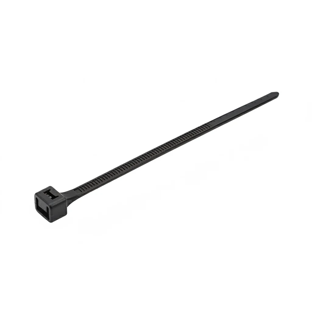
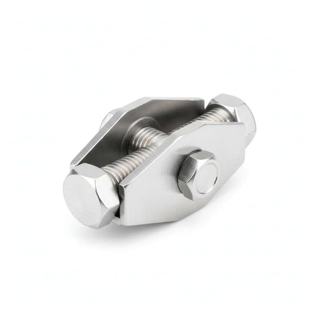
| Nylon Cable Tie (Heat-Resistant) | Cable Clamp | Cable Tray Snap Clip | Cable Protection Sleeve | |
|---|---|---|---|---|
| SPEC | 4.8×300mm / 7.6×500mm | For 10-50mm cables | For cable trays | Nylon corrugated tube φ15-30mm |
| MATERIAL | PA66+Heat Stabilizer | 304 Stainless Steel | 304 Stainless Steel | PA6 Flame Retardant |
| GRADE | UL 94 V-2 Black | A2-70 | A2-70 | UL 94 V-0 |
| FINISH | HDG >=55um per ISO 1461 | HDG >=55um per ISO 1461 | HDG >=55um per ISO 1461 | HDG >=55um per ISO 1461 |
| CORROSION | C3 (ISO 12944-2) | C3 (ISO 12944-2) | C3 (ISO 12944-2) | C3 (ISO 12944-2) |
| TEMP | -20°C to +80°C | -20°C to +80°C | -20°C to +80°C | -20°C to +80°C |
| WEIGHT | ~0.5 kg/piece | ~0.5 kg/piece | ~0.5 kg/piece | ~0.5 kg/piece |
| MOQ | 100 pcs | 100 pcs | 100 pcs | 100 pcs |
| PACK | VCI paper + carton | VCI paper + carton | VCI paper + carton | VCI paper + carton |
| STD | ISO 898-1, GB/T 3098.1 | ISO 898-1, GB/T 3098.1 | ISO 898-1, GB/T 3098.1 | ISO 898-1, GB/T 3098.1 |
| USE | Cable bundling and fixing in tower middle and bottom sections | Cable fixing in high-temperature tower top section | Grouping and fixing cables inside cable trays | Additional protection for cables at bends |
PROCEDURE
- Route cables along the tower wall, grouping power and control cables separately per the separation rules in IEC 60364-5-52.
- Place the PA66 heat-stabilized nylon tie around the cable bundle and pull snug, leaving a small gap to avoid crushing the insulation.
- For the tower-top high-temperature zone, mount the 304 stainless steel cable clamp with the EPDM liner over the cable, then tighten the screw to a firm but not overtightened feel.
- Space vertical fixings every 2-3m; at bends, reduce spacing to ≤1m and insert the PA6 flame-retardant corrugated sleeve over the cable before clamping.
- Secure cables within the tray using the 304 snap clip at intervals of 1.5-2m for horizontal runs, pressing the clip until it locks.
- Verify each clamp holds the cable without slippage under a gentle tug and that no sharp edges contact the sheath.
COMMON ERRORS
| ✕ WRONG | CONSEQUENCE | ✓ CORRECT |
|---|---|---|
| Using ordinary nylon ties in the top high-temperature section (above 60°C) | Ties become brittle within 2 years and break, releasing cables that then whip against the tower wall during sway, damaging insulation. | Use 304 stainless steel clamps or ties in the upper 1/3 of the tower where temperatures reach 60-70°C. |
| Fixing cables only at top and bottom, leaving the 80m free section unsupported | Full self-weight (200-500kg) pulls on top terminals, deforming them, raising contact resistance, and causing overheating and ground faults. | Install intermediate clamps every 2-3m vertically to distribute the cable weight segmentally to the tower structure. |
| Clamping cables at a bend without increasing fixing density or using a guide plate | Excessive bending stress and sway cause insulation cracking from the inner side of the bend, and sharp tray edges can cut the sheath. | Increase fixing density to ≤1m at bends, install curved guide plates (R≥100mm), and chamfer all metal edges (R≥2mm). |
MAINTENANCE
Inspect cable ties and clamps seasonally and after any major storm; check for brittleness, cracking, or loosening, especially in the top tower section where temperatures exceed 60°C. Replace any tie showing signs of embrittlement or breakage, and re-torque stainless clamps if loose. Verify that bend-radius fixings remain ≤1m apart and that guide plates show no wear.
Plan B · Enhanced Configuration for Coastal/Large Turbines
C4 Harsh per ISO 12944-2
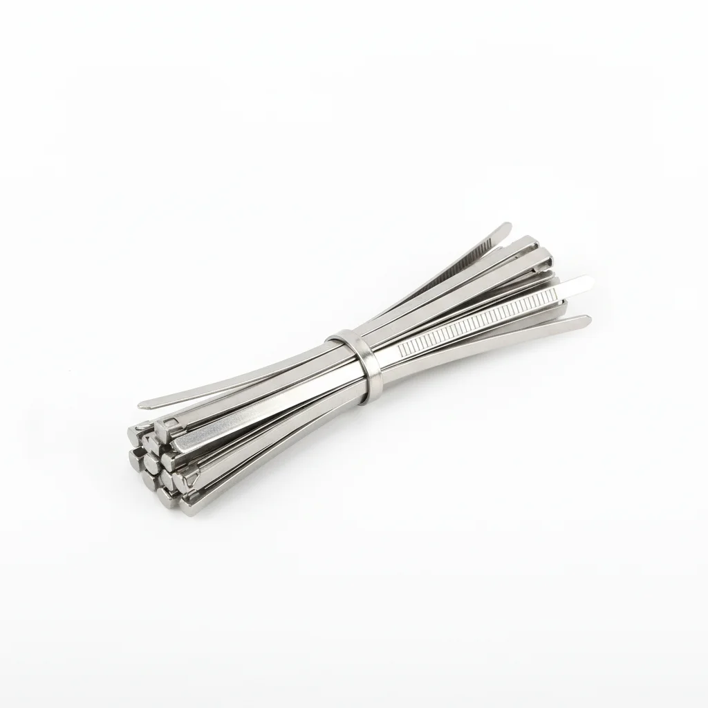
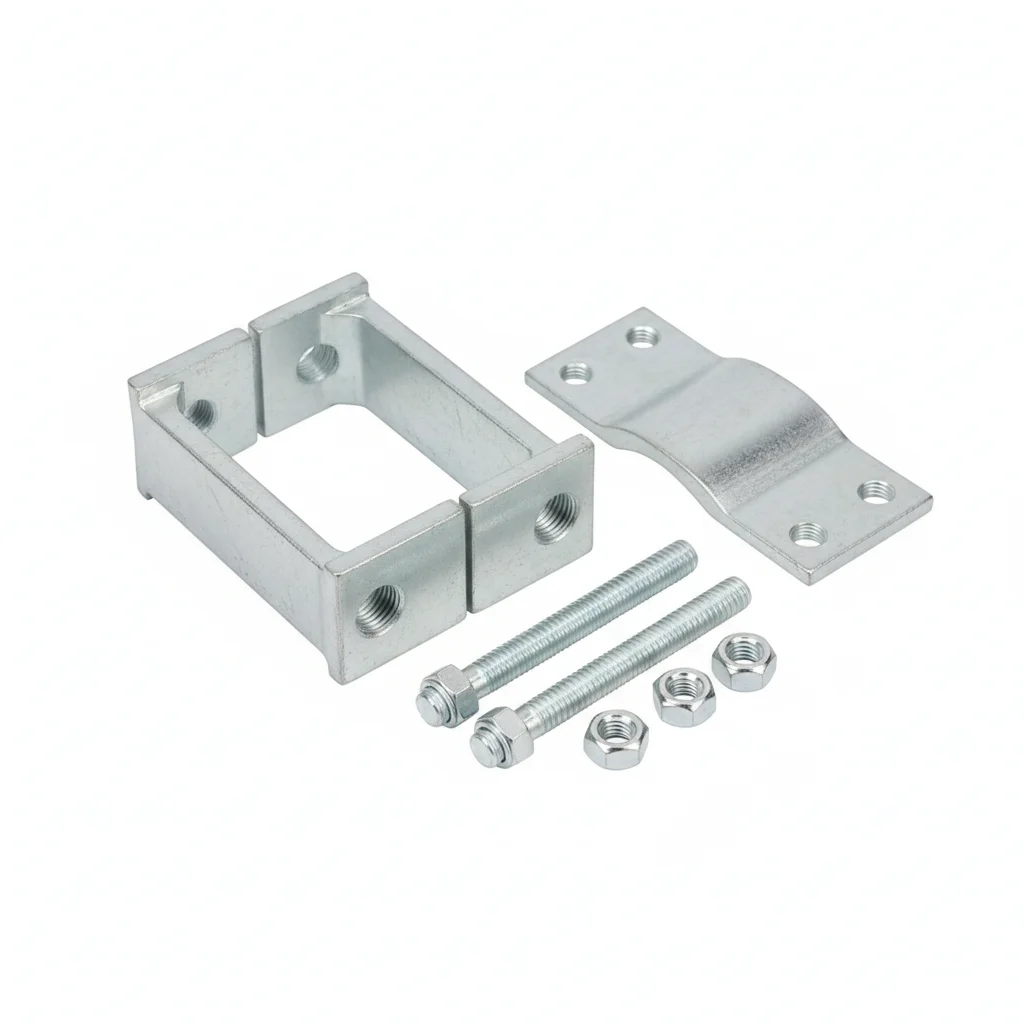
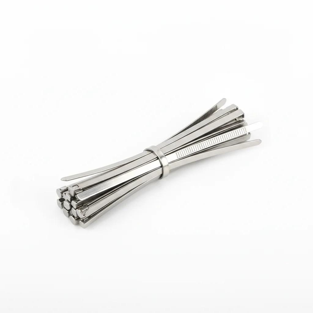
| Cable Tie | Cable Clamp (Reinforced) | Curved Cable Tray Guide Plate | Cable Tension Sensor | |
|---|---|---|---|---|
| SPEC | 4.6×300mm | For 20-80mm cables | R≥100mm | / |
| MATERIAL | 316 Stainless Steel | 316 Stainless Steel | 316 Stainless Steel | / |
| GRADE | A4-70 | A4-70 | A4-70 | / |
| FINISH | HDG >=55um per ISO 1461 | HDG >=55um per ISO 1461 | HDG >=55um per ISO 1461 | HDG >=55um per ISO 1461 |
| CORROSION | C3 (ISO 12944-2) | C3 (ISO 12944-2) | C3 (ISO 12944-2) | C3 (ISO 12944-2) |
| TEMP | -20°C to +80°C | -20°C to +80°C | -20°C to +80°C | -20°C to +80°C |
| WEIGHT | ~0.5 kg/piece | ~0.5 kg/piece | ~0.5 kg/piece | ~0.5 kg/piece |
| MOQ | 100 pcs | 100 pcs | 100 pcs | 100 pcs |
| PACK | VCI paper + carton | VCI paper + carton | VCI paper + carton | VCI paper + carton |
| STD | ISO 898-1, GB/T 3098.1 | ISO 898-1, GB/T 3098.1 | ISO 898-1, GB/T 3098.1 | ISO 898-1, GB/T 3098.1 |
| USE | All-tower stainless steel fixing solution | Power cable fixing for large turbines | Cable guidance and protection at bends | Recommended for large turbines to monitor cable tension |
PROCEDURE
- At each bend, mount the R≥100mm curved guide plate so its profile matches the cable's required bend radius, then fasten it with 316 stainless steel clamps.
- Secure vertical cable runs with 316 stainless steel cable ties at 2–3m intervals; reduce spacing to ≤1m at platform transitions.
- For power cables 20–80mm, use the reinforced cable clamp with A4-70 hardware and verify the clamp's grip does not deform the sheath.
- If a cable tension sensor is included, install it at the lowest fixing point to monitor cumulative load from the cable weight above.
- After all clamps are set, tug each cable by hand to confirm no slippage and that the bend follows the guide plate without sharp edges.
- Log the torque applied to each clamp nut and the environmental conditions at installation for future reference.
COMMON ERRORS
| ✕ WRONG | CONSEQUENCE | ✓ CORRECT |
|---|---|---|
| Using 304 stainless steel ties in a coastal environment | Chloride pitting initiates on 304 within a few seasons, weakening the tie and releasing the cable during tower sway. | Select 316 stainless steel ties (A4-70) for all coastal and large-turbine installations. |
| Mounting the curved guide plate with sharp edges facing the cable | Tower sway rubs the cable against the un-chamfered edge, cutting the sheath and causing insulation failure. | Inspect the guide plate for chamfered edges (R≥2mm) and orient it so the smooth side contacts the cable. |
| Tightening the reinforced clamp without a torque wrench | Over-tightening crushes the cable insulation, increasing contact resistance and heat; under-tightening lets the cable slip and stress terminals. | Use a calibrated torque wrench and follow the clamp manufacturer's specified torque range. |
MAINTENANCE
Seasonally inspect all clamps for signs of corrosion, especially at welds and edges; replace any with pitting deeper than 0.3mm. At each overhaul window, verify that cable ties remain taut and re-tension any that have loosened due to thermal cycling. Check guide plates for wear and confirm the bend radius is still ≥10 times the cable diameter for power cables.
Plan C · Highest Grade for Offshore Wind Farms
C5-M Extreme per ISO 12944-2
| Cable Tie | Cable Fixing Clamp | Firestop Partition Cable Transit Seal | |
|---|---|---|---|
| SPEC | 4.6×300mm | For 30-100mm | Custom |
| MATERIAL | 316L | 316L Stainless Steel | EPDM Rubber |
| GRADE | A4-80 Electro-polished | A4-80 | Flame Retardant V0 IP68 |
| FINISH | HDG >=55um per ISO 1461 | HDG >=55um per ISO 1461 | HDG >=55um per ISO 1461 |
| CORROSION | C3 (ISO 12944-2) | C3 (ISO 12944-2) | Not applicable (polymer) |
| TEMP | -20°C to +80°C | -20°C to +80°C | -20°C to +80°C |
| WEIGHT | ~0.5 kg/piece | ~0.5 kg/piece | ~0.5 kg/piece |
| MOQ | 100 pcs | 100 pcs | 100 pcs |
| PACK | VCI paper + carton | VCI paper + carton | VCI paper + carton |
| STD | ISO 898-1, GB/T 3098.1 | ISO 898-1, GB/T 3098.1 | ISO 898-1, GB/T 3098.1 |
| USE | All-tower cable fixing on offshore platforms | Large cross-section power cables for offshore turbines | Firestop sealing for platform cable penetration holes |
PROCEDURE
- Before fixing, clean the cable surface and the tower attachment points with a marine-grade solvent to remove any salt residue.
- Position the 316L cable tie around the cable bundle, ensuring the EPDM lining (if present) fully covers the cable contact area.
- For power cables 30–100mm, use the cable fixing clamp with A4-80 hardware, torquing the bolts evenly to avoid point loading.
- At platform cable penetration holes, install the firestop partition transit seal, compressing the EPDM module around each cable to achieve an IP68-rated seal.
- Secure vertical runs every 2–3m, but at bend sections reduce spacing to ≤1m and use a curved guide plate with R≥100mm to maintain the required bend radius.
- After installation, perform a continuity check on all cable clamps to ensure no metal part is in direct contact with the conductor.
COMMON ERRORS
| ✕ WRONG | CONSEQUENCE | ✓ CORRECT |
|---|---|---|
| Using standard 316 clamps instead of 316L in the offshore splash zone | The higher carbon content of 316 promotes sensitization and accelerates corrosion in chloride-rich environments, leading to premature clamp failure. | Specify 316L (A4-80) for all offshore cable fixing hardware. |
| Skipping the firestop seal at cable penetration holes | Without the seal, fire and hot gases can spread between tower compartments, and moisture ingress corrodes the clamps and cables. | Always install a firestop partition transit seal with flame-retardant EPDM (V0 rated) and verify its IP68 rating. |
| Over-tightening A4-80 bolts beyond the specified torque | Excessive torque can strip threads or crack the clamp body, especially in cold temperatures, leading to loss of clamping force. | Follow the torque specification for A4-80 hardware and use a calibrated wrench; re-check after the first thermal cycle. |
MAINTENANCE
At each scheduled offshore maintenance visit, inspect all 316L clamps for crevice corrosion, especially under EPDM pads and at weld seams. Replace any component showing pitting or rust staining. Verify the firestop seals remain intact and watertight. Annually, torque-check a 10% sample of clamps to ensure they have not loosened due to vibration.
SUPPLIER CAPABILITY
Quality, Delivery & Customization
Quality Control
- ✓MTC material certificates with every batch
- ✓Key parts sampled for hardness/salt spray/torque coefficient
- ✓100% inspection or AQL sampling before shipment
Delivery
- ✓Standard parts made to order: 7-15 days
- ✓Custom parts: 25-45 days
- ✓FOB/CIF/DDP supported
Customization
- ✓Drawing review and material matching
- ✓Non-standard sizes/heads/threads
- ✓Small-batch prototyping supported
Certification
- ✓Material certificates (MTC)
- ✓Spectrographic analysis reports
- ✓Salt spray test reports (on request)
MOQ: No MOQ for standard parts; custom parts assessed by process complexity
FAQ
FAQ
RELATED READING
Keep Reading & Next Step
BEYOND TECHNICAL SPECS
Finding the right factory, controlling quality, delivering on time — that's the real challenge. We cover fasteners, rubber, plastics, industrial textiles. One team, end to end.
SEE CAPABILITIES →